HAL Id: hal-02430903
https://hal.telecom-paris.fr/hal-02430903
Submitted on 7 Jan 2020
HAL is a multi-disciplinary open access
archive for the deposit and dissemination of
sci-entific research documents, whether they are
pub-lished or not. The documents may come from
teaching and research institutions in France or
abroad, or from public or private research centers.
L’archive ouverte pluridisciplinaire HAL, est
destinée au dépôt et à la diffusion de documents
scientifiques de niveau recherche, publiés ou non,
émanant des établissements d’enseignement et de
recherche français ou étrangers, des laboratoires
publics ou privés.
A Model-Based Combination Language for Scheduling
Verification
Hui Zhao, Ludovic Apvrille, Frédéric Mallet
To cite this version:
Hui Zhao, Ludovic Apvrille, Frédéric Mallet. A Model-Based Combination Language for Scheduling
Verification. Model-Driven Engineering and Software Development, Springer International Publishing,
2020. �hal-02430903�
A Model-Based Combination Language for Scheduling
Verification
?
Hui Zhao1, Ludovic Apvrille3, and Fr´ed´eric Mallet12
1 Universit´e Cˆote d’Azur, I3S, INRIA 2 I3S Laboratory, UMR 7271 CNRS, France 3 LTCI, T´elecom Paris, Institut Polytechnique de Paris
Abstract. Cyber-Physical Systems (CPSs) are built upon discrete software and hardware components, as well as continuous physical components. Such hetero-geneous systems involve numerous domains with competencies and expertise that go far beyond traditional software engineering: systems engineering. In this pa-per, we explore a model-based approach for systems engineering that advocates the composition of several heterogeneous artifacts (called views) into a sound and consistent system model. A model combination Language is proposed for this purpose. Thus, rather than trying to build the universal language able to capture all possible aspects of systems, the proposed language proposes to relate small subsets of languages in order to offer specific analysis capabilities while keep-ing a global consistency between all joined models. We demonstrate the interest of our approach through an industrial process based on Capella, which provides (among others) a large support for functional analysis from requirements to com-ponents deployment. Even though Capella is already quite expressive, it lacks support for schedulability analysis. AADL is also a language dedicated to system analysis. If it is backed with advanced schedulability tools, it lacks support for functional analysis. Thus, instead of proposing ways to add missing aspects in either Capella or AADL, we rather extract a relevant subset of both languages to build a view adequate for conducting schedulability analysis of Capella func-tional models. Finally, our combination language is generic enough to extract pertinent subsets of languages and combine them to build views for different ex-perts. It also helps maintaining a global consistency between different modeling views.
Keywords: CPS, MDE, Combination Modeling Language, SysML, AADL, Multi-View Design
1
Introduction
CPSs (Cyber-Physical Systems) consists of various components and their intercon-nections [15]. Thus, the design of the CPSs span over numerous domains of the sys-tem. Handling requirements of different domains with different characteristics pushes model-based approaches to their limits.
?This work was financially Supported by the CLARITY project and by a UCN@Sophia Labex
Model-Driven Engineering (MDE) is considered as a well-established software de-velopment approach that uses abstraction to bridge the gap between the problem space and the software implementation [7][23]. MDE uses models to describe complex sys-tems at multiple levels of abstraction. In this paradigm, models are first-class elements that represent abstractions of a real system, capturing some of its essential properties. Models are instances of modeling languages which define their abstract syntax (e.g., using a metamodel expressed in a class diagram), concrete syntax (e.g., graphical or textual), and semantics (e.g., operational or denotational by means of a model transfor-mation) [12]. As an important issue of MDE, multi-view modeling integrates different models using various DSMLs (domain-specific modeling languages) and abstract vari-ous aspects of systems and sub-systems, such as scheduling, behaviors and functional-ities. Therefore, it is critical to understand the relationship among (meta) models. The modeling languages, such as Systems Modeling Language (SysML) [10] and Architec-ture Analysis and Design Language (AADL) [8], have been enhanced to better handle the CPS design, but, to the best of our knowledge, none of them cover all the necessary domains to handle all the characteristics of CPSs effectively. The increasing complexity of CPSs brings a critical challenge for developers to deal with different domains. De-velopers have to rely on domain-specific languages to handle different domains, which results in a proliferation of languages and increasing design complexity of CPS [9, 15]. Furthermore, the gaps between languages and platforms bring several problems, for example, the specification of the CPS that has problems with inconsistency and inco-herency. All of those problems are exposed at integration and simulation stages, they also augment the complexity of CPS and make it skyrocketing.
To tackle these problems, a new approach is required to efficiently take advantage of each existing language and combine them together. To this end, the existing approaches can be classified into two types. The first type is to continuously integrate the necessary languages into an existing development platform, and then progressively build a com-prehensive development platform. However, this type of approach could encounter a never-ending process and result in a gigantic framework, thus difficult to use, maintain, etc. The second type is to keep each language (or tool) isolated, and relate some of the elements from each language with (sub) meta-model, so as to allow different kinds of analysis offered by each method (e.g., scheduling analysis, safety analysis). Further-more, each domain expert can work independently with the second type of approach. However, since each language has its own characteristic, such as syntax and seman-tics, the gaps between different languages have to be eliminated in order to handle the consistency issues.
Our previous work [27] introduced a formal approach to combine two modeling languages by defining how to link two (sub-)metamodels. More precisely, thanks to our approach, consider two models m1and m2of two different modeling languages: m2can
automatically be augmented with some information of m1so as to perform verification
on the enriched model (e.g., scheduling, timing, safety), and then verification results can be backtraced to m1.
In order to validate our contribution, SysML and AADL are selected as two target languages, and their support environments (tools) Capella/Arcadia and OSATE2 4are
used to show the design of example system.
The paper is organized as follows. In section 2, we first identify the workflow of the proposed approach. Then, we explicitly present the reinforced language and the operators in section 3. In section 4, we apply these operators on functional and physical views. To evaluate the proposed formal approach, train traction control systems are used to demonstrate the architecture and analyze scheduling in section 5. Section 6 illustrate the related work. Finally, section 7 concludes the paper and presents our future work. It should be noted that, in sections 2, 3, 4 and 5, all elements on the left of transformation rules belong to metamodels of Arcadia, and all elements on the right are from the AADL metamodels. These metamodels have been imported by default, and their prefix (e.g., MM.Arcadia.function) are omitted for conciseness.
2
Our Approach
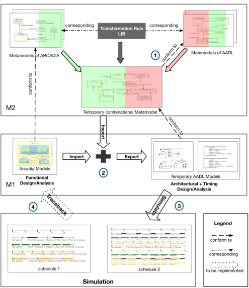
In this section, we describe the workflow we propose using an example based on Arca-dia and AADL, as shown in figure 1 [27]. ArcaArca-dia is well adapted to describe how to allocate functions, while AADL focuses on the concrete execution behaviors of com-ponents. In this paper, we use transformation to enhance Arcadia with the scheduling analysis features of AADL. The transformation is performed by proposing a set of rules and operators to specify the relationships at the M2 level. Those relations are used for model transformation purpose and a set of all relationships is called Transformation Rule Library (TRL). More specifically, these rules are used to establish a relationship between Arcadia and AADL metamodels in a Transformation Rule Library. We assume that Arcadia and AADL define concepts that can be put in relation thanks to the pro-posed rules.
As shown with the green part in the figure 1, an Arcadia function allocated to a pro-cessor can be related to a ”thread” in AADL. Additional attributes in Arcadia must be added (e.g., period and execution time) when one feature has no equivalence, as shown with a red part in figure 1). Then, the elements of metamodels are chosen manually depending on the requirements of the project. Finally, the workflow has four steps. In step one, we can get a temporary combinational metamodel (TCM) at run time by us-ing TRL once the equivalence relations between the two metamodels have been settled. In step two, the TCM can be used to combine an AADL model with elements of an Arcadia model, then the new AADL model can be exported into OSATE for further editing. In step three, the Cheddar analysis tool [22] is used to conduct scheduling sim-ulation. This tool can be used to detect designing flaws, time and resources conflicts. In step four, it traces back the results to the Arcadia model in order to help the designer enhancing the performance of his/her model.
Import Transformation Rule LIB Import Arcadia Models Functional Design/Analysis M2 M1
Temporary AADL Models Architectural + Timing Design/Analysis Simulation schedule 1 schedule 2 Simulate Traceback 1 2 3 4 conform to corresponding corresponding Legend conform to Export corresponding to be implemented conform to Metamodels of AADL Metamodels of ARCADIA
Temporary combinational Metamodel conform to
Fig. 1. Overview of Workflow
3
Model Combination Language
The proposed Language is a dedicated (meta) language to extend and enrich one DSML’s capability by combining the other DSMLs. With this language, an integration engineer can explicitly capture combination scenarios at the language level. Combination pattern is used to specify different combination relationships. Specific operators are provided to build up Transformation Rule Expression (TRE), a set of TRE defines a TRL (Trans-formation Rule Library) which specifies how to combine different (meta) models’ ele-ments. Once the TRL is completed, it can be parsed by an automatic tool. Afterwards, the tool can perform the transformation automatically. The concept of combination lan-guage is illustrated in figure 2.
TRL (Transformation Rule Library) Operators + Elements TRE TRE TRE (Transformation Rule Expression) Patterns Specification Parsed by Realise Tool
Fig. 2. Concept of Combination Language
3.1 Specification
A specification consists of combination patterns and corresponding TRL. It defines what and how elements from different models are combined. Once it is specified, inte-gration experts can share this specification thus allowing the reuse and tuning of TRL. As a specification can explicitly describe combination relationship, it also can be used to decompose models by bi-directional techniques for some decomposition needs.
3.2 Combination patterns
Currently, We predefine a number of essential combination patterns, which provide all the declarations used in all the following examples. However, thanks to our language, designers can build other combination patterns depending on their problems and re-quirements. Certainly, they have to define some new combination patterns in the form of TRL.
1. Association: The association pattern is the most common phenomenon and easier to understand. It is used to indicates one element associate to another element and their related sub-elements (for example, its embedded element or associated attributes). 2. Removal: The removal pattern indicates the situation, where some element does
not be needed for new models according to requirements.
3. Correspondence The Correspondence pattern indicates building an equivalence re-lationship among a set of elements.
4. Notation: The notation pattern aims to hint people to add some extra information which is not existing in model. For example, the dependency relationship among the model’s elements, and the nature of the elements.
3.3 Abstract syntax of Combination Language
We give an abstract syntax of Combination Language by using a metamodel expressed in a class diagram (shown in figure 3). The major element of Combination Language is a specification that contains Patterns, Operators and TRL. The specification requires importing at least two (meta) models. The imported (meta) models serve as a source of a set of candidate elements for following operations. An operator selects the elements and their attributes from imported (meta) models, and it also specifies how to combine selected elements with a clear relationship.
Each operator contains a Transformation Rule Expression which relies on a strict definition by EBNF (Extended BackusNaur Form). Symbols are used to construct the TRE. For instance, for adding security properties to a logical component of Capella, it has to specify the corresponding element and their related attributes in TTool by using TRE. Specification [1..n] patterns Pattern Transformation Rule Express Transformation Rule Library Operators [2] (meta) models Element (meta) Model Attribute [1..n] attributes [1..n] TREs [1..n] Operators [1..n] Elements [1] TRL Symbol [1..n] Symbols [1..n] Elements
3.4 Meta symbol and notations rule expression
In this subsection, we firstly introduce some notations and meta symbols which are fun-damental elements for constructing the well-defined Transformation Rule Expressions (see table 1). For the propose to obtain strict definition and non-ambiguous Transfor-mation Rule Expression pattern, we use EBNF to define TRE. EBNF is a notation tech-nique for context-free grammars5, often used to describe the syntax of languages [17].
Symbol Meaning Γ Transformation Rule ; End of rule : Separate elements Transfer <> Parent node { } Attribute [ ] Optional value | Alternative + Object to be created ¬ Ignorer @ Notation
Table 1. Symbols of transformation rule expression
The detail literal meaning of symbols are as below:
1. A Transformation Rule Expression begins with ”Γ” and ends with ”;”. 2. The symbol ” ” indicates a transfer action.
3. A transfer action contains the source elements which in the left side of ” ” and the target elements in the right side. A simple example is as bellow:
Γ < parent > source target; 4. Symbol ”:” separates each part of TRE.
5. An angle brackets ”<>” encloses the parent node if the element has one or more parent nodes.
6. A parentheses ”{ }” enclose attributes
7. A square braces ”[ ]” delimit optional elements.
8. The alternative value is separated by a pipe ”|”. For example, The port has a direc-tional attribute called Direction which could be in or out shown as:
Port: {Direction[in|out]}
9. Symbol ”@” indicates the notations which are used to add some extra informations such as dependency and nature. The extra informations are handled as the same as operational value: enclosed in [ ]; separated by ”,”. For example, Port@[ModelA, Security]
means element Port belongs to ModelA and is used for Security purpose (view). In such situation, it makes tools automatically display or hide the element Portwhich
is in modelA and for security view in the following process.
With those symbols, we can build up plentiful TREs. Some more detailed examples of Transformation Rule Expressions are shown in the listing 1.1.
3.5 Abstract syntax of rule expression in EBNF
As we mentioned in the previous subsection, the TRE consists of one or more sequences of symbols. We list here the context-free syntax in EBNF in this subsection.
hexpressioni ::= Γ htermi htermi;|hexpressioni:htermi; |hoperatori htermi; htermi ::= helementi | hoperatorihelementi |hoperatorihelementihoperatori hoperatori ::= ’@’ | ’+’ | ’¬’ |’ ’
helementi ::= helementi|hattributei |hoptional valuei
3.6 Operators and semantics
The context-sensitive syntax and the operational rules could also be considered to be semantics instead of syntax. For example, the context-sensitive syntax is called static semantics in the UML specification documents from OMG [18]. In our case, it specifies how an instance of a construct can be meaningfully connected to other instances.
In order to make the TRE more clearly and precisely, we firstly present a set of relationships definitions formally. That is used to help users understand the semantics of the operator and to avoid ambiguity and misunderstanding. Secondly, we propose a set of operators to build up Transformation Rule Expression, which represents operations between (meta) models (e.g., transforming, creating, ignoring) in a systematic way. They may also help users to understand the following TRE examples.
We define a relation in the sense of set theory. Let A and B be a set of elements respectively, with a, b, c and x, y, z: elements of model, this is written as A ) a, b, c and B ) x, y, z.
– Relationship: If the ordered pair (a, x) in our relation, we write
R
(a, x) or aR
xfor simplicity. It is also a boolean function.R
(a, x) is true means existing a relation between a and x.– Equivalence:
E
(a, x) is a boolean function that is true if and only if a semantically equals to x. By functionE
(a, x) holdsR
(a, x) ∧E
(a, x).– NotIn: ¬a is a boolean function. If it is true, that means there are any corresponding elements in set of B (x, y, z) which either have a relationship with a, nor semantically equal to a. Formally,
Operators:
(a) Transferring operator: We use indicates transferring operator, for example, a xit means that transfer from a to x, if and only if
E
(a, x) is true, in other words, a and x is Equivalence relationship.(b) Creating operator: In the case of creating a new attribute, put the name of an at-tribute in the parentheses with plus ”{ }+”, that is used to present the option which is to be created. For example, Γa x : {y}+;, it means that transfer from a to x and add y attribute, if and only if y ⊃ x and
E
(a, x) ∧R
(a, y) ∧R
(x, y) is true. An example in practice is below,ΓPort Port : {Type[data|event|dataevent]}+
A port will be transferred to another port element, and to create new attribute named Typethat associates to port with three optional value (data, event, data and event). (c) Ignoring operator: This operator is used for some ignored attributes and objects.
It is denoted with symbol ”¬” which is in front of the object. For example, ¬a, it means a is NotIn object of set B. Formally, ¬
R
(a, B) ∨ ¬E
(a, B).(d) Notation Operator:This operator is used for tagging the nature of attribute of an el-ement. There is an example: Port@[ModelA, Security]. It can present two attributes
of element Portwith two tags. One is ModelA, indicating that the element Port
be-longs to ModelA. In other words, It represents a dependency relationship between this element Port and element ModelA. Another is Security, represents an element
Port for Security purpose. It would be used to catalog the elements for displaying
or fast selecting purpose.
TRE examples with semantics: Transformation Rule Express (TRE) represents the transforming relationships. It would be used for guiding the integration engineer or for reading by automated transformation engine. We use some more detailed examples of Transformation Rule Expressions to explicitly explain how it works. Please refer to the TRE table which is in the listing 1.1.
In line 1 of this example, we firstly transfer an element port (it has direction at-tribute) of A to an object element port of B, and add a new attribute Type with three optional value (date, event or data event). These ”type value” can be recognised by model B’s DSML and the supported environment. The added attribute can be used to continue further design as well. In line 2, it is similar to previous one, but the object element Port has a parent node called feature which is enclosed in a pair angle brackets. Secondly, in line 3, it shows an ignored element, in which the source element may not be found a corresponding one in the object model, or the source element is not needed by the object model. Finally, in line 4, it is a Equivalence relationship between the source element and the object element, in other words, it’s a set of one by one trans-formations which transfer ”Exf un” to ”connection”, ”Source” to ”source” and ”Target”
to ”target”, respectively.
1ΓPort:{Direction[in|out]} <feature>:Port:{Direction[in|out]}:{Type[data|event|data event
]}+;
3ΓPort:¬{ordering};
4ΓExf un:{Source}:{Target} <connections>:connection:{source}:{target};
Listing 1.1. The example of transformation Rule Expressions
4
Transformation Rule Library
As we described in the above section, the Transformation Rule Express play an im-portant role in the transformation process. Hence, in this section, we will show how to construct a set of TREs called the Transformation Rule Library (TRL). We also re-spectively present the following views, functional view and physical view in Arcadia (SysML) and AADL. Each view contains one or more metamodels which represents as a x-tuples.
4.1 Functional view
Logical components in Arcadia The logical components in Arcadia contain a set of member elements, such as logical component containers, functions, ports, and func-tional exchanges. In the Arcadia, Funcfunc-tional diagrams consist of a set of SysML blocks and its interactions, named Logical components; The notion of Logical components en-ables better expression of system engineering semantics compared to SysML, and par-ticularly, reduces the bias towards software. SysML block definition diagrams (BDDs) and internal block diagrams (IBDs) are assigned to different abstract and refined layers, respectively. The definition of a block in SysML can be further detailed by specifying its parts; ports, specifying its interaction points; and connectors, specifying the connec-tions among its parts and ports. This information can also be visualized using logical components in Arcadia. In the definition 1, we present a metamodel of an instance of logical components.
Definition 1. (Logical Component) A logical component (LC) is 5 tuples,
LC
=< Comp, Fun, Port, Exf un, Mc f> where, Comp= ∞∑
i=1 Funiis a logical component container which contains a set of functional elements.
Fun is a finite set of functional block include their name and id attributes. Port is
a finite set of functional ports including directions and allocation attributes. Exf un⊆
Port× Port denotes a finite set of functional exchange (connection) between two
func-tional ports, it must be pair, one is source, another is target. Mc f: ΣFun→ Compallocate
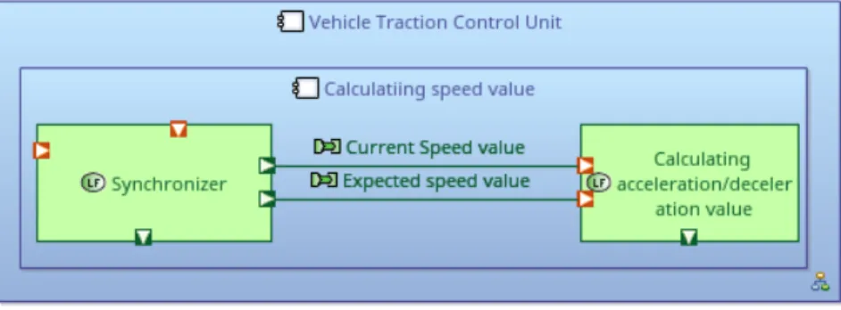
Fig. 4. An example of functional view of vehicle traction control unit in ARCADIA
In the figure 4, there is a functional instance model of a part of a vehicle traction control unit in ARCADIA as an example. The blue rectangle is named logical com-ponent in Arcadia, but we consider it as a function’s container, we thus call it logical component container Comp in this paper. The green rectangle are functions Funwhich
are contained by Comp. The element Mc fhas represented this allocation relationship
be-tween logical component containers and functions Mc f : ΣFun→ Comp. The deep green
square with the white triangle is the outgoing port (Port), which connects to an
incom-ing port (Port) that is drawn as a red square with white triangle and the green line is the
functional exchange between two functional ports (Exf un).
The metamodels of software in AADL AADL is able to model a real-time system as a hierarchy of software components, predefined software component types in the category of the components such as thread, thread group, process, data, and subprogram are used to model the software architecture of the system.
Definition 2. (Software Composition) A SC is a 4-tuples:
SC
=< Type, Port,Connection, Annex >where Type specifies the type of components (e.g, system, process, thread). Port is a set of communication point of component. Port could be different types such as data port, event port and data event port. And, port can specify the direction such as in port, out port, in out port. Connection is used to connect ports in the direction of data/control flow in uni- or bi-directional. Annex is defined for the refinement of component, in this paper, we used hybrid annex to explicitly describe the both discrete and continuous behavoir of train traction control system.
Hybrid Annex We use the HA to declare both discrete and continuous variables in the Variables section, and the initial values of constants are given in constant section.
Assert is used to declaring predicates which may be used with invariants to define a condition of operation. The behavior section is used to specify the continuous behavior of the annotated AADL component in terms of concurrently executing processes, and use continuous evolution — a differential expression to specify the behavior of a phys-ical controlled variable of a hybrid system. The communication between computing units and physical components are an essential part of a hybrid system, Communica-tion between physical processes uses the channels declared in the channel secCommunica-tion, and communicate with an AADL component relies on ports that are declared in the compo-nent’s type. Continuous process evolution may be terminated after a specific time or on a communication event. There are invoked through timed and communication interrupt, respectively. A timed interrupt preempts continuous evolution after a given amount of time. A communication interrupt preempts continuous evolution whenever communi-cation takes places along any one of the named ports or channels. The definition 3 gives a metamodel of Hybrid Annex which does not exist in SysML-based environment. Definition 3. (Hybrid Annex)
A Hybrid Annex is a 8-tuples:
H A
=< Ass, Ivar,Varhd,Conshd, Proc,ChP, Itr, Bitr>where Ass is a finite set of assert for declaring predicates applicable to the intended con-tinuous behavior of the annotated AADL component. Ivar is associated with assert to define a condition of operation that must be true during the lifetime. Varhdis a finite set
of discrete and continuous variables. Conshdis a finite set of constants which must be
initiated at declaration. Procis a finite set of processes that are used to specify continuous
behaviors of AADL components. ChP is a finite set of channels and ports for synchro-nizing processes. Itr is a finite set of time or communication interrupts. Bitr: Itr → Proc
binds interrupts to related processes.
Functional elements transformation rules The table 2 shows the correspondence be-tween AADL and Arcade elements. The Additional attributes column are the attributes to be created during the transformation. According to this table, we can easily write the transformation rules to transforming Arcadia to AADL on functional parts, denoted
LC
SC
+H A
. An example as below (listing 1.2 [27]):1ΓComp Type[ system|process]:{Runtime Protection[true|false]}+;
2ΓFun Type[abstract|thread]:{Dispatch Protocol[Periodic|Aperiodic|Sporadic|Background|
Timed|Hybrid]}+;
3 ...
Listing 1.2. Functional elements transformation rules example
4.2 Physical view
Execution Platform in AADL Processor, memory, device, and bus components are the execution platform components for modeling the hardware part of the system. Ports and
Ar cadia AADL Additional attrib utes Notation Logical component container (C om p ) System,Process { Runtime Protection[true |f alse] } + @[function |AADL |scheduling] Function (Fun ) Abstract, Thread { Dispatch Protocol[Periodic |Aperiodic |Sporadic |Background | T imed |Hybrid] } + @[function |AADL |scheduling] Port (Por t ) Port { T ype[data |e v ent |data ev ent] } + @[function |AADL |scheduling] Functional Exchange (E xfun ) Connection ∅ ∅ Anne x { T ype[abstract | thread] } :{ anne x } + @[function |AADL |scheduling] Ph ysical Node (N od e ) De vice,Memory ,Processor ,Bus { Dispatch Protocol } +: { Period } :{ Deadline } +: { priority } + @[ph ysic |AADL |scheduling] Ph ysical Port (PP ) ∅ ¬ PP @[ph ysic |AADL |scheduling] Ph ysical Link (PL ) Bus/BusAccess { Allo wed Connnection T ype } +: { Allo wed Message Size } +: { Allo wed Ph ysical Access } +: { T ransmission T ime } + @[ph ysic |AADL |scheduling] T able 2. Functional and Ph ysical elements correspondence table
port connections are provided to model the exchange of data and event among compo-nents. Functional and non-functional properties like scheduling protocol and execution time of the thread can be specified in components and their interactions.
Definition 4. (Execution Platform)
A EP component is defined as a 3-tuples:
EP
=< EC, BA,Conn>where,EC defines the execution component such as processor, memory, bus and device.
BAdefines the BusAccess which is interactive approach between bus component and
other execution platform components. Conn⊆ EC ×EC denotes a finite set of connection
between two components via bus device.
Physical components in Arcadia The physical component in Arcadia consists of phys-ical Node, Port and Link. The Physphys-ical Port and Link correspond to port and bus con-nection in AADL. There are some choices when the physical Node is translated to AADL such as device, memory, and processor, hence the designer has to point out what type of target component during transformation by using transformation rule express. Definition 5. (Physical Components)
A Physical components is 3-tuples,
P C
=< Node, PP, PL >where, Nodeis a execution platform, named node in Arcadia, it could be different type
of physical component (e.g, processor, board). PP is the physical component port. PL is physical link, it could be assigned a concrete type such as bus.
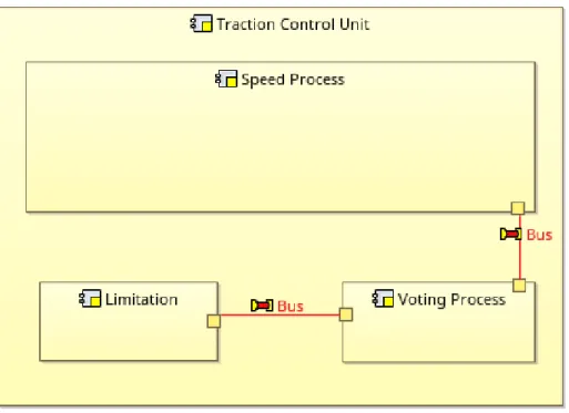
Figure 5 is shown as a part of physical instance model of vehicle traction control unit in ARCADIA. We can see the yellow parts are the physical node (Node) and the
red line is the physical link (PL) named bus in this case which connects to two physical ports (PP), the small square in dark yellow.
Physical elements transformation rules According to the table 2, we can easily write the transformation rules for physical elements. Listing 1.3 [27] shown as a part of the code to transform the physical component from Arcadia to AADL.
1ΓNode [Device|Process|Memory|Bus]:{Dispatch Protocol}+:{Period}:{Deadline}+:{
priority}+;
2ΓPP ¬PP;
3ΓPL Bus/BusAccess:[{Allowed Connnection Type}+:{Allowed Message Size}+|{ Allowed Physical Access}+:{Transmission Time}+];
Fig. 5. An example of physical view of vehicle traction control unit in ARCADIA
What we have to especially explain is the physical link part (see line 3). The Bus device could be a logical resource or hardware component. Hence, the bus device has different properties depending on the role. When the bus is considered as a logical re-source, it contains the properties Allowed connection type and Allowed Message Size. When the bus is hardware, it contains Allowed Physical Access and Transmission Time. Therefore, we write the rules that either
{Allowed Connnection Type}+ : {Allowed Message Size}+ or
{Allowed Physical Access}+ : {Transmission Time}+
5
Case Study
To show the efficacy of our approach in transforming and using produced AADL models to analyze the properties, this section presents the experimental results of analyzing the traction controlling unit of railway signaling system. By using our proposed approach, we transfer and extend Arcadia metamodel, and design AADL using OSATE2 with the generated metamodel. once the concrete models have been created, the scheduling property is chosen to show analysis ability through Cheddar tool [22].
Fig. 6. Arcadia model of TCU system
5.1 Train Traction Control System
Train movement is the calculation of the speed and distance profiles when a train is traveling from one point to another according to the limitations imposed by the signal-ing system and traction equipment characteristics. As the train has to follow the track, the movement is also under the constraints of track geometry, and speed restrictions and the calculation becomes position-dependent. The subsystem of calculating the trac-tion effective and speed restrictrac-tions is therefore critical to achieving train safe running. Nowadays, Communication Based Train Control (CBTC) system is the main method of rail transit (both urban and high-speed train) which adopts wireless local area net-works as the bidirectional train-ground communication [28]. To increase the capacity of rail transit lines, many information-based and digital components have been applied for networking, automation and system inter-connection, including general communi-cation technologies, sensor networks, and safety-critical embedded control system. A large number of subsystems consisting of modern signaling systems of railways, there-fore, system integration is one of the key technologies of signaling systems; it plays a significant role in maintaining the safety of the signaling system [26].
This paper uses a subsystem which called Traction Control Unit system (TCU) from signaling system of high-speed railway. We use this TCU system to illustrate the model transformation from engineering level to detailed architectural level and verified the instance models. The functional modules such as calculation and synchronization will be transformed using our approach, and then non-functional properties such as timing correctness and resource correctness will be verified by schedule analysis tool Ched-dar [22].
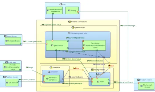
First, we start with component functional views and physical view analysis by de-signing system models in Arcadia (shown in figure of TCU 6 [27]). The functions of
Traction Control Unit Alarm Tractional coefficient GeoMaps GPS value Setting value Maps Position HMI Locomotive Operation Display GPS BaliseSensor 20ms 30ms Voter Voter Acc/Dec value status sync msg coefficient Restriction Restricted condition c_mrin c_prin c_rout status c_cv c_sv c_rv calculating speed value
Calculating Acc/Dec Synchronizer sync c_cc c_scc c_cs Expected speed c_sec c_cs Current speed 60ms Acc/Dec value 40ms
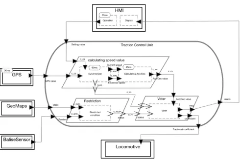
Fig. 7. AADL model of TCU system
the traction control system are to collect the external data by sensors such as a speed sensor. The data from Balise sensors is used to determinate the track block, and then it is going to seek the speed restriction conditions by matching accurate positioning (if the track blocks are divided fine enough) and digital geometric maps data. Meanwhile, calculating speed unit received the speed data from GPS and speed control commands from HMI (Human-Machine Interface) periodically. GPS data provides speed value pe-riodically (we set a period of 30 seconds in this case), and HMI data sustainedly send the operation command with the period of 20 seconds till the value changed (e.g., ex-pected speed value), then the calculating unit has to output an acceleration value and export to the locomotive mechanical system. Although they are periodic, the external data do not always arrive on time due to transmission delay or jitter. Therefore, we should use a synchronizer to make sure they are synchronized. Otherwise, the result would be wrong with asynchronous data. Similarly, to ensure the correctness of the command of acceleration (or deceleration), we applied a voting mechanism which can ensure the result is correct as much as possible. The voter must have the synchronized signal and restriction condition to dedicate to output the acceleration coefficient request to the locomotive system. The AADL diagram is shown in figure 7 [27].
5.2 Model transformation
Using the Arcadia2AADL tool, the metamodel of the TCU system in Capella is trans-lated into the corresponding AADL metamodel with the rules and approach which de-scribes in section 4. For instance, on the one hand, the function class is translated into the thread in AADL. To analyze the timing properties, several attributes also have been added such as protocol type, deadline, execution time, period.
On the other hand, the physical part element Node translates to the processor in this case. Differ from simple physical Node in Arcadia; the processor element attaches rich properties such as scheduling protocol (scheduler type), process execution time. The allocation relationships on both physical and functional parts are translated into AADL as well.
5.3 Schedule verification
The external data and internal process work sequentially is an essential safety require-ment of the system, and each task should be scheduled properly. However, in real-world, the risk of communication quality and rationality of scheduling must be taken into ac-count. Therefore, the schedule verification is a way to evaluate system timing property. An Ada framework called Cheddar which provides tools to check if a real-time applica-tion meets its temporal constraints. The framework is based on the real-time scheduling theory and is mostly written for educational purposes [16].
1 thread implementation synchronizer . impl
2 properties
3 Dispatch Protocol => perodic;
4 Period => 100 ms;
5 Deadline => 100 ms;
6 Compute Execution Time => 50..60ms;
7end synchronizer . impl;
8
9 thread implementation calalculating . impl
10 properties
11 Dispatch Protocol => perodic;
12 Period => 100 ms;
13 Deadline => 100 ms;
14 Compute Execution Time => 30ms..40ms;
15end calalculating . impl;
16
17 thread implementation gps. position
18 properties
19 Dispatch Protocol => perodic;
20 Period => 40 ms;
21 Deadline => 40 ms;
22 Compute Execution Time => 30ms..40ms;
23end gps. position ;
24
25 thread implementation HMI.setting
26 properties
27 Dispatch Protocol => perodic;
28 Period => 30 ms;
29 Deadline => 30 ms;
30 Compute Execution Time => 20ms..30ms;
31end HMI.setting ;
Listing 1.4 shows a set of 4 periodic tasks (cal, pos, sync and setting) of TCU respectively, defined by the periods 100, 100, 40 and 30, the capacities 60, 40, 30 and 20, and the deadlines 100, 100, 40 and 30. These tasks are scheduled with a preemptive Rate Monotonic scheduler (the task with the lowest period is the task with the highest priority).
For a given task set, if a scheduling simulation displayed XML results in the Ched-dar. One can find the concurrency cases or idle periods (see left of figure 8, comprise the software part and physical device part). People change the parameters directly and reload simulation; a feasible solution can be applied instead. After tuning, finally, the appropriate setting has displayed as in right of figure 8. According to this simulation result, people can correct the properties value in AADL, thereby ensure the correctness of system behavior timing properties.
(a) Schedule 1 with idel time (b) Schedule 2 with compact time
Fig. 8. Simulation results of tasks schedule
6
Related work
We have presented our approach to extending SysML-based engineering framework Capella to AADL and analyzed the relationships among Arcadia and AADL models in different view at the metamodel level. Likewise, a considerable number of studies have been proposed on ”language extension, modeling languages integration and composable language components”. This section provides a brief introduction to these works.
The complexity of the development of CPS has been the significant problems which puzzle the developers. It is not only from the nature of problems but also from the de-velop languages. Elaasar et al. has discussed [6] about the limit of UML which exacer-bate the complexity of development, and proposed an approach to reduce the complex-ity of UML tools by implementing and adapting the ISO 42010 standard on architecture description.
Efficient integration of different heterogeneous modeling languages is essential. Modeling language integration is onerous and requires in-depth conceptual and tech-nical knowledge and effort. Traditional modeling language integration approaches
re-quire language engineers to compose monolithic language aggregates for a specific task or project. Adapting these aggregates to different contexts requires vast effort and makes these hardly reusable. Arne Haber et al [11] presented a method for the engineering of grammar-based language components that can be independently developed, are syntac-tically composable, and ultimately reusable.
In despite of existing a lot of studies on the combining SysML and AADL [4] or on the extending SysML with AADL [2]. Differ from the above studies, our approach dedicates to smoothly combine engineering platform Capella/Arcadia, AADL and its annex, and our approach can be easily applied to other languages through fine-tuning. In practice, one could design global system at a high level and then seamlessly refine the models within AADL and its annex for further analysis such as scheduling. In other words, our approach can properly extend Arcadia’s design and analysis capabilities to AADL, while essentially keeping its independence.
An approach for translating UML/MARTE detailed design into AADL design has proposed by Brun et al. [3]. Their work focuses on the transformation of the thread execution and communication semantics and does not cover the transformation of the embedded system component, such as device parts. Similarly, in [25], Turki et al. pro-posed a methodology for mapping MARTE model elements to AADL component. They focus on the issues related to modeling architecture, and the syntactic differences be-tween AADL and MARTE are well handled by the transformation rules provided by ATL tool, yet they did not consider issues related to the mapping of MARTE proper-ties to AADL property. In [19], Ouni et al. presented an approach for transformation of Capella to AADL models target to cover the various levels of abstraction, they take into account the system behavior and the hardware/software mapping. However, the formal definition and rigorous syntactic of transformation rules are missed.
Behjati et al. describe how they combined SysML and AADL in [2] and provided a standard modeling language (in the form of the ExSAM profile) for specifying em-bedded systems at different abstraction levels. De Saqui-Sannes et al. [4] presented an MBE with TTool and AADL at the software level and demonstrated with the flight management system. Both of their works do not provide the description in a formal way.
In industrial domain applications, Suri et al [24] proposed a model-based approach for complex systems development by separating the behavior model and execution logic of the system. Moreover, they used UML based languages to model system behavior and connected the behavior models to external physical API of CPS. It focuses on providing a solution for the modularity and interoperability issues related to Industry 4.0 from a systems integration viewpoint.
S. Apel et al [1] also studied on different model driven methods for heterogenic systems for Electric vehicle. They have tried to evaluate how model-driven engineering (MDE) combined with generative frameworks can support the transfer from platform independent models to deployable solutions within the logistical domain.
The work of Kurtev [14] is used in the x-ray machine, it provided a family of domain-specific languages that integrate existing techniques from formal behavioral and time modeling. F. Scippacercola [21] have explored the application of model-driven engineering on the interlocking system (a subsystem of signaling system of the
rail-way). They discussed how to reduce efforts and costs for development, verification, and validation in a critical system.
The modeling language scientists have proposed some specific methods to weave the models as well as metamodels formally such as [13], Degueule has proposed Melange, a language dedicated to merging languages [5], and similar works like [20]. However, the structural properties are not supported.
Compared with current studies, the approach proposed in this paper has the follow-ing features:
1. A proper subset of AADL has been chosen as the transformation target including functional software composition, execution platform. We use it to describe contin-uous behaviors of Cyber-Physical System.
2. All of the transformations is considered at metamodel level, and then a synthesized metamodel can be used to create concrete AADL models for further analysis. 3. Transformation rules are formally defined, and then it is readable by human and
easier to verify the correctness of transformation.
7
Conclusions and future work
In this paper, we proposed a language-based design approach for combining different modeling design artifact (called views). At the beginning of this paper, we explicitly introduce the workflow of the proposed approach. Then we give the definition of syntax and semantics of our language. We selected system engineering methodology Arcadia (based on SysML) and architectural design language AADL as a vehicle for demonstrat-ing the effectiveness of our approach and of model combination language for scheduldemonstrat-ing verification. We did so for two reasons. Firstly, the integrating of heterogeneous compo-nents and elaborate model integrity concept in system design are challenging problems while using numerous model language to describe different views of one system (or subsystem). Since our proposed language is generic enough to extract pertinent subsets of languages, if it works well for combining Arcadia and AADL, it should also work for the others, less demanding major modifications and extra cost of learning. Secondly, Enriching the functional design with scheduling ability can discover the conflicts in the early stage and improve the performance of CPSs in practice in a better way. Hence, Our language is competent for combining the composition of several heterogeneous artifacts (views) into a sound and consistent system model.
Especially, we give a formal description of the key modeling elements of Arcadia and AADL, respectively. Then we give some example of transformation rules which guide transforming from these Arcadia metamodels to AADL formally. Finally, a case study of train traction controlling system is used to demonstrate the transformation from engineering concerned design into an architectural refinement design which can be further analyzed by scheduling properties to find flaws of functional design.
Although our proposed language-based approach is effective and has been proven by many instances in practice, there are some drawbacks to use our approach: i) people have to spend times to learn the syntax of rules, and the writing of rule is error-prone. ii) the traceback function is not yet implemented automatically.
In our future work, we will try to build a graphic interface to write rules, and the writing errors of the rule can be detected. We also have to implement the traceback of simulation results, which is sketched in our workflow with the arrow in dotted line. The results must be used automatically by upstream modeling framework. To this end, we have to extract the critical information from cheddar outputting file and transform to an appended file of modeling tool which can be recognized by the tool and hint user in somehow. Secondly, we will study the transformation rules for more elements of Arcadia and also for comprehensive SysML elements, even for other UML-like profiles such as MARTE. At the same time, we will continue to explore the AADL and its annex to support more analysis and formal verification of system design. Besides, the safety-critical systems have become a trend in industrial files. We will study the extension of AADL with verification of safety properties with transformation methodology.
References
1. Apel, S., Mauch, M., Schau, V.: Model-driven engineering tool comparison for architec-tures within heterogenic systems for electric vehicle. In: 2016 4th International Conference on Model-Driven Engineering and Software Development (MODELSWARD). pp. 671–676 (Feb 2016)
2. Behjati, R., Yue, T., Nejati, S., Briand, L., Selic, B.: Extending SysML with AADL concepts for comprehensive system architecture modeling. In: European Conference on Modelling Foundations and Applications. pp. 236–252. Springer (2011)
3. Brun, M., Vergnaud, T., Faugere, M., Delatour, J.: From UML to AADL: an Explicit Execu-tion Semantics Modelling with MARTE. In: ERTS 2008 (2008)
4. De Saqui-Sannes, P., Hugues, J.: Combining SysML and AADL for the design, validation and implementation of critical systems. In: ERTS2 2012 (2012)
5. Degueule, T., Combemale, B., Blouin, A., Barais, O., Jezequel, J.M.: Melange: A meta-language for modular and reusable development of dsls. In: Conf on Software Language Engineering. pp. 25–36. ACM (2015)
6. Elaasar, M., Noyrit, F., Badreddin, O., G´erard, S.: Reducing uml modeling tool complexity with architectural contexts and viewpoints. In: MODELSWARD. pp. 129–138 (2018) 7. Ergin, H., Syriani, E., Gray, J.: Design pattern oriented development of model
transforma-tions. Computer Languages, Systems & Structures 46, 106–139 (Nov 2016)
8. Feiler, P.H., Gluch, D.P.: Model-based engineering with AADL: an introduction to the SAE architecture analysis & design language. Addison-Wesley (2012)
9. Garlan, D.: Modeling challenges for cps systems. In: 2015 IEEE/ACM 1st International Workshop on Software Engineering for Smart Cyber-Physical Systems. pp. 1–1 (May 2015). https://doi.org/10.1109/SEsCPS.2015.8
10. Group, O.M.: OMG Systems Modeling Language (May 2017)
11. Haber, A., Look, M., Perez, A.N., Nazari, P.M.S., Rumpe, B., Vlkel, S., Wortmann, A.: Inte-gration of heterogeneous modeling languages via extensible and composable language com-ponents. In: 2015 3rd International Conference on Model-Driven Engineering and Software Development (MODELSWARD). pp. 19–31 (Feb 2015)
12. Harel, D., Rumpe, B.: Modeling Languages: Syntax, Semantics and All That Stuff, Part I: The Basic Stuff (Aug 2000)
13. Jezequel, J.M.: Model driven design and aspect weaving. Software and Systems Modeling 7(2), 209–218 (2008)
14. Kurtev, I., Schuts, M., Hooman, J., Swagerman, D.J.: Integrating interface modeling and analysis in an industrial setting. In: MODELSWARD. pp. 345–352 (2017)
15. Lee, E.A.: Cyber Physical Systems: Design Challenges. In: 2008 11th IEEE International Symposium on Object and Component-Oriented Real-Time Distributed Computing. pp. 363–369. IEEE (2008)
16. Marc´e, L., Singhoff, F., Legrand, J., Nana, L.: Scheduling and Memory Requirements Anal-ysis with AADL. In: SIGAda. pp. 1–10. ACM (2005)
17. McCracken, D.D., Reilly, E.D.: Backus-naur form (bnf) (2003) 18. OMG: OMG Unified Modeling Language (Apr 2015)
19. Ouni, B., Gaufillet, P., Jenn, E., Hugues, J.: Model Driven Engineering with Capella and AADL (2016)
20. Ramos, R., Barais, O., Jezequel, J.M.: Matching model-snippets. In: Conf on Model Driven Engineering Languages and Systems. pp. 121–135. Springer (2007)
21. Scippacercola, F., Pietrantuono, R., Russo, S., Zentai, A.: Model-driven engineering of a railway interlocking system. In: 2015 3rd International Conference on Model-Driven Engi-neering and Software Development (MODELSWARD). pp. 509–519 (Feb 2015)
22. Singhoff, F., Legrand, J., Nana, L., Marc´e, L.: Cheddar - a flexible real time scheduling framework. SIGAda pp. 1–8 (2004)
23. Stahl, T., Voelter, M., Czarnecki, K.: Model-driven software development: technology, engi-neering, management. John Wiley Sons, Inc. (2006)
24. Suri, K., Cuccuru, A., Cadavid, J., G´erard, S., Gaaloul, W., Tata, S.: Model-based develop-ment of modular complex systems for accomplishing system integration for industry 4.0. In: MODELSWARD. pp. 487–495 (2017)
25. Turki, S., Senn, E., Blouin, D.: Mapping the MARTE UML profile to AADL. In: ACES-MB. pp. 11–20 (2010)
26. Wang, J., Wang, J.: A New Early Warning Method of Train Tracking Interval Based on CTC. IEEE Transactions on Intelligent Transportation Systems pp. 1–7
27. Zhao, H., Apvrille, L., Mallet, F.: Meta-models combination for reusing verification tech-niques. In: 7th International Conference on Model-Driven Engineering and Software Devel-opment. pp. 39–50. SCITEPRESS-Science and Technology Publications (2019)
28. Zhu, L., Zhang, Y., Ning, B., Jiang, H.: Train-ground communication in CBTC based on 802.11 b: Design and performance research. In: CMC’09. pp. 368–372. IEEE (2009)