HAL Id: hal-03133360
https://hal.archives-ouvertes.fr/hal-03133360
Submitted on 5 Feb 2021
HAL is a multi-disciplinary open access
archive for the deposit and dissemination of
sci-entific research documents, whether they are
pub-lished or not. The documents may come from
teaching and research institutions in France or
abroad, or from public or private research centers.
L’archive ouverte pluridisciplinaire HAL, est
destinée au dépôt et à la diffusion de documents
scientifiques de niveau recherche, publiés ou non,
émanant des établissements d’enseignement et de
recherche français ou étrangers, des laboratoires
publics ou privés.
VVUQ of a thermal-hydraulic multi-scale tool on
unprotected loss of flow accident in SFR reactor
Nathalie Marie, Simon Li, Amandine Marrel, Michel Marquès, Sophie Bajard,
Annick Tosello, Jorge Perez, Baptiste Grosjean, Antoine Gerschenfeld, Marine
Anderhuber, et al.
To cite this version:
Nathalie Marie, Simon Li, Amandine Marrel, Michel Marquès, Sophie Bajard, et al.. VVUQ of
a thermalhydraulic multiscale tool on unprotected loss of flow accident in SFR reactor. EPJ N
-Nuclear Sciences & Technologies, EDP Sciences, 2021, 7, pp.3. �10.1051/epjn/2021002�. �hal-03133360�
R
EGULARA
RTICLEVVUQ of a thermal-hydraulic multi-scale tool on unprotected loss
of
flow accident in SFR reactor
Nathalie Marie1,*, Simon Li1, Amandine Marrel1, Michel Marquès1, Sophie Bajard1, Annick Tosello1, Jorge Perez1, Baptiste Grosjean1, Antoine Gerschenfeld2, Marine Anderhuber2, Chotaire Geffray2, Yannick Gorsse2,
Gédéon Mauger2, and Laura Matteo2
1
CEA, DEN, DER, F-13108 Saint-Paul Lez Durance, France
2
CEA, DEN, DM2S, F-91191 Gif-sur-Yvette, France
Received: 6 April 2020 / Received infinal form: 24 November 2020 / Accepted: 5 January 2021
Abstract. Within the framework of the French 4th-generation Sodium-cooled Fast Reactor safety assessment, methodology on VVUQ (Verification, Validation, Uncertainty Quantification) is conducted to demonstrate that the CEA’s thermal-hydraulic Scientific Computation Tools (SCTs) are effective and operational for design and safety studies purposes on this type of reactor. This VVUQ-based qualification is a regulatory requirement from the French Nuclear Safety Authority (NSA). In this paper, the current practice of VVUQ approach application for a SFR accidental transient is described with regard to the NSA requirements. It constitutes thefirst practical, progressively improvable approach. As the SCT is qualified for a given version on a given scenario, the transient related to a total unprotected station blackout has been selected. As it is a very complex multi-scale transient, the SCT MATHYS (which is a coupling of the CATHARE2 tool at system scale, TrioMC tool at component scale and TrioCFD tool at local scale) is used. This paper presents the preliminary VVUQ application to the qualification of this tool on this selected transient. In addition, this work underlines some feedback on design and R&D aspects that should be addressed in the future to improve the SCT.
1 Introduction
In the framework of the French 4th-generation Sodium-cooled Fast Reactor (SFR), numerical simulations are performed to assess the design and the safety features of the nuclear facility. These simulations are realised with Scientific Calculation Tools (SCTs) that must be before-hand qualified according to the VVUQ (Verification, Validation, Uncertainty Quantification) approach. This VVUQ-based qualification is a regulatory requirement from the French Nuclear Safety Authority (NSA) formal-ized in the guide number 28 of NSA released in July 2017 [1]. This qualification guarantees the availability of effective and operational SCT for design and safety studies purposes. These tools enable to limit the conservatisms and thus to reduce the margins and sources of extra-costs (component design, prevention devices, etc…). The ulti-mate goal of VVUQ activities is to assist decision makers intaking aware decisions about an intended application.
While the NSA requirements are increasingly consid-ered to qualify scientific tools used in the safety
demonstration of Pressurized Water Reactors (PWR), the applications of the VVUQ methodology for some PWR transients, such as the Loss-Of-Coolant Accident (LOCA), have raised the difficulty of a strict application of these requirements. For example, EDF and Framatome have developed for this application a Best Estimate Plus Uncertainties (BEPU) methodology named CathSBI (Cathare Statistical Intermediate Break) which is designed to study Intermediate Break (IB) LOCA [2]. The CathSBI methodology, in addition to the consideration of multi-physics (fuel related) phenomena, includes some new features, notably the use of 3D thermal hydraulic modules of the CATHARE code. This is a first use in France in safety analyses and raised several issues [3]; indeed the methodologies usually involve only 0D-1D flow simula-tions. Moreover in this framework of PWR safety demonstration, a lot of work is still ongoing on simulation tool validation and quantification of TH code model input uncertainties. The validation is an on-going process taking advantage of the always new experimental facility results. The input uncertainty quantification (IUQ) on the physical models still requires further investigations, even if this issue has already been tackled in the past through three OECD/ NEA projects: Best-Estimate Methods Uncertainty and
* e-mail:nathalie.marie@cea.fr
© N. Marie et al., published byEDP Sciences, 2021
https://doi.org/10.1051/epjn/2021002 & Technologies
Available online at:
https://www.epj-n.org
This is an Open Access article distributed under the terms of the Creative Commons Attribution License (https://creativecommons.org/licenses/by/4.0), which permits unrestricted use, distribution, and reproduction in any medium, provided the original work is properly cited.
Sensitivity Evaluation (BEMUSE) [4], Post-BEMUSE Reflood Models Input Uncertainty Methods (PREMIUM) benchmark [5], Systematic APproach for Input Uncertain-ty quantification Methodology (SAPIUM). Indeed, the analysis of PREMIUM phases III and IV benchmark results has shown a large dispersion results between participants [6]. One main reason could be attributed to the lack of common consensus and practices in the followed IUQ process and method. Thus in France, even in the PWR safety demonstration, the establishment of the tool quantification (VVUQ) methodology, which should in addition be adapted to each safety transient, is not terminated.
There is not recent published VVUQ application on SFR transients in France. In fact, since the SuperPhénix reactor, the SFR safety demonstration has not been addressed in France. Furthermore, this demonstration should nowadays follow the regulatory requirements from the French NSA, which is a novelty compared to the SuperPhenix safety demonstration. In Japan, lots of studied have been carried out on the prototype SFR MONJU, the Japanese experimental SFR JOYO and finally the Japan Sodium-cooled Fast Reactor (JSFR). For the commercialization of SFRs in Japan, V&V procedures have been developed and, on some specific transients, statistical evaluations of the main safety variable (core hot spot temperature) have been performed [7]. Nonetheless, VVUQ method is not systematically followed for safety demonstration in Japan. Much effort has been devoted to the establishment of the“Safety Design Criteria (SDC)” for the Sodium-cooled Fast Reactor (SFR) system [8]. The objective of the SDC is to provide a set of general criteria for the safety designs of structures, systems and compo-nents of the Generation-IV Sodium-cooled Fast Reactors (Gen-IV SFRs), where the criteria are clarified systemati-cally and comprehensively, and are consistent with the GIF’s basic safety approach and with the aim of achieving the safety and reliability goals defined in the GIF Roadmap [9]. These SDC have been disseminated, updated and utilized for SFR designing worldwide. For these activities, harmonious interaction has already been started among research and design organizations of SFRs, regulatory bodies and their technical support organizations and international organizations such as IAEA and OECD/ NEA [10]. Among the TH issues related to SDC, there notably are the natural circulation decay heat removal and the highest temperature evaluation in a subassembly of the core [11]. Indeed, liquid sodium has high thermal conductivity and high boiling temperature at atmospheric pressure, allowing to consider in the safety approach the remove of decay heat by the natural circulation of the coolant as a passive safety system. As an SFR is operated under low pressure conditions, coolant leakage does not lead to the type of loss of coolant accident anticipated in a PWR involving depressurization, coolant boiling and the loss of cooling capability. Therefore, unlike a PWR, emergency core cooling systems for coolant injection under high and low pressure conditions are not necessary for an SFR. The only requirement for SFR core cooling is the retention of the sodium coolant level above the reactor core in the reactor vessel along with sufficient heat removal
capability and that the maximum clad temperature does not exceed the saturation temperature.
This paper addresses these issues related to SFRs Safety Design Criteria through the application of the VVUQ methodology for Scientific Computation Tool simulating a complex 3D TH transients in the French SFR prototype with regard to the French NSA require-ments. It constitutes the first practical, progressively improvable approach on VVUQ application on a SFR transient. As the SCT is qualified for a given version on a given scenario, 19 transients have been identified for SFR safety demonstration from a Phenomena identification and Ranking table evaluation (PIRT) [12]. Among them, the transient related to a total unprotected station blackout has been selected [13] (Sect. 2.2). This is a 2 h-time frame scenario which belongs to the Operating Situation of category 4 safety scale. Indeed this transient is one of the most 3D complex, involving thermal stratification in the upper and lower plena, natural circulation inside the main vessel and the primary loops. Moreover as the SDC is a local sub-assembly variable (the local maximum clad temperature), the simulation of this transient thus requires a multi-scale coupling of several thermal-hydraulic SCT to correctly capture the main 3D phenomena and the safety output results, taking into account all the associated uncertainties.
But as, it is not practicable to simulate the whole reactor in 3D, the SCT MATHYS (Multi-scale ASTRID Thermal-hydraulics) which features a coupling of CATHARE2 at system scale, TrioMC at component scale and TrioCFD at local scale is therefore required for this study.
After a slight description of the French SFR reactor in
Section 2, this paper will present the VVUQ application to the qualification of the MATHYS SCT on this unprotect-ed total station blackout transient inSection 3. It breaks down the steps of verification, validation (which confronts the domain of applicability/utilization to its domain of validation) and the quantification of various sources of uncertainties (boundary conditions, input, scenario, model…). In addition, this work presents the propagation and post-processing of a high number of parameters in
Section 4. These results also leads to afirst feedback on this reactor design. Some R&D aspects will also be addressed.
2 The SFR project
In the framework of the French SFR construction project, numerical simulations are performed to assess the design and safety of the reactor.
2.1 French SFR reactor
The studied French SFR reactor [14] is a pool type reactor composed of a main primary circuit, four sodium secondary loops and a power conversion system. It gathers some evolutions from the past reactors (Superphenix…) enabling to increase it safety level to the GEN IV reactors
requirements. Focusing on the core, the majors improve-ment is the CFV core (low sodium void effect core). This new core concept is an axial heterogeneous core of 1500 MWth on the contrary to more classical homogeneous cores used in former SFR. The low sodium void effect of the CFV core results mainly from the presence of a sodium plenum above thefissile zones combined to the presence of a fertile plate in the inner zone of the core encompassed by two fissile zones (displayed inFig. 1). The larger height of the
outer fissile zone enables the void reactivity effect to be lowered as well, due to neutron leakage enhancement [15]. Other innovative features of this reactor concern the core-catcher, the system of energy conversion, the inspectability of the in-core components, passive decay heat removal systems (Direct Heat Removal DHR). These systems, though responsible for major safety improvements, tends to induce new, hard-to-model physical phenomena. For instance, DHR systems at the top of a pool-type SFR tend to cool the core via several competing natural convection paths inside the core [16].
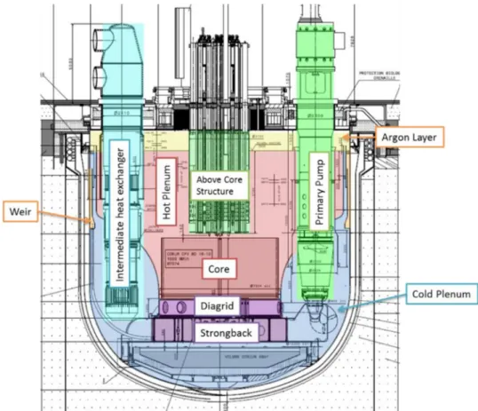
Figure 2 shows the schematic of this SFR primary circuit. The main vessel is around 18.5 m high and 16 m in diameter. It contains several passive and active decay heat removal systems. The nominal primaryflow rate is around 8500 kg/s from which 7900 kg/s goes through the core. The latter is composed of an inner core, an outer core, neutron-shielding and internal fuel storage [17,18]. Passive complementary safety devices such as hydraulically suspended absorber rod sub-assemblies (called RBH) are also part of the design [19].
2.2 Studied transient
The VVUQ process is applied to a calculation tool dedicated to the simulation of one reactor in one operating situation for design, safety analysis and operation. Itsfinal objective is to give the proof of the tool adequacy for this application with the quantification of the whole set of uncertainties. As the scientific tool is qualified for a given
Fig. 2. Schematic of the studied SFR primary circuit. Fig. 1. CFV general core geometry. On the left: radial cut at
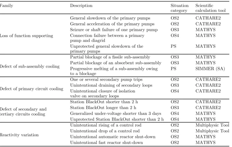
version on a given scenario, 19 transients have been identified for this SFR safety demonstration. These main types of transients are issued from many years of studies on SFR, especially on Phenix, Superphenix and EFR [20] and PIRTs on TH issues on SFR [12]. By the way, this has led to a development plans of multiphysics [21] or multiscale simulations [16] tools. The originality of this paper resides in the selection of 19 incidental or accidental transients, belonging to five families of transients (reactivity varia-tions, defect of primary circuit cooling, defect of sub-assembly cooling, defect of secondary and tertiary circuits cooling, loss of function supporting) and their associated classification in the situation categories given in a Framer’s diagram (composed of four types of Operating Situations (OS), Prevention Situations (PS), Mitigation Situations (MS) and Practically Eliminated Situations). This classi fi-cation aims at identifying the safety output variables for each transient. The adapted simulation tool for each simulation has been identified focusing on the main phenomena driving each transient and thus the required scales of resolution of TH in the various part of the reactor. These transients are reported inTable 1with the scientific tools required for their simulation and the associated safety output variables to the various situation categories are given inTable 2.
As the aim of this work is the demonstration of the feasibility of the VVUQ methodology and its first
application on SFR scope, only one transient among the 19 identified transients (Tab. 1), theUnprotected Station BlackOut shorter than 2 h (USBO) [13], has been selected for demonstration purpose of the practical applicability of this VVUQ methodology with regard to the NSA Table 1. 19 transients selected for this SFR safety demonstration (SA: Severe Accident).
Family Description Situation
category
Scientific calculation tool
Loss of function supporting
General slowdown of the primary pumps OS2 CATHARE2 General acceleration of the primary pumps OS2 CATHARE2 Seizure or shaft failure of one primary pump OS3 MATHYS Connection failure between a primary
pump and diagrid
OS4 MATHYS Unprotected general slowdown of the
primary pumps
PS MATHYS
Defect of sub-assembly cooling
Partial blockage of a fissile sub-assembly OS3 MATHYS Partial blockage of an absorbent sub-assembly OS3 MATHYS Progressive melting of a sub-assembly owing
to a blockage
PS SIMMER (SA)
Defect of primary circuit cooling
One or several secondary pump trips OS2 CATHARE2 Unintentional draining of secondary loops OS3 CATHARE2 Unintentional closure of isolation
valve on secondary loops
OS4 CATHARE2
Defect of secondary and tertiary circuits cooling
Station BlackOut shorter than 2 h OS2 CATHARE2 Station BlackOut longer than 2 h OS3 CATHARE2 Generalized under-voltage shorter than 3 days OS4 MATHYS Unprotected Station BlackOut shorter than 2 h OS4 MATHYS
Reactivity variation
Unintentional rising of a control rod OS2 Multiphysic Tool Unintentional drop of a control rod OS2 Multiphysic Tool Unintentional automatic reactor shut-down OS2 MATHYS Unintentional fast reactor shut-down OS2 MATHYS
Table 2. Decoupling criteria resulting from general safety criteria.
Category Decoupling criteria on cladding OS1 MCT< 700 °C
OS2 700°C < MCT < 750 °C less than 10’s 750°C < MCT < 800 °C less than 3’ MCT> 800 °C forbidden
OS3 Same as OS2 OS4 MNaT< T Sat
MCT< 800 °C PS MNaT< T Sat MCT< 825 °C
TMax hexagonal wrapper< 800 °C MS Mechanical Energy< [100 ;300] MJ
MCT, Maximum Clad Temperature; MNaT, Maximum Sodium Temperature.
requirements. This is a 2 h-timeframe scenario which belongs to an Operating Situation of Category 4 safety scale. Indeed this transient is one of the most complex single physic transient (thermal-hydraulic physics), in-volving thermal stratification in the plena and natural circulation inside the main vessel and the primary loops. It thus requires the multi-scale coupling of the MATHYS tool to correctly capture the main safety output results (the local maximum clad temperature and the sodium temper-ature at the outlet of the core Tab. 2).
During this USBO accident, the following events of this USBO accident are given inTable 3.
Att = 0 s, the scram signal is sent, the Primary Pumps (PP) trip and the shutdown of secondary (EMP) occur. The primary and secondaryflow rates decrease leading to the increase of the core temperature. As the primaryflow rate decreases, it reaches a design threshold (45% of nominalflow rate) which leads to the drop of the hydraulic prevention control rods (RBH). These rods are fully inserted in the core in 3 s. As they insert 722 pcm anti-reactivity per rod, after this 3 s delay only residual power needs to be removed. Other prevention control rods are designed on this reactor: the magnetic control rods (RBD) which fall when the sodium temperature at the outlet of the core exceeds 650°C. When the flow rate is low and sodium thermal stratification is established, natural circulation in the primary circuit then occurs due to buoyancy effects (sodium being heated in the core and cooled in the Intermediate Heat Exchangers (IHX)). Natural circulation in the secondary circuit increases the heat removal during thefirst 1000 s. After t = 1000 s, primary heat is no longer removed by the IHX. Residual power is nonetheless removed from the core thanks to the flow through the inter-wrapper (gap between hexagonal tubes surrounding the sub-assemblies). While theflow pattern changes in the Hot/Cold pools (large volumes above and below the core), the temperature slowly rises.
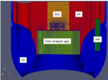
The Complete Computational Fluid Dynamics (CFD) domain nearly covers all the vessel (Fig. 3). Indeed, this transient involves 3D flow patterns in the pools, in the inter-wrapper gap and the primary side of the IHX. In addition, stratification of the sodium has a huge impact on the inlet temperatures of the PP and IHX, which, during
the transient, impact greatly the natural circulation (Fig. 4). This is why local simulation involving CFD calculations are requiredto properly account for these phenomena. Because of the high cost in time of CFD computations and the need to take into account external models such as neutronics (point kinetics in MATHYS) or PP performance maps, TH multi-scale and TH-neutronic multi-physics coupled solutions are applied to perform the calculations. In particular, the onset of natural circulation needs to be evaluated, along with sodium and cladding temperatures in the core (which are the outlet variables of interest). Furthermore, using multi-scale thermal-hydrau-lics coupled calculation tools enables to describe as precisely as possible the major structures (Above CoreStructure (ACS), Hot and Cold Plenum (HP and CP), sub-assembly and inter-wrapper gap for instance) and physical phenomena (buoyancy driven flow and inter-wrapper reversalflow for instance) while still maintaining a reasonable computing time effort. These computations involve advanced coupling methodologies. More details on this multi-scale model used for the coupled calculation can be found in [13]. The left side ofFigure 4 illustrates the primary circuit temperature field under nominal condi-tions, calculated by MATHYS whereas the right side shows the benefit of a multiscale TH simulation of this transient which enables to obtain the main phenomena identified by the PIRT [12].
– the pool stratification and heat transfer between poolswhich affect natural convection in the complete primary circuit;
– the inter-wrapper flow heat removal (and more generally of radial heat transfers in the core) and its effects on the hot pool thermal-hydraulics, as well as sodium recircula-tion in the core. The plena stratification is in turn influenced by the behavior of the sodium jets coming out of the core into the hot pool, and out of the IHXes into the cold pool: these jets are velocity-driven in forced convection, but turn upwards under the effect of buoyancy in natural convection.
Table 3. USBO events timeline. Time Events
t = 0 s
Trip of Primary Pumps (PP) Stop of secondary Electromagnetic Pump (EMP)
Power conversion system insulation (secondary to tertiary circuit thermal exchanges are considered to be null) t = 1000 s Secondary circuit insulation
(primary to secondary circuit thermal exchanges are observedto be null)
3 VVUQ application
In France, a professional guide was published in 2019 for PWR giving the main orientations to be followed by industrials (designers and operators of nuclear plants) to answer optimally to the recommendations of guide number 28 of NSA issued in July 2017 [1]. This guide states that, for a given transient, a SCT can be regarded as qualified when the VVUQ assessment (including scaling related uncer-tainties) has been properly completed. Concerning the qualification of a chaining or coupling of several tools (here, various thermal-hydraulic tools), the guide specifies that “there should not in principle be any difference in terms of qualification requirements by comparison with the case of a single tool”. Consequently a VVUQ processwas then achieved for the coupled multi-scale tool MATHYSversion v1.7.3. The qualification, which demonstrates the MATHYS adequacy for the realistic simulation of a USBO transient, has to provide the quantification of the whole set of uncertainties associated with the calculation of this situation or scenario.
Once the tool qualification is achieved, operators of nuclear plants could use this tool for safety demonstration. Based on these tool simulationsthey verify that the reactor is kept in a state which fulfilled the safety requirements (concerning the control of neutron reaction chain, decay heat removal and thus coolability of the reactor). For this purpose, it is necessary to demonstrate that the safety criteria representing the phenomenon of interest are verified with a certain margin. The safety margins provide an over-dimensioning which enables to overcome situations that would not be taken into account in the design. These safety criteria dictate the studied output variables (or Figures of merit) in the safety demonstration. These variables depend on the transient category. Here, for USBO accident which lies in the Operating Situation of category 4
on the safety scale, the criteria are the following (Tab. 2): – the temperature of the sodium should remain below the
saturation temperature;
– the maximum clad temperature should remain, taking into account the uncertainties, below 800°C.
These quantified decoupling criteria reflect a qualita-tive general safety criterion which stipulates that general clad fusion should not occur but some local fusion could be tolerated if their consequences remain limited.
The objective of this preliminary demonstration is to obtain the mentioned figures of merit and associated uncertainties for an USBO scenario by means of applying the MATHYS SCT; therefore, fulfilling each VVUQ step in the process.
3.1 Verification step
This step, which aims demonstrating that the equations are correctly solved from the numerical and data processing point of view, is accomplished for each tool (CATHARE2, TrioMC and TrioCFD) coupled inside MATHYS and is reported in the release notes of each tool and version specifying the used. This verification step is done as it is commonly the case. Equations in the simulations tools are checked:mass, energy and momentum are correctly solved and data transfer between components in the MATHYS tool are properly done. Moreover, as several situations are studied for the safety demonstration, the difficulty is to have a unique type of TH tool coupling for the simulation of each multiscale simulation. This was solved, at CEA, through the development of the unified “coupling tool”, called MATHYS, as a way to ensure that the same coupling algorithm is being applied in all cases. In this way, the verification step is reinforced. In MATHYS, the links and the interfaces between tools have also been verified. The coupled platforms developed in CEA (and MATHYS
Fig. 4. Nominal and natural convection states (subchannel calculation in the core, CFD calculation in the plena and inter-wrapper region) color is related to temperature scale as illustrative purpose;red-700K, blue-350K.
among them) solve the interface between codes using an API called ICoCo [22]. This code enables function calls for every coupled code such as information transmission, time step iteration or process.store/retrieve operations. The order in which the functions are called is based on the coupling methodology explained in details in [13]; TrioCFD and TrioMC are coupled using the domain decomposition method whereas the coupling between CATHARE2 and TrioCFD–TrioMC uses the domain overlapping method [13].
3.2 Validation step
This step commonly relies on the numerical validation by comparison with reference tools and/or analytical solu-tions, and on experimental validation by comparison with experimental data. More recently, efforts have been made to support these multi-scale approach with a comprehen-sive validation database relying, as for TH codes at various scale, on experiments at the separate-effects, combined-effect and integral scales. This experimental database consists of:
– Separate Effect Tests (SETs) dedicated to the study of each physical phenomenon relevant to the final reactor application in representative conditions;
– Integral Effect Tests (IETs), capable of reproducing interactions between these phenomena that may occur in thefinal reactor case;
– System and Integral Tests (SITs), or reactor-scale integral tests where all phenomena may come into play. This validation work is properly documented [13,23,24]. The complexity of this validation arises from considering the case of a coupling between three existing codes, such as a system/ sub-assembly/CFD codes coupling, where each of the codes usually benefits from an existing validation database. Counter-intuitively, this individual validation is not sufficient to validate the coupled tool itself, as the introduction of interactions between scales may lead to new physical phenomena, or new interactions, which are not covered by the codes’ individual validation matrices. For USBO transient, this interactions lead to, as already explained:
– pool stratification and heat transfer between pools on natural convection in the complete primary circuit; – inter-wrapper flow heat removal (and more generally of
radial heat transfers in the core) on hot pool thermal-hydraulics and on overall natural convection.
Constructing a validation matrix for the multi-scale tool then requires identifying separate-effects, integral effects and integral tests suitable for validating these phenomena and their interactions during the considered USBO transient.
However, it is important to underline that the experimental database for the validation of tools dedicated to SFR is far smaller than the one dedicated to PWR. Moreover, validating main TH phenomena at the system scale would require a high level of geometrical similarity, and thus adapted experiments for the studied new design. In contrast, the ability of CFD to simulate geometrical
effects directly makes it easier to argue that experiments performed for other designs (and thus in different geometrical configurations) will provide a useful contribu-tion for validating the new tool. Thanks to these arguments, multi-scale/CFD tool may thus rely on a growing experimental database for validating coupled effects:
– for the effect of pool thermal-hydraulics on natural convection, TALL-3D [25] (SET), CIRCE-HERO [26] (IET) and E-SCAPE [27] (IET) may be considered; – for the effect of inter-wrapper flow on S/A cooling,
THEADES [28] (SET), PLANDTL-1 [29] (IET) and PLANDTL-2 [30] (IET) are available or will be in the near future;
– CLEAR-S [31] (IET) will present an interesting case where it will be possible to validate the effect of pool TH and inter-wrapperflow on global natural convection at the same time;
– for integral validation, PHENIX [24], EBR-II [32] and FFTF [33] tests are or will be available in the short-term. These tests span two reactor types (loop for PLANDTL1/2 and FFTF, pool for all others) and two workingfluids (sodium or Lead-bismuth eutectic) as well as several design types: nevertheless, thanks to the geometri-cal genericity of multi-sgeometri-cale/CFD tools, they may all contribute to validating the application of the MATHYS tool on the studied USBO domain of utilization.
This domain of utilization of the MATHYS tool has been characterized by occurrence of main phenomena and expressed in ranges of pressure, coreflow rate (and thus velocity), temperatures and dimensionless numbers such as Reynolds number. These variables feature the reactor conditions along this transient. To define this scope using a selected influential parameters turns out to be a laborious exercise as the variables change with time. The domain of utilization can hardly be defined in detail, hence a macroscopic approach prevails. According to the VVUQ methodology, this domain of utilization should be compared to thedomain of validation of MATHYS, that is, the respective domains of validation of CATHARE2, TrioMC and TrioCFD corresponding to their domains of use in the reactor; for example the whole loop for CATHARE2, the two plenums, the ACS and the inter-wapper zone for TrioCFD, and the core sub-assemblies for TrioMC. Whereas the domains of validation of TrioMC and TrioCFD are quite well restricted, this is not the case for CATHARE2. As a result of the generalist nature of the CATHARE2 tool, experiments upon which are based its validation cover wide ranges of physical variables. The direct consequence is that the validation domain is also defined in a very macroscopic manner in the CATHARE2 validation reports. Furthermore, as it is difficult to cover, with the validation domain the domain of utilization, it might be somehow demonstrated (by sensitivity studies for example), that a lack in the validation domain might not have an influence on results of interest.
From this preliminary attempt to rigorously draw and compare the domain of utilization and the domain of validation on this complex USBO transient, it is concluded that the establishment of a precise methodology to achieve
this comparison is necessary; not to miss an important part of the validation domain. Moreover, at this stage, it is obvious that the domain of utilization for USBO cannot be encompassed within the domain of validation of MATHYS because some validation part of works are done on scaled experiments, possibly using simulatingfluids. Thus, even if the general phenomenon of interest is reproduced during this experiment, the ranges of influential variables do not correspond to the one of the domain of utilization. A transposition of this validation work should then be realized to the domain of utilization. By doing this, the domain of validation of the MATHYS tool becomes its domain of validity. This consists in the transposition or scaling step, sometimes added to the VVUQ. This step is dedicated to the extrapolation of the validation results to the intended scope of utilization considering the scale effect and the possible physical differences. Nowadays, and although some studies have been performed in this sense [34], the methodology to achieve this scaling or transposi-tion step is still fledgling and much belongs to R&D activities. It is commonly conceded that this step might lead to the quantification of particular uncertainties, linked to the move of the domain of validation to the domain of validity, called transposition uncertainties. In this present work, which consists on a preliminary application of the VVUQ methodology in SFR scope, these uncertainties have not been determined and less neither propagated. 3.3 Uncertainty quantification step
The uncertainties are of diverse natures: input or scenario uncertainties, design uncertainties, model uncertainties, numerical bias (temporal/spatial uncertainties), scaling/
transposition uncertainties. In this study, the uncertainties linked to the reactor design options are given in Table 4
from design reports with their associated probabilistic distributions. There are of course constraints which link the elements of the core geometry together in order to respect volume conservation. This will be taken into account through a constrained Monte Carlo experimental design (Sect. 4) Moreover, as the Best Practices Guidelines are meticulously followed for the 3 tools, the numerical bias are considered negligible. The scaling/ transposition uncer-tainties are not taken into account as discussed in the above section because the methodology to estimate them is not mature. The main scenario uncertainties have been selected through expert judgment of realistic transients, or bibliographic databases on past SFRs or sensitivity studies (seeTab. 5). Among them, we can notice the power level at the transient beginning, the main USBO transient feature;flow rate drop trigger value for the RBH rods is also important. The RBD rods are not considered in this list because, after several sensitivity studies, it happens that the sodium temperature at the top of the sub-assemblies never reaches the RBD triggering threshold during such transients.
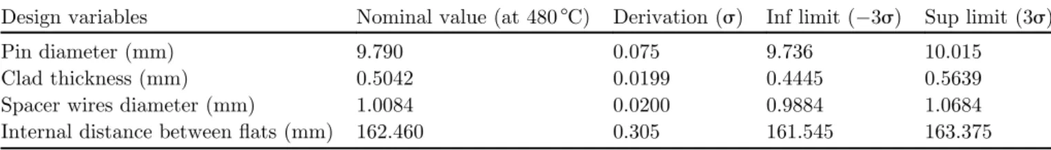
Thefinal work in this section aims at quantifying the influential uncertainties associated with the physical MATHYS tool models. As already explained, determining the input uncertainty quantification on the physical models still requires further investigations in PWR framework where a far larger amount of experimental data than for SFR is available. In PWR scope, these uncertainties are deduced from the validation step by the CIRCÉ (Inverse Quantification of Uncertainty) method [35] developed by CEA. This method has been extensively applied to the Table 4. Design uncertain variables linked to the core geometry– truncated normal law at ±3s⋅
Design variables Nominal value (at 480°C) Derivation (s) Inf limit ( 3s) Sup limit (3s) Pin diameter (mm) 9.790 0.075 9.736 10.015
Clad thickness (mm) 0.5042 0.0199 0.4445 0.5639 Spacer wires diameter (mm) 1.0084 0.0200 0.9884 1.0684 Internal distance betweenflats (mm) 162.460 0.305 161.545 163.375
Table 5. Main scenario uncertainties truncated normal law at ±3s⋅ Scenario variables Uncertainty
range at (±2s)
Nominal value Derivation (s)
Inf limit ( 3s)
Sup limit (+3s) Initial reactor power ±5% 1500 MW 2.5 7.5 7.5 Residual power ±20% Calculated decrease
(neutronic results)
10 30 30
Primary pumps inertia ±20% 8000 kg.m2 10 30 30 % of primaryflow rate; criterion
for RBH rods triggering
±20% 45% 10 30 30
Anti-reactivity of one RBH rod ±5% 722 pcm 2.5 7.5 7.5 Fall duration of RBH rods fall ±20% 3 s 10 30 30
physical models of the CATHARE 2 code. CIRCÉ is based on the principle of maximum likelihood (Frequentist category of methods), and quantifies basic parameters which fulfil two main assumptions: they follow a normal distribution law, and keep a linear relation with the tool responses. The basic parameters can be transformed logarithmically, so that CIRCÉ can also quantify parameters following a log-normal distribution. With the objective of obtaining the model uncertainties of CATHARE2, TrioMC and TrioCFD in their domains of utilization in sodium applications, the main influential models (characterized by sensitivity studies) of each tool have been listed with the associated separated effect tests which could help to their uncertainties determination. Unfortunately, it has appeared that the number of separated tests enabling to characterize a model is not important enough to apply the CIRCÉ method. Two ways have thus been followed:
– the procurement of these models uncertainties are taken from previous literature works or expert judgement. Usually, in this case, the uncertainties distribution is taken uniform to stay conservative. These obtained ranges of uncertainties are then propagated on the Best Estimate Plus Uncertainties (BEPU) simulations of dedicated experimental tests. If the results are within the range of experimental uncertainties, the chosen ranges of uncertainties are kept. Otherwise they are broadened and the propagation is repeated again until simulation results match the experimental results range.
– In parallel, a R&D advanced statistical work is pursued to quantify the validation and has for ultimate goal to determine the model uncertainties [36]. Indeed, general-ly, validation achievement constitutes a coarse valida-tion assessment, usually done, by roughly comparing each best-estimate simulation result with the experi-mental results. This research goes further in the
validation step by quantifying the agreement between the experimental and the simulation results taking into account the experimental uncertainties.
Thus, in this preliminary study, uncertainties on data of others physics are derived from sensitivity studies and uncertainty propagations with others SCT like ERANOS [37] (for the neutronics) and GERMINAL [38] for thermo mechanics.
Finally, the models uncertainties propagated through MATHYS in the USBO transient are reported inTables 6
and 7, with their associated probabilistic distributions. These lists have been restricted to the main influential model parameters determined beforehand from sensitivity studies and the uncertainties are issued from literature review [39–41].
In the end, 23 uncertain variables have been quantified. This step also includes the determination of the appropri-ated method for the uncertainties propagation through the simulation. The USBO transient belonging to the Operat-ing Situation of Category 4 safety scale, a BEPU method is recommended for the realization of uncertainties propaga-tion, contrary to a penalized Realistic Deterministic method recommended in case of transients belonging to operating conditions categories 1–3.
At this stage, all the steps of the VVUQ methodology for the qualification of the MATHYS tool on a USBO transient are fulfilled. The propagation of the uncertain-ties, presented in the next section, is done for assessment purpose. Furthermore, it might be interesting to investi-gate if the results of propagation and the associated Global Sensitivity Analysis (GSA) depend on the PDF ‘Probabili-ty Distribution Function’ assumptions concerning the uncertain variables. In the framework of sensitivity analysis, authors [42] has recently proposed a solution to Table 6. Main model parameters uncertainties (1/2) truncated normal law at ±3s (neutronic best estimate data issued from the ERANOS tool [37] and thermo mechanical (TM) data issued from GERMINALGERMINAL tool [38]).
Modeled variable Uncertainty range at ±2s
Nominal value Derivation (s)
Inf limit ( 3s)
Sup limit (+3s) Neutronic feedback due to fuel
axial thermal expansion
±25% List of neutronic data* 12.5 37.5 37.5 Doppler neutronic feedback ±15% List of neutronic data* 7.5 22.5 22.5 Sodium void/density neutronic feedback ±20% List of neutronic data* 10 30 30 Pellet/clad heat transfer coefficient ±20% List of TM data* 10 30 30 Clad conductivity ±5% 19.52 (W/m/°C) 0.50 18.02 21.02 Singular head loss at the bottom
of each sub-assembly
±10% Depending onflow rate
5 15 15
Singular head loss at the bottom of storage sub-assembly
±10% 8648 5 15 15
Singular head loss at the bottom of sub-assembly in debugging positions
±10% 3095 5 15 15
evaluate the impact of uncertainty on input distributions that they referred as“second-level uncertainties”. This will be examined in the future.
4 Uncertainties propagation results
To propagate the 23 uncertain input variables presented in the previous section, a constrained Monte Carlo experi-ment (of the uncertain inputs) is built. It consists in generating a greater number of Monte Carlo draws according to the marginal laws of the input variables, independently (i.e. without constraints), and then only keeping the simulations which respect the constraints. This technics leads to a Monte Carlo sample of independent and identically distributed according to the joint distribution of the inputs. From this coarse process, it is derived 136 simulations of USBO transient corresponding to realistic scenario. Each simulation is very CPU consuming and required a High Performance Cluster (HPC); each simulation requires 308 processors and a CPU time of 3 days for around 4000 s of transient.
Because of this very high CPU time, the number of studied simulations results from a compromise between the CPU time required for each simulation and the number of input parameters. Even if the considered sample is smaller than the rules of thumb issued from literature [43] (which propose a sample at least as large as 10 times the dimension of the input vector), it was considered as optimal because the obtained Gaussian process metamodel1, built to model and predict thefirst temperature peak, exhibits a high and very satisfactory predictivity of Q2= 0.99 (99% of the variance of thefirst temperature peak is explained by the surrogate model). Indeed, to circumvent the issue of our CPU expensive simulator, a widely accepted method
consists in replacing the CPU-time expensive computer models by CPU inexpensive mathematical functions (called “metamodels”) based, in our case on Gaussian processes [44] built from a primary set of computer code simulations. This metamodel is representative of the code in the variation domain of its uncertain parameters and presentsa very good prediction capabilities. In BEPU-kind analyses on PWR, several works [45,46], have introduced the use of metamodels and shown how this technique can help estimate quantiles or probability of failure in thermal-hydraulic calculations.
Only the study on the maximum clad temperatures is presented in this paper (the sodium and the wrapper temperature remaining below their safety criteria). We recall that the decoupling criterion in Operating Situation of Category 4 safety scale is that the fractile2at 95% of this variable has to remain below 800°C. The results of the evolution of the 136 maximum clad temperatures are displayed inFigure 5. Based on a probabilistic quanti fica-tion of uncertainty of these temperatures, a visualisafica-tion tool adapted from Highest Density Region (HDR) boxplots is used, following the method of [47]. HDR boxplot extends the boxplot visualization to functional data in the sense that it helps identifying a central curve (mode), zones containing a certain proportion (e.g. 50%) of most central curves and outlying curves (Fig. 5).
Thefirst temperature peak is related to the instant of RBH drop which leads to power and core temperature decreases. This is confirmed by a GSA based on dependence measures, namely the Hilbert Schmidt Independent Criterion (HSIC) indices [48,49]. HSIC-based GSA gives the most influential variables via graphical analysis of 1D-dependencies. From the learning sample, scatter plots of the first temperature peak according to each influential inputs are drawn (Fig. 6). The estimation of 1-D conditional expectations of the output (primary effect) with the built metamodel are also plotted to extract a
1
Inexpensive mathematical functions built from a learning sample of inputs/outputs based, for example, on polynomials, neural networks, or Gaussian processes. Once estimated, the metamodel can be used for intensive simulation, in order to perform uncertainty propagation, optimization, or calibration studies.
2
The fractile at 95% (i.e. value having 5% of probability to be exceeded) is obtained by the Wilks’ method with 95% of confidence and at the third order (i.e. taking the third most important value obtained by realizing at least 124 simulations).
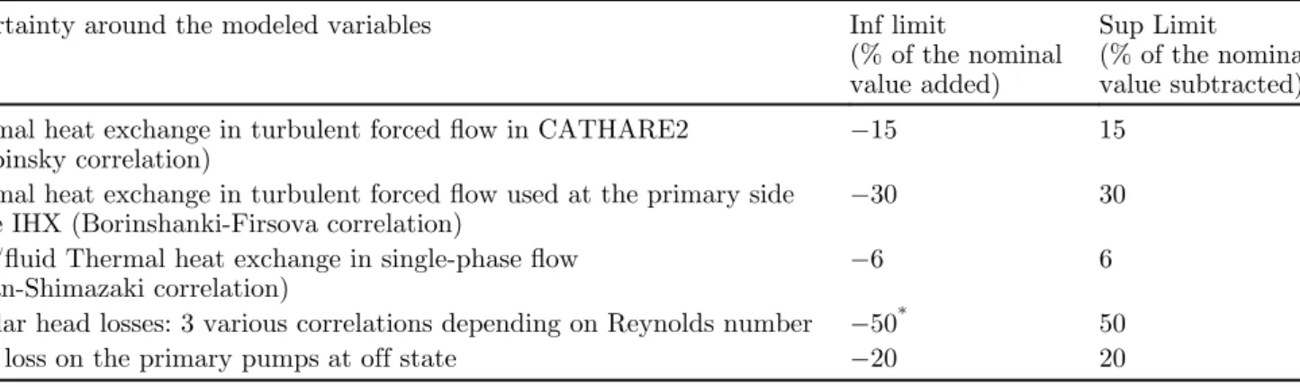
Table 7. Main model parameters uncertainties (2/2) following a uniform law. Uncertainty around the modeled variables Inf limit
(% of the nominal value added)
Sup Limit
(% of the nominal value subtracted) Thermal heat exchange in turbulent forcedflow in CATHARE2
(Shupinsky correlation)
15 15
Thermal heat exchange in turbulent forcedflow used at the primary side of the IHX (Borinshanki-Firsova correlation)
30 30
Wall/fluid Thermal heat exchange in single-phase flow (Seban-Shimazaki correlation)
6 6
Regular head losses: 3 various correlations depending on Reynolds number 50* 50 Head loss on the primary pumps at off state 20 20
*This high uncertainty range is governed by the maximal uncertainty of the 3 correlations (Blasius, Hagen-Poiseuille and Rehme correlations).
possible tendency. They clearly reveals the strong decreasing monotonic and almost linear effect of the percentage of primaryflow rate which triggers the RBH drop. The third main following influential variables are the model of regular head losses inside the sub-assemblies (to which is associated a large uncertainty) and then the singular head loss at the bottom of sub-assemblies.
This is also confirmed by an analysis of variance decomposition. The estimation of Sobol’ indices reveals that the percentage of primaryflow rate which triggers the RBH drop explains nearly 88% of the output variance, the remaining 12% is explained by the initial core power. Furthermore, there is no significant interactions between them.
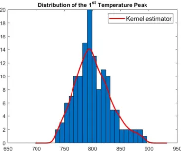
The analysis of the 136 studied scenarios reveals that 62 exceed the decoupling criterion of 800°C, that is, around 22% of cases (Fig. 7). The fractile at 95% estimated by Wilks’ formula with 95% of confidence is here equal to 880°C; thus, far above the decoupling criterion. Remember that the Wilks estimator is biased and conservative, with respect to the empirical 95%-fractile here equal to 863°C. From this result, it is possible to review the RBH design and adjust their drop triggering so that the fractile at 95% respects the decoupling criterion. To achieve this, we consider that the built surrogate model is acceptableon all the studied domain due to its high predictivity and its linear behavior according to the RBH drop criterion. We study the evolution of the fractile at 95% of thefirst clad
Fig. 6. Dependency of the cladding 1rttemperature peak to the criterion on the percentage of primaryflow rate triggering the RBH
drop (left) and the initial power (right).
Fig. 5. Evolution of the maxima of clad temperatures for the 136 simulated scenarios of USBO transient (left) and zoom on the first peak using HDR-based visualizations (right).
temperature when the probability law associated with the percentage of primaryflow rate, which triggers the RBH drop, is modified. More precisely, different nominal values (i.e. means) of this law are considered (cf.Tab. 5), while the laws of the other parameters remain unchanged. For each nominal value, the quantile is then estimated by intensive simulation of the surrogate model. Using this methodology, it appears that a nominal value of the criterion on the RBH drop higher than 54% of nominal flow rate leads to the respect of the decoupling criterion. It is recalled that currently this value is set at 45% (see Tab. 5). The distribution of the 1st temperature peak with this new criterion for RBH drop is given inFigure 8.
The second peak on the maximum clad temperature is mitigated by the onset of the natural convection inside the secondary loops. It is far less high than thefirst peak and remains always under the decoupling criterion, the
maximum obtained value being 773°C. The major variables influencing this second peak are pump inertia, initial and residual core power, and then Doppler feedback. Finally, with the lack of long term cooling, the maximum clad temperature linearly increases once the natural convection stopped at 1500 s. At term, based on results ofFigure 5, we determine when the fractile at 95%of these maximum clad temperatures reachesdurably the decoupling criterion. This time is 169 h; a 7 days grace period is available to find a cooling solution. Only the residual power influences this delay length.
5 Conclusion and prospects
In this paper, the current practice of VVUQ approach application for a SFR accidental transient is described with regard to the NSA requirements. It constitutes a practical, progressively improvable approach. A scientific tool is qualified for a given version on a given scenario, 19 transients have been identified for Sodium Fast Reactor safety demonstration. Among them, the transient related to a total unprotected station blackout has been selected for a demonstration purpose. Indeed this transient is one of the most complex in this new SFR design, involving thermal stratification and natural circulation inside the main vessel and the primary loops. Thus, it requires a multiscale coupling of several thermal-hydraulic tools to correctly capture the main safety output results. The MATHYS (Multiscale ASTRID Thermal-hydraulics) tool which features a coupling of CATHARE2 at system scale, TrioMC at component scale and TrioCFDat local scale is therefore required for this study.
This paper has presented the main steps of the VVUQ application to the qualification of the MATHYS tool on the mentioned transient focusing on the main strengths and weaknesses. The steps of verification, validation (which confronts the domain of utilization to its domain of validation and /or validity) and the quantification of various sources of uncertainties (input, scenario, model…) have been described. In addition, this work presents the propagation and post- processing of a high number of uncertain parameters, enabling to review the design of the prevention hydraulic rods. Some R&D aspects have beenaddressed as well. These aspects are related to: a methodology to confront the tool validation domain with its utilization domain through a scaling or transposition step; the development of methods to verify the reproduc-ibility of uncertainties propagation results; andfinally, as a suggestion, of new methods to quantify the validation degree of a tool and the model uncertainties from experimental results.
Glossary
BEPU Best Estimate Plus Uncertainty CFD Computational Fluid Dynamics DHR Direct Heat Removal
EMP Electromagnetic Pump GSA Global Sensitivity Analysis IET Integral Effect Tests
Fig. 7. Distribution of the 1rt
temperature peak.
Fig. 8. Distribution of the 1st
temperature peak with the new criterion for RBH drop.
IHX Intermediate Heat Exchangers IUQ Input Uncertainty Quantification MCT Maximum Cladding Temperature MNaT Maximum Sodium Temperature NSA Nuclear Safety Authority MS Mitigation Situation OS Operating Situation
PDF Probability Distribution Function
PIRT Phenomena identification and Ranking Table PP Primary Pump
PS Prevention Situation PWR Pressurized Water Reactor
RBH Hydraulically suspended absorber rod sub-assemblies
SCT Scientific Calculation Tools SDC Safety Design Criteria SET Separate Effect Tests SIT System Integral Tests SFR Sodium Fast Reactor TH Thermal-hydraulics
USBO Unprotected Station BlackOut
VVUQ Verification, Validation and Uncertainty Quantification
Authors thank RNRNA R&D project from CEA for supporting the activity.
Author contribution statement
N. Marie conceived this application of VVUQ requirements, commonly used for PWR safety demonstration, in the framework of the SFR demonstration, organized the work and summarized the results. S. Li, A. Gerschenfeld carried out the complex multi-physic simulations and A. Marrel and M. Marquès performed the statistical part of the tasks. S. Bajard, A. Tosello, J. Perez, B. Grosjean, M. Anderhuber, C. Geffray, Y. Gorsse, G. Mauger, L. Matteo participated to the application of this VVUQ methodology, working on either the verification, validation or uncertainty quantification steps.
References
1. ASN, Qualification of scientific computing tools used in the nuclear safety case 1st barrier, guide n°28, version of 25/ 07/2017. http://www.french-nuclear-safety.fr/References/ ASN-Guides-non-binding/ASN-Guide-No.-28
2. V. Larget, How to bring conservatism to a BEPU analysis, NURETH-18, Portland, OR, August 18–22, 2019
3. D. Bestion, Specific requirements for bepu methods using system thermal hydraulic codes with 3d-pressure vessel modelling, ANS Best Estimate Plus Uncertainty Interna-tional Conference (BEPU 2018) BEPU2018-194 Real Collegio, Lucca, Italy, May 13–19, 2018
4. BEMUSE Phase VI Report, Status Report on the Area, Classification of the Methods, Conclusions and Recommen-dations, NEA/CSNI/R (2011) 4, Organization for Economic Co-operation and Development/Nuclear Energy Agency (2011)
5. T. Skorek, A. De Crécy, PREMIUM—Benchmark on the Quantification of the Uncertainty of the Physical Models in the System Thermal-Hydraulic Codes, OECD/NEA/CSNI/ R(2013)8, Proc. CSNI Workshop on Best Estimate Methods and Uncertainty Evaluations, Barcelona, Spain, November 16–18 (2013)
6. R. Mendizabal et al., PREMIUM Phase V Report: Final Report, OECD/NEA/CSNI/R(2016)18, Organisation for Economic Co-operation and Development/Nuclear Energy Agency (2017)
7. H. Kamide, H. Ohshima, T. Sakai, M. Tanaka, Progress of thermal hydraulic evaluation methods and experimental sodium-cooled fast reactor and its safety in Japan, Nucl. Eng. Des. 312, 30–41 (2017)
8. R. Nakai, T. Sofu, Safety design criteria for Generation-VI Sodium-cooled Fast Reactor system, GIF Symposium, San Diego, USA, 14–15 November, 2012
9. GIF Risk & Safety Working Group, Basis for Safety Approach for Design & Assessment of Generation-IV Nuclear Systems, GIF/RSWG/2007/002, 2008
10. R. Nakai, Status of the international review on SFR SDC Phase I report and SDG development in Phase II, 5th Joint IAEA -GIF Workshop on Safety of SFR, Vienna, 23–24 June, 2015
11. Y. Okano, SFR Specific Criteria, 3rd Joint GIF-IAEA Workshop on Safety Design Criteria for Sodium-Cooled Fast Reactors, IAEA Vienna, Austria, 2013
12. S.J. Ball, S.E. Fisher, S. Basu, Next Generation Nuclear Plant Phenomena Identification and Ranking Tables (PIRTs) Volume 1: Main Report, NUREG/CR6944 Vol. 1, ORNL/TM-2007/147, Vol. 1, 2008
13. S. Li, A. Gerschenfeld, O. Bernard, T. Sageaux, Onset of natural convection in a sodium-cooled fast reactor during a station black-out: blind benchmark of safety assessment using multi-scale coupled thermal-hydraulics codes, Proceed-ings of the 18th International Topical Meeting on Nuclear Reactor Thermal-Hydraulics (NURETH 18), 18–23 August, Portland, USA, 2019
14. F. Gauche, The French Prototype of 4th Generation Reactor: ASTRID, Annual meeting on nuclear technology, Berlin, Germany, May 17 & 18th (2011)
15. F. Serre, F. Bertrand, C. Journeau, C. Suteau, D. Verwaerde, D. Schmitt, B. Farges, Status of the French R&D program on the Severe Accident Issue to Develop GENIV SFRs, ICAPP 2015, Nice, France, May 3–6, 2015
16. A. Gerschenfeld, Multiscale and multiphysics simulation of sodium fast reactors: from model development to safety demonstration, NURETH 18, August 18–23, 2019, Portland, USA
17. T. Beck et al., Conceptual design of ASTRID fuel sub-assemblies, Nucl. Eng. Des. 315, 51–60 (2017)
18. T. Beck et al., Conceptual design of ASTRID radial shielding sub-assemblies, Nucl. Eng. Des. 330, 129–137 (2018)
19. M. Saez et al., Passive Complementary Safety Devices for ASTRID severe accident prevention, International Confer-ence on Fast Reactors and Related Fuel Cycles, Yekaterinburg, Russia (2017)
20. W. Marth, The European Fast Reactor (EFR) a project of the European fast reactor cooperation, SVA-Bull. CODEN SVABB 32, 29–36 (1990)
21. G. Gaillard-Groleas et al, Improvements in simulation tools to be developed within the framework of the ASTRID project, ICAPP 2016 San Francisco, CA, USA, April 17–20, 2016 22. A. Gerschenfeld et al., Development and validation of
multiscale thermal hydraulics calculation schemes for SFR application at CEA, International Conference on Fast Reactors and Related Fuel Cycles, Yekaterinburg, Russia (2017)
23. C. Geffray et al., Results of the PHENIX dissymmetric test benchmark exercise, Proc. International Congress on Advances in Nuclear Power Plants (ICAPP 2019), 2019 24. D. Pialla et al., Overview of the system alone and system/
CFD coupled calculations of the PHENIX Natural Circula-tion Test within the THINS project, Nucl. Eng. Des. 290 (2015) 25. D. Grishchenko et al., The TALL-3D facility design and commissioning tests for validation of coupled STH and CFD codes, Nucl. Eng. Des. 290, 144 (2015)
26. A. Pesetti et al., Experimental characterization of CIRCE-HERO facility heat losses, SESAME International Work-shop, 2019
27. K.V. Tichelen, F. Mirelli, Thermal hydraulic experiments in the LBE-cooled scaled pool facility E-SCAPE, SESAME International Workshop, 2019
28. J. Pacio et al., Inter-wrapper flow: LBE experiments and simulations, NURETH18, 2019
29. H. Kamide, K. Hayashi, T. Isozaki, M. Nishimura, Investigation of core thermohydraulics in fast reactors— interwrapperflow during natural circulation, Nucl. Technol. 133, 77 (2001)
30. T. Ezure et al., Study on multi-dimensional core cooling behavior of sodium-cooled fast reactors under DRACS operating conditions, NURETH18 (paper 28311), 2019 31. Y. Wu, CLEAR-S: an integrated non-nuclear test facility for
China lead-based research reactor, Int. J. Energy Res. 40, 1951 (2016)
32. Benchmark Analysis of EBR-II Shutdown Heat Removal Tests, IAEA, Vienna, 2017
33. Benchmark Analysis of FFTF Loss of Flow Without Scram Test, Coordinated Research Project number I32011, AIEA, 2018
34. R.B. D’Auria, Scaling of the accuracy of the Relap5/mod2 code, Nucl. Eng. Des. 139, 187–203 (1993)
35. A. De Crecy, CIRCE: a tool for calculating the uncertainty of the constitutive relationships of CATHARE 2, Proc. 8th Intl Topical Meeting on Nuclear Reactor Thermal-Hydaulics, NURETH-8, 1997
36. N. Marie, A. Marrel, K. Herbreteau, Statistical methodology for a quantified validation of sodium fast reactor simulation tools, J. Verif. Valid. Uncert. (2019). https://doi.org/ 10.1115/1.4045233
37. G. Rimpault et al., The ERANOS Code and Data System for Fast Reactor Neutronic Analyses, PHYSOR 2002, Seoul, Korea, 2002
38. M. Lainet, B. Michel, J-C. Dumas, K. Samuelsson, M. Pelletier, Current status and progression of GERMINAL fuel performance code for SFR oxide fuel pins, International Conference on Fast Reactors and Related Fuel Cycles, Yekaterinburg, Russia (2017)
39. V.M. Borishanskii, E.V. Firsova, Heat exchange in separated bundles of rods with metallic sodiumflowing longitudinally, Sov. At. Energy 16, 457–458 (1964)
40. E. Skupinski, J. Tortel, L. Vautrey, Détermination des coefficients de convection d’un alliage sodium potassium dans un tube circulaire, Int. J. Heat Mass Transf. 8, 937–95 (1964) 41. R.A. Seban, T.T. Shimazaki, Heat transfer to afluid flowing turbulently in a smooth pipe with walls at constant temperature, Trans. ASME 73, 803–809 (1951)
42. A. Meynaoui, A. Marrel, B. Laurent, New statistical methodology for second level global sensitivity analysis, ASA J. Uncertain. (2019).arXiv:1902.07030
43. J. Loeppky, J. Sacks, W. Welch, Choosing the sample size of a computer experiment: A practical guide, Technometrics 51, 366–376 (2009)
44. K.-T. Fang, R. Li, A. Sudjianto, Design and modeling for computer experiments, Chapman and Hall/CRC; 1st edition (October 14, 2005), Boca Raton, Florida
45. C. Cannamela, J. Garnier, B. Iooss, Controlled stratification for quantile estimation. Ann. Appl. Stat. 2, 1554–1580 (2008) 46. E. Zio, F. Di Maio, S. Martorell, Y. Nebot, Neural network and order statistics for quantifying nuclear power plant safety margins, in: S. Martorell, C.G. Soares, J. Barnett (Eds.), Safety, reliability and risk analysis Proceedings of the ESREL 2008 Conference, CRC Press 2009, pp. 2873–2881
47. S. Nanty, C. Helbert, A. Marrel, N. Pérot, C. Prieur, Uncertainty quantification for functional dependent random variables, Comput. Stat. 32, 559–583 (2017)
48. S. Da Veiga, Global sensitivity analysis with dependence measures, J. Stat. Comput. Simul. 85, 1283–1305 (2015) 49. M. De Lozzo, A. Marrel, New improvements in the use
of dependence measures for sensitivity analysis and screening, J. Stat. Comput. Simul. 86, 3038–3058 (2016)
Cite this article as: Nathalie Marie, Simon Li, Amandine Marrel, Michel Marquès, Sophie Bajard, Annick Tosello, Jorge Perez, Baptiste Grosjean, Antoine Gerschenfeld, Marine Anderhuber, Chotaire Geffray, Yannick Gorsse, Gédéon Mauger, Laura Matteo, VVUQ of a thermal-hydraulic multi-scale tool on unprotected loss offlow accident in SFR reactor, EPJ Nuclear Sci. Technol. 7, 3 (2021)

![[PDF] Support de formation de Programmation ObjetS en PHP | Cours informatique](data:image/gif;base64,R0lGODlhAQABAIAAAP///wAAACH5BAEAAAAALAAAAAABAAEAAAICRAEAOw==)