The digital Plateosaurus II: An assessment of the range of
motion of the limbs and vertebral column and of previous
reconstructions using a digital skeletal mount
HEINRICH MALLISON
Mallison, H. 2010. The digital Plateosaurus II: An assessment of the range of motion of the limbs and vertebral column and of previous reconstructions using a digital skeletal mount. Acta Palaeontologica Polonica 55 (3): 433–458. Scientific literature and museum exhibits are full of explicit and implicit claims about the possible postures and motion ranges of dinosaurs. For the example of the prosauropod Plateosaurus engelhardti I assessed the motion range of limbs and vertebral column in a CAD program using a 3D virtual skeletal mount. The range of motion of the forelimb is very limited, allowing the grasping of objects placed directly ventrally and ventrolaterally of the anterior torso. The manus is adapted for grasping. The powerful fore limb can barely reach in front of the shoulder, making a quadrupedal walking cy− cle impractical. Only a digitigrade pose of the pes with a steeply held metatarsus is feasible, and the morphology of the stylopodium and zeugopodium indicates a slightly flexed limb posture. Hind limb protraction and retraction are limited by the pelvic architecture. The neck has significant mobility both dorsoventrally and laterally, but blocks torsion. The dorsal vertebral column is flexible to a degree similar to the neck, mainly in the anterior half, but blocks torsion totally in the anterior and posterior thirds. The anterior dorsals are similar in shape to the posterior cervicals and significantly in− crease the motion range of the neck. The tail is highly flexible due to its large number of elements, showing more lateral than dorsoventral mobility. These results are compared to reconstruction drawings and museum skeletal mounts, high− lighting a pattern of errors specific to certain widely used reconstruction methods.
K e y w o r d s : Prosauropoda, Plateosaurus, reconstruction, digital skeleton, 3D model, accuracy.
Heinrich Mallison [[email protected]], Glambecker Weg 6, 13467 Berlin, Germany.
Received 26 May 2009, accepted 25 February 2010, available online 8 March 2010.
Introduction
Plateosaurus engelhardti Meyer, 1837 from the Upper Tri−
assic of Central Europe is one of the best−known dinosaurs, with a large number of strikingly well−preserved skeletons found in Frick (Switzerland), Halberstadt and Trossingen (both Germany), and additional disarticulated finds from many other localities. P. engelhardti was also the fifth dino− saur to be described, and the first outside England (see Galton 2001). In addition to the holotype material, many skeletons were found in articulation in the first third of the 19thcentury, and the excavation of some of these was docu−
mented in detail, with figures published of the specimens as found in the ground (Jaekel 1913–1914; Huene 1926). One of the best finds of this kind, SMNS F33 from Trossingen, was prepared so that the association of all bones was re− tained, and remains in this state to this day (Fig. 1A). This specimen is the only one in which the anterior body does not rest on one side, but is upright (Sander 1992), offering insight into the articulation of the shoulder girdle difficult to gain from other specimens. Some other individuals, notably the most complete specimen ever found from Frick (MSF 23, Sander 1992), were also retained in articulation (Fig. 1B). On
the basis of this huge amount of detailed data, one could as− sume that reconstructing the overall body shape, posture and locomotion of this animal is simple. To the contrary, the liter− ature not only of the early 19th century, but even of recent
years is full of contradictory reconstruction drawings and re− marks on the locomotion of Plateosaurus. The history of biomechanical interpretations of the genus, the graphical representation of which will be discussed here, is nearly as complex and confusing as that of its taxonomy. Moser (2003) gives the latest detailed review, concluding that Plateosau−
rus is monospecific, with P. engelhardti as the sole species.
However, Moser (2003) cautions that there is ample material labeled “Plateosaurus” in collections that does not belong to the genus. Yates (2003) assigns a second, more gracile and much rarer species, previously Sellosaurus gracilis Huene, 1907–1908, to Plateosaurus as P. gracilis. Here, “Plateo−
saurus” refers to the Halberstadt, Trossingen, Ellingen (Ger−
many) and Frick material belonging to P. engelhardti. The easiest way for a researcher to communicate his view of the body shape, locomotion and general appearance of an extinct animal is usually the creation of a reconstruction drawing. The tradition goes back to Marsh (e.g., Triceratops and “Brontosaurus” in Marsh 1891), and in recent years, in−
clusion of such a drawing in publications has almost become
de rigueur. A certain standard has developed: the animals are
depicted in lateral view, with the bones drawn as outlines, and a suggested body outline surrounding them in black. Other views, dorsal, anterior or cross−sections, are some− times also provided (e.g., Paul 1996, 2000). Some artists and researchers offer “rigorous” drawings of specific specimens, in which the preserved parts are hatched (e.g., Wellnhofer 1994), so that the viewer can judge what is actually know from the fossil and what is inferred from other finds of the same or similar species. This distinction is not moot, as shown by Therrien and Henderson (2007), because many an− imals do not scale linearly compared to their close relatives, so that linear scaling will deliver inaccurate size and mass es− timate.
The first reconstruction drawing of Plateosaurus can be found in Jaekel (1913–1914). Most famous, though, is the drawing in Huene (1926: pl. 7). It depicts SMNS 13200, a nearly complete skeleton of “P. quenstedti”, a junior synonym to P. engelhardti (Galton 1985). The animal is shown in lateral view, in a bipedal pose with a steeply inclined body, appar− ently running quickly. Galton wrote a series of publications on
Plateosaurus and related prosauropods, several of which
(Galton 1971b, 1986a, 1990, 2000, 2001) also contain lateral view drawings. Those in Galton (2000) and (2001) are copies of that in Galton (1990), which is based on Huene (1926), as stated in Galton (2001) and some print editions of Galton (2000). The drawings in Galton (1971b) and (1976) are exact depictions of the museum mount of AMNH 6810. Weis− hampel and Westphal (1986) published a guide to the Plateo−
saurus exhibit in the IFGT, which contains a drawing in lateral
view. Wellnhofer (1994) describes material from Ellingen in Bavaria. His “rigorous” drawing depicts Plateosaurus in a quadrupedal pose, with a tail base bent sharply downward.
Plateosaurus receives an extensive figure treatment by Paul
(1987, 1997, 2000). A lateral view of the skeleton with body outline, apparently in a rapid walk, is supplemented by a dor− sal view and a drawing combining an anterior view at the level of the pectoral girdle and a posterior view at the level of the pelvic girdle, in the same pose. A second lateral view portrays the animal as a musculature reconstruction in a full gallop, with the pedes almost overstepping the manus. On request, Scott Hartmann (www.skeletaldrawing.com) provided a res− toration drawing in lateral view. Skeletal restorations dis− cussed below are reproduced in Fig. 2.
The public’s perception of an extinct animal is shaped more by mounted skeletons in museums than by scientific publications. Due to the distribution of Plateosaurus through− out Central Europe, mounted skeletons or casts can be found in Frick (MSF), München (BSPG), Tübingen (IFGT), Stutt− gart (SMNS), Frankfurt (SNG), Halberstadt (MHH) and
Berlin (MFN). The IFGT houses two mounts. GPIT1 (Fig. 1D), the source data for the virtual skeletal mount (Fig. 1E) employed in this study, is a nearly complete individual mounted in a bipedal standing pose, snout close of the ground as if feeding or drinking (see Gunga et al. 2007; Mallison 2007, 2010). GPIT2 is a composite of similar size to GPIT1. It consists of two individuals, one consisting of a skeleton nearly complete to the level of the last dorsal, the other lacking all parts anterior to the pelvis. Several copies of mounts can be found in other museums worldwide. Some of the mounts have been altered or taken down in recent years. For example, the SMNS housed a total of four mounted casts of SMNS 13200, in a variety of poses (Ziegler 1988: cover illustration, fig. 4; Moser 2003: fig. 4). All but one in a quadrupedal walking pose (Fig. 1H, G) have been taken down for an exhibition redesign in 2007. Similarly, the MFN mount has been dismantled and not been recreated because of a museum renovation in 2006/2007. The lizard−like sprawling old mount of SMNS 13200 (Fraas and Berckhemer 1926) in the old Stuttgart mu− seum was dismantled during World War II and never re− mounted. Outside Europe, the AMNH mount of a nearly com− plete Trossingen skeleton (AMNH 6810; Fig. 1F) from the joint 1921–1923 excavation has been used by most US re− searchers as the typical Plateosaurus. I here only discuss mounts that I was able to inspect personally, including mounts that have since been taken down, as reliance on photographs alone is prone to cause errors.
Even more memorable than drawings or mounts, but more difficult to assess for their accuracy, are models of the living animal. In a tradition going back to Benjamin Water− house’s plaster dinosaurs created for Richard Owen in 1851 and exhibited in the Crystal Palace (London, UK), many mu− seums today enliven their exhibits with life−sized models. In the SMNS, the old skeletal mounts were accompanied by two models, one in a tripodal (Fig. 1C) and one in a quadru− pedal pose, at the scale of the largest Plateosaurus ever found. Together with the new skeletal mounts, new 3D mod− els were set up in 2007, in quadrupedal (Fig. 1I, L), bipedal (Fig. 1J) and a resting pose. Additionally, toy versions of the old tripodal and the new quadrupedal (Fig. 1K) models (by BullylandTM) are available, which were created in collabora−
tion with scientific advisors from the SMNS. While their small size leads to inaccuracies in some areas for technical reasons, they are overall proportioned almost like the life− sized models. They can stand in their stead for the analysis here, because they can be digitized accurately and thus help avoid the inherent inaccuracies of photograph analysis due to perspective distortion.
In addition to these classic reconstructing methods, digi− tal techniques have also been used in recent years. Gunga et al. (2007, 2008) used high resolution laser scanning to obtain
Fig. 1. Prosauropod Plateosaurus engelhardti Meyer, 1837 skeleton mounts and life reconstructions. A. SMNS F33, in position as found. B. MSF 23, in posi− tion as found. C. SMNS old tripodal model. D. GPIT1. E. GPIT1 virtual mount based on CT data. F. AMNH 6810. G, H. SMNS 13200 (cast). I, L. SMNS new quadrupedal model in anterior (I) and lateral (L) views. J. SMNS new bipedal model. K. Toy model of SMNS new quadrupedal model by Bullyland™. All but I femur/thigh length ~0.6 m, I ~5 m high. Photographs by the author except C ©GPIT. A, C–K from Trossingen, Germany, B from Frick, Switzerland.
3D point cloud models of various mounted skeletons, includ− ing the mount of GPIT1 in the IFGT. Based on this excellent base they created two versions of a digital 3D model, one in− tentionally fat, the other slim, to assess the possible range of soft tissue reconstruction.
With all kinds of reconstructions it is important to provide a high level of accuracy. Pictures and models tell an “at one glance” message about an animal’s body shape and propor− tions that immediately tells the viewer much more than just the shape and sizes of the actual (bony) specimen. Small in− accuracies can lead to drastic misinterpretations. A simple example is Henderson (2006), who used a drawing by Paul (1987) to create a 3D model of Plateosaurus, based on which the total mass and the center of mass position were calcu− lated. For unknown reasons, the scale bar in the figure by Paul (1987: 29) appears in altered form in Henderson (2006: fig. 11). In fact, the size of the animal is considerably reduced by this small change, so that Henderson calculates a body weight of only 279 kg for Plateosaurus (Henderson 2006: table 4). The scaling difference is not immediately visible, so that there is a high risk that other researchers will use
Henderson’s mass value as the body weight of an adult
Plateosaurus in future works. Similarly, the many drawings
and skeletal mounts of Plateosaurus in a quadrupedal pos− ture have led to an increasing number of artists’ reconstruc− tions in similar poses. Today the internet is a prime research tool for scientists and laypeople alike. Practically every internet site offers pictures with their text (or vice versa), and there is the increasing trend to reduce the text and emphasize the visual presentation. This means that pictures gain in im− portance relative to textual descriptions. Thus, inaccurate figures can have a profound influence on both the public’s and the scientific community’s perception of an extinct animal, and should be avoided at all cost.
An animal’s range of motion, especially in limb joints, determines motion capabilities such as grasping ability or possible stride length. For an assessment of locomotion capa− bilities, it is of paramount importance to consider the motion ranges of the humerus and femur, as well as the ability to pronate the hand. Also, the lateral stiffness or flexibility of the vertebral column can provide insight into the animal’s ability to use undulating motions for locomotion, either on
Fig. 2. Skeletal reconstructions of prosauropod Plateosaurus engelhardti Meyer, 1837, redrawn from: A. Paul (1987, 2000). B. Wellnhofer (1994). C. Jaekel (1913–1914). D. Huene (1926). E. Galton (1990). F. Weishampel and Westphal (1986). G. Scott Hartmann. (www.skeletaldrawing.com). Typical femur length of Plateosaurus is 0.6 to 0.8 m.
land or in water, while dorsoventral bending influences stride length during galloping and leaping. To date, detailed discus− sions of the mobility of extinct dinosaurs are limited almost exclusively to theropods, with an emphasis on their fore− limbs (e.g., Galton 1971a; Carpenter and Smith 2001; Gishlick 2001; Carpenter 2002; Senter and Robins 2005; Senter 2006a, 2006b; Senter and Parrish 2006). Sauropodo− morphs are rarely treated in detail, with the exceptions of, for example, Galton 1971a (Plateosaurus), or the discussion of manus pronation capabilities in Plateosaurus and Masso−
spondylus in Bonnan and Senter (2007).
Here, I address the mentioned reconstruction drawings, mounts and 3D models with regards to accuracy, attempting to determine which factors have the strongest influence on accuracy. Also, I test claims about joint motion range, using the 3D virtual skeleton of GPIT1. This method is much easier to use than manual manipulation of casts or real bones, as e.g., conducted by Senter and Robins (2005). Aside from al− lowing extensive study without the risk of damaging the specimens, it also can be performed without access to the material, once it has been digitized. Also, there is no need to create elaborate support for the bones in larger assemblages (see Senter and Robins [2005: fig 1] for an example concern− ing a theropod forelimb). Claims about motion range can be explicit, e.g., Paul (2000: 83): “[in] most bipedal dinosaurs […] the lower arm bones, radius and ulna, could rotate around each other”, they can be implicit in a drawing (e.g., showing a strongly dorsiflexed neck), or even in a remark on locomotion or behavior of the animal, e.g., Paul (2000: 91): “The long−backed prosauropods may have run with a bound− ing gallop, but the heavily built, shorter−footed melanoro− saurs probably galloped less and trotted more”. This implies that Plateosaurus was capable of quadrupedal locomotion, did not have a sprawling gait, and could use gaits with unsupported phases.
Institutional abbreviations.—AMNH, American Museum of
Natural History, New York, USA; BSPG, Bayerische Staats− sammlung für Geologie und Paläontologie, München, Ger− many; GPIT, see IFGT; IFGT, Institut für Geowissenschaften, Eberhardt−Karls−Universität Tübingen, Tübingen, Germany (collection numbers: GPIT); IPFUB, see FUB; FUB, Freie Universität Berlin, Germany (collection numbers of osteolo− gical collection IPFUB OS); MB.R., see MFN; MFN, Mu− seum für Naturkunde – Leibniz−Institut für Evolutions− und Biodiversitätsforschung an der Humboldt−Universität zu Berlin, Berlin, Germany (collection numbers: MB.R.); MHH, Museum Heineanum Halberstadt, Halberstadt, Germany; MSF, Sauriermuseum Frick, Frick, Switzerland; SMA, Saurier− museum Aathal, Aathal−Seegräben, Switzerland; SMNS, Staatliches Museum für Naturkunde Stuttgart, Stuttgart, Ger− many; SNG, Senckenbergische Naturforschende Gesell− schaft, Frankfurt, Germany.
Other abbreviations.—ONP, osteologically neutral pose.
Two vertebrae are in ONP if their centra faces are parallel and the zygapophyses overlap fully.
Material
For creation of the virtual mount of Plateosaurus, the nearly complete individual GPIT1 was CT−scanned at the UHT by Burkhard Ludescher. Scanning and file extraction details are given in Mallison (2010). Several elements of GPIT1 are missing or severely damaged. Where possible these were re− placed with CT−scan based files from GPIT2, a composite skeleton from the same excavation and of similar size (see Huene 1926, 1928, 1932). These include the whole left manus, and in order to avoid misinterpretations on the proper articulation and the motion range of the wrist, the entire left forelimb of GPIT2 was used. Also, the left pes was mirrored and used in stead of the right pes, in which most metatarsals are incompletely preserved. Several elements are missing in both GPIT1 and GPIT2, or so incompletely preserved that they are not useful for the work presented here. These are: both clavicles, all cervical ribs not attached to the cervical verte− brae, and the sternals. The gastralia could not be scanned due to being embedded in large sediment slabs. Results concern− ing missing, deformed or potentially deformed elements of GPIT1 and GPIT2 were compared to other individuals of
Plateosaurus, both from Trossingen and Halberstadt. These
include SMNS F33 (Fig. 1A), MB.R. 4429, an articulated neck with skull from Halberstadt, MSF 23 (Fig. 1B), and SMA unnumbered, an articulated neck with partial skull and the first six dorsals from Frick. These and other specimens, as well as the diagram of GPIT1 as found in the field by Huene (1928: pl. 10) were also used for assessing the correct articulation of the skeleton, especially the manus and pes, and the possible mo− tion range of the neck.
The 3D files (Polymesh [*.stl] format) are available on re− quest from the author, providing previous permission for use by the IFGT.
Methods
Computer programs and digitizer
All CAD tasks (mounting the skeleton, motion range analy− sis) were conducted using McNeel Associates Inc. “Rhinoc− eros® NURBS modeling for Windows®” versions 3.0 and 4.0. Digitizing of toy models also took place in Rhinoceros©, using an ImmersionTMMicroscribe 3D digitizer. The result−
ing point clouds were meshed in Geomagic Inc. Geomagic Qualify 8.0© (time limited evaluation version).
Methods of CAD virtual skeleton creation and
range of motion assessment
The virtual skeleton of GPIT1 was created in a bipedal stand− ing pose (Mallison 2010). For the assessment of mobility, those elements of importance to the joint being investigated (e.g., two consecutive vertebrae or humerus, radius and ulna)
were copied into a new Rhinoceros® file. One object was given a different color and made immobile (“locked”), the other one duplicated and moved to an extreme position (e.g., maximum dorsiflexion). Other copies were moved into fur− ther extreme position (e.g., extreme lateral flexion) until all possible positions had been created. Combinations of ex− tremes (e.g., maximum lateral flexion at maximal dorsi− flexion) were also created. Throughout the process, the artic− ulation of the elements was checked in six axial views and a freely rotatable perspective view. Where necessary, objects were made translucent to allow better judgment of the feasi− bility of the created articulation. Angles were measured in the CAD program either directly using bone landmarks, or by adding a line to the bone before motions were tested, copying and moving this line with the bone, and then mea− suring the angle between the two lines. The resulting files for each motion between vertebrae were imported into one new file, to illustrate e.g., maximum dorsiflexion of the entire dor− sal vertebral column. Similarly, for the limbs the files from stylopodium, zeugopodium and autopodium were united. Here, all non−redundant positions were combined, to illus− trate the total motion range of the limb.
Motion between vertebrae was assumed to be possible if any zygapophysal overlap was retained. This means that in contrast to Stevens and Parrish (1999, 2005a, b), 50% over− lap is not required. Stevens and Parrish (1999) use this value, but as they point out (Stevens and Parrish 2005a), giraffes re− tain only minimal overlap, and avian cervicals retain be− tween 25% and 50% of overlap. Here, minimal overlap is therefore used, and the resulting position then assessed for its feasibility. Overlap of 50% is used when higher values lead to unrealistic results as mentioned below.
Influence of soft tissues on the range of motion
Ligaments, muscles and tendons.—Aside from the bones, soft tissues have a large influence on the motion range of joints. For example, ligaments play an important role in block− ing or strictly limiting certain degrees of freedom in many joints (McGinnis 2004; Stevens and Parrish 2005a). Some− times these limitations are obvious from the bone shapes. For example, the shape of the distal condyles of the human femur indicates that the knee is, as a first approximation, limited to flexion/extension only, even though the bones alone would al− low other motions such as antero−posterior sliding. Similarly shaped femora in extinct animals can thus be assumed to have had a similar complement of ligaments, and the knee therefore a similarly limited amount of degrees of freedom. If insertion sites of ligaments can be found on the fossil, and the corre− sponding ligament in extant taxa reliably identified, the accu− racy of a motion range analysis can increase, but in the case of
Plateosaurus few traces were found, and no corresponding
ligaments could be identified with certainty.
Muscles and their tendons can also limit motions (McGinnis 2004), because they cannot be stretched at will. The greater the distance between a muscle’s path and the joint
it works on, the lesser the angle the moved body part can cover. The prime example is the caudofemoralis longus mus− cle, running from the underside of the anterior tail to the fourth trochanter of the femur. Its moment arm on the hip is accord− ingly large, and the more distal position of the fourth tro− chanter in dinosaurs compared to lizards and crocodiles means that the angle the femur can cover is smaller. The exact rota− tion angle, however, depends on many unknown variables, among them the internal structure of the muscle (parallel− fibred or pennate?), the relative length of its tendon, and the path both take through other soft tissues, so that the resolution that can be achieved by modeling the muscle is insufficient to be of help for a range of motion study (contra Paul 2005). In such cases evidence from skeletons found in life−like posi− tions can help determine minima for joint deflection angles. Many skeletons of Plateosaurus were found belly down, with strongly flexed hind limbs, e.g., MSF 23 (Fig. 1B) and espe− cially SMNS F33 (Fig. 1A). Although sediment compaction has compressed SMNS F33 to the point where the femur, tibia and metatarsus are in contact with each other along the bone shafts, it is reasonable to assume that Plateosaurus could in− deed adopt a resting pose in which the pelvic girdle supported part of the animal’s weight. SMNS F33 can be used to recon− struct this position, by attempting to place the digital skeleton into the same pose without disarticulating any joints. Where this is not possible the digital bones must be placed in the clos− est possible position that is dorsoventrally of greater extent, because SMNS F33 was mainly dorsoventrally compressed. The resulting pose of the digital skeleton (see below) is then the best estimate for the posture SMNS F33 had before sedi− ment compaction. The resulting protraction angle of the hind limb and the flexion angle of the knee and ankle are required minima. In the following, if angles determined using this or similar approaches are smaller than those suggested by bone− bone articulation, the smaller angle is given.
Motion range limitations are especially important and dif− ficult to determine from the bones alone where muscles or tendons cross more than on joint. The maximum length of the muscle may be insufficient to allow full range of motion in all joints, effectively reducing the range of motion, while sin− gle−joint muscles rarely do so (McGinnis 2004). For exam− ple, Crocodilus porosus (IPFUB OS 13) shows limits of about 13° per joint in the tail for lateral flexion based on the bones alone at 50% zygapophsal overlap and 22° with mini− mal overlap, but is limited to roughly 6° per joint when the complete tail is flexed to one side, based on measurements of overall curvature of the tail on photographs (Fig. 3A; own unpublished data). In contrast, if the tail is placed in a sinu− soidal curve, so that e.g., only ten articulations flex to the left, and the following ten flex to the right, the soft tissues do not reduce the maximum angle as much, allowing 10° of motion per joint (own unpublished data). The osteoderms of croco− diles have an even larger influence blocking flexion and ex− tension of the trunk. Overall, Crocodylus porosus is capable of roughly a 45° extension in the dorsal series (own unpub− lished data), while the vertebrae alone would allow more
than 90°. The influence of soft tissues on the motion range of a joint depends on many factors, and cannot be taken into ac− count in detail here, especially because there is no direct fos− sil evidence of soft tissues known in Plateosaurus.
Articular cartilage.—Especially difficult to estimate is the influence of articular cartilage on joint motion. In many joints of dinosaurs, including Plateosaurus, the amount of cartilage was small, comparable to extant mammals and birds. Especially in the digits and along the vertebral column there are well developed bony articulation surfaces, so that good matches exist between the bones. However, the ends of limb bones as well as the articular edges of e.g., the scapulae, coracoids and sternals retained a large amount of cartilage, so that the shape of the preserved bone may not correlate closely to the actual articulation surface. In general, there appears to be a good correlation of the general shape and main features (but not the fine details) in adult archosaurs, but juveniles of all and adults of some selected taxa show massive differ− ences (Bonnan et al. 2009; own unpublished data). Cartilagi− nous tissues are rarely preserved on fossils, so the thickness of cartilage caps in dinosaurs is unclear. Often, it is claimed that even large dinosaurs had only thin layers of articular car− tilage, as seen in extant large mammals, because layers pro− portional to extant birds would have been too thick to be ef− fectively supplied with nutrients from the synovial fluid. This argument is fallacious, because it assumes that a thick cartilage cap on a dinosaur long bone would have the same internal composition as the thin cap on a mammalian long bone. Mammals have a thin layer of hyaline cartilage only, but in birds the structure is more complex, with the hyaline cartilage underlain by thicker fibrous cartilage pervaded by numerous blood vessels (Graf et al. 1993: 114, fig. 2), so that nutrient transport is effected through blood vessels, not diffu− sion. This tissue can be scaled up to a thickness of several centimeters without problems.
An impressive example for the size of cartilaginous struc− tures in dinosaurs is the olecranon process in the stegosaur
Kentrosaurus aethiopicus Hennig, 1915. In the original de−
scription a left ulna (MB.R.4800.33, field number St 461) is figured (Hennig 1915: fig. 5) that shows a large proximal process. However, other ulnae of the same species lack this process, and are thus far less distinct from other dinosaurian ulnae (Fig. 3B, C). The process on MB.R.4800.33 and other parts of its surface have a surface texture that can also be found on other bones of the same individual, and may indi− cate some form of hyperostosis or another condition that leads to ossification of cartilaginous tissues. Fig. 3B–D com− pares MB.R.4800.33 and two other ulnae of K. aethiopicus from the IFGT skeletal mount. It is immediately obvious that the normally not fossilized cartilaginous process has a signif− icant influence on the ability to hyperextend the elbow, be− cause it forms a stop to extension. Similarly large cartilagi− nous structures may have been present on a plethora of bones in any number of dinosaur taxa, so that range of motion anal− yses like the one presented here are at best cautious approxi− mations.
Methods for comparing the virtual skeleton
to previous reconstructions
For comparison of a reconstruction drawing to the virtual skeleton, the drawing was imported into Rhinoceros© as a background image and scaled to fit the virtual skeleton. If possible, a fit was created for the overall length of the dorsal series and the femur length. If this was not possible due to differences in proportion, the dorsal series alone was used. Initial attempts to include the sacral series as well failed, be− cause of different deformations of the sacra of GPIT1 and SMNS 13200, the latter of which is the base for most recon− struction drawings. If there were several views of a recon−
Fig. 3. Examples for the influence of soft tissues on joint motions. A. Outline drawing of caudals 5 and 6 of salt−water crocodile Crocodylus porosus, IPFUB OS 13 in dorsal view. Anterior is up. Caudal 6 is shown in positions with full, 50% and minimal zyapophysal overlap (0°, 10°, 21°, respectively). Width of caudal 5 across transverse processes is 113 mm. B–D. Ulnae of stegosaur Kentrosaurus aethiopicus Hennig, 1915 from the Upper Jurassic Tendaguru For− mation of Tanzania, in anterior (B1–D1) and lateral (B2–D2) views. Right (B, field number St [unknown]) and left (C, field number St 113) ulnae, both part
of GPIT 1424 (mounted skeleton). D. Left ulna (part of skeletal mount in MFN) MB.R.4800.33 (length 306 mm) shows cartilage preservation on the distal and especially proximal end, preserving a large olceranon process.
struction available, they were imported into one Rhinoc− eros© file and arranged as background images in the appro− priate axial viewports (dorsal view in the “top” viewport, an− terior view in the “left” viewport, etc.). The virtual skeleton was then posed to conform to the drawing as well as possible. In case of length differences between bones, the virtual bone was shifted to the proximal/anterior end of the corresponding element in the drawing, creating a visible gap in the next dis− tal articulation. Ribs were ignored in most cases, due to the relatively high degree of deformation in the ribs of GPIT1, and the usually quite schematic style of the ribs in the draw− ings. The sole exception is the set of drawings by Paul (1987, 1997, 2000). Paul considers his drawings “technical recon− structions”, even when they are based on old photographs of mounts, and uses them for taxonomic investigations (Paul 2008). Clearly, these drawings must thus conform to higher standards than others that are created purely for illustrating general proportions of the animal. In the case of multiple views, the bones were first arranged according to the lateral view, then in the other views. If this required misaligning them in lateral view, a duplicate was created instead. The re− sulting pose was assessed in all axial and the perspective views.
Skeletal mounts in museums were inspected for correct articulation visually and on photographs. Because several mounts were visited several years ago, before the conception of the work presented here, and have since been dismantled, their assessment was based on photographs alone. Here, and for life−sized 3D models, the problem of edge distortion had to be solved. Where possible, a number of photographs were taken with a 50 mm lens from a fixed distance at a right angle to the long and transverse axes of the mount or model, a 25% frame cut away from them, and the remaining, least distorted central parts combined into a composite image. Alterna− tively, a 300 mm lens was used to take one picture at a large distance. While these photographs are more distorted than a composite picture, they are better than a wide angle shot from a short distance.
One problem that could not be solved easily unless at least two orthogonal views were available is that of perspec− tive distortion in dynamically posed mounts. If, e.g., the neck or tail curves towards or away from the viewer, they will ap− pear shorter than they really are. This effect is hard to judge in lateral view alone. Where no picture from another perspec− tive was available, I forced the virtual skeleton to fit the lat− eral view. This may hide articulation errors in the mounts or scaling errors in the models.
The digital 3D models were imported into Rhinoceros© directly, while the toy models were first mechanically digi− tized using the point cloud digitizing procedure detailed in Mallison at al. (2009), and meshed to create a 3D body in Geomagic Qualify 8.0©. The virtual skeleton was arranged to conform to them in the same way as for multiple view draw− ings. The 3D models by Gunga et al. (2007) were compared directly to the point cloud scan file of the IFGT GPIT1 skeletal mount, on the basis of which the models were created.
Results
Range of motion
In the following, maximum motion ranges with (where nec− essary) considerations of forces acting on articulations will be discussed for separate functional body units, such as the hindlimb or the tail. Note that the determined motion ranges are the extremes possible for these parts alone, not for the en− tire skeleton. In some joints, motions are possible to degrees that are blocked by other body parts given certain articulation angles of other joints. These combined motion ranges are dis− cussed afterwards.
Vertebral column: cervical series.—Plateosaurus has 10 cervical vertebrae (plus a rudimentary proatlas), 15 dorsals and three sacrals (Huene 1926). Huene (1926) also lists 41 preserved and at least 15 missing distal caudals for SMNS 13200. In GPIT1 45 caudals are present, and only a very small number may be missing at the tip of the tail. Atlas and axis of GPIT1 are attached to the skull and were not available for CT scanning. For reference, the cervical column was placed so that the neural canal of the last vertebra was hori− zontal. The neck was mounted in neutral pose (following Stevens and Parrish [1999], the pose with perfectly overlap− ping zygapophyses and parallel centra faces is often also termed osteologically neutral pose [ONP]), although there are strong indications that the posture has no special signifi− cance for an animal’s habitual posture (Christian and Dzem− ski 2007; Taylor et al. 2009). In lateral view the neck then projects upwards slightly, forming a 7° angle between the horizontal and the line connecting the posterior opening of the neural canal on the last and the anterior one on first pre− served cervical. However, there is no marked angling of the centrum−centrum articulations at the base of the neck, nor marked keystoning. Rather, the centra are trapezoidal in lat− eral aspect, with the anterior face dorsally displaced in rela− tion to the posterior face. This shift is present in all but the first two cervicals, “stepping up” the neck while the inter− vertebral discs are parallel to each other. The anterior three cervical centra are slightly keystoned, creating a ventrally concave arch that places the anterior surface of the centrum of the epistropheus in a near vertical position. The shape of the atlas and its articulation with the epistropheus result in a downwards inclined position of the skull, as described by Huene (1926: 28).
Any definitive assessment of neck mobility requires knowledge of the shape and potential flexibility of the cervi− cal ribs. These, however, are not fully preserved in GPIT1 to− day, and have not been prepared separately in other individu− als of Plateosaurus. Several articulated necks have been re− tained in the position they were found in. Especially well pre− served are SMNS F33, SMA unnumbered, and MB.R.4429. Of these, SMNS F33 and MB.R.4429 curve strongly, are well articulated, and their cervical ribs are distally slightly bent, indicating some flexibility in vivo. Although the cervi−
cal ribs in Plateosaurus overlap the next vertebra, it is un− likely that they blocked intervertebral motion. For the digital analysis presented here I therefore ignored them, instead comparing my results to the articulated necks.
Ventral mobility of the neck is limited to a 100° curve, measured as the angle between the anterior face of cervical 2 and the posterior face of cervical 10. Mobility is greatest be− tween the anterior vertebra, and decreases with the reducing length of the vertebrae posteriorly. In the posteriormost three cervicals, ventriflexion is minimal, both because of the dorsal displacement of the zygapophysal articulation, and the trape− zoidal shape of the centra. Dorsiflexion is possible to a slightly
larger extent (110°), with the posterior half of the neck con− tributing the largest part. The anterior part is in comparison quite stiff (Fig. 4A).
Lateral motions of the neck cannot be accurately judged because of the imperfect preservation of the cervical ribs. However, a 180° curve appears plausible as a minimum, plac− ing the head 0.6 m laterally and 0.3 m above the neck base, with the snout pointing caudally (Fig. 4B). SMNS F33, MB.R.4429, and MSF 23 do not contradict this interpretation. All are less flexed than appears possible from the virtual mount, but all also appear not to be flexed to the limits of the intervertebral joints. An articulated neck in the SMA (unnum−
Fig. 4. Range of motion of prosauropod Plateosaurus engelhardti Meyer, 1837 using the digital skeleton mount of GPIT, from Trossingen, Germany.
A. Lateral view of cervicals in neutral articulation, maximal dorsiflexion and maximal ventriflexion. B. Dorsal view of cervicals in neutral articulation and maximal lateral flexion. C–F. Dorsal vertebral column and ribcage in dorsal view in maximal lateral flexion (C), lateral view in maximal ventriflexion (D), lateral view in maximal dorsiflexion (E); air exchange volume determination (F). Pink ribs and dark green volume = exhaled volume, red ribs and translu− cent green volume = inhaled volume. See text for further explanation. G. Tail in lateral view, showing (top to bottom) dorsiflexion at 10° and at 5° per joint, neutral articulation, maximum ventriflexion. H. Tail in dorsal view, straight and at 10° lateral flexion. Length of cervical series 103 cm, length of dorsal se− ries 137 cm, length of caudal series 261 cm. Anterior to the left in A–C and F–H, to the right in D and E.
bered) from Frick shows a similar curvature as SMNS F33, al− though created by both dorsiflexion and lateral flexion. Galton (2001: fig. 1c) figures the skeleton of AMNH 6810 as found based on an unpublished drawing by Friedrich von Huene. Its neck is curved ~180°, with the largest flexion angles occurring in the middle part of the neck. However, it is not clear whether these vertebrae are still articulated. In all, it seems reasonable to assume that the values given above are possible, but a slightly more restricted range of motion cannot be ruled out. Torsion is almost totally blocked by the medially angled zygapophysal articulations along the entire neck.
Vertebral column: dorsal series.—ONP articulation creates a slight dorsally concave arch in the anterior five dorsals, and a slight ventrally concave curve in dorsals 6 to 10. From dorsal 11 on, the series is straight. As in SMNS 13200, the zygapo− physal faces of GPIT1 are medially inclined about 45° be− tween dorsals 1 and 2, measured by placing a rectangle on the articulation surface of each side in the CAD program, and hav− ing the program calculate the angle this plane forms with the vertical axis. From dorsal 3 on, the zygapophyses are oriented progressively less steep up to dorsal 6, where the angle is about 18°. Further posteriorly, they are oriented more steeply again, and reach approximately 35° between dorsal 15 and the first sacral. This angle is 10° lower than in SMNS 13200. It is unclear whether this difference is caused by intraspecific vari− ation or deformation. The angles for GPIT1 were determined on the right side only, because the lateral processes and zyga− pophyses of the left side are all displaced dorsally by post− mortem deformation. The zygapophysal alignment indicates a high mobility in dorsoventral direction in the posterior and even more so in the anterior third of the dorsal series. The mid− dle part is somewhat less flexible in dorsoventral direction, and additionally allows strong lateral flexion. Torsion is blocked by steeply oriented zygapophyses, and thus only pos− sible, to a limited degree, in the middle third of the dorsal se− ries. Articulation of the digital files confirms this interpreta− tion. However, lateral flexion of the vertebrae alone is possible to an extent that appears unreasonable, allowing nearly a full circle for the entire dorsal series. Lateral flexion between con− secutive vertebrae of over 30°, as possible between, e.g., dor− sals 7 and 8, leads to intersection of the ribs. Apparently, lat− eral motion in vivo is not blocked osteologically, but rather by the maximum compression of the intercostal tissues. Addition of the ribs to the 3D file leads to a maximum lateral curvature of the dorsal series of about 110° (Fig. 4C). Flexion is also blocked by the ribs, not the intervertebral articulations, allow− ing a 85° curve (Fig. 4D). Extension was limited by the inter− costal and ventral soft tissues, the effect of which is difficult to determine. However, a 90° curve for the entire dorsal series seems possible (Fig. 4E). In life, the dorsal mobility of the an− terior dorsals was certainly greater, as rib motion was ignored here. This would have increased the motion range of the neck by moving the neck base.
Ribcage.—The ribs of GPIT1 all show the marks of post− mortem deformation and distortion. Comparison between
contralateral elements shows that this damage is not signifi− cant enough to make a reconstruction of the ribcage width impossible. The capitulum can be matched accurately with the parapophysis in most ribs, but the dorsal displacement of the left transverse processes of many dorsal vertebrae results in a dorsal displacement of the diapophysis (term used here sensu Huene [1926] and Wilson [1999], referring to the artic− ulation surface, not the entire transverse process). In some dorsals, the tuberculum cannot be articulated with it at all, in others the resulting position elevates part of the rib shaft as high as the top of the neural arch. Similarly, on the right side some neural arches, and with them the diapophyses, have been displaced ventrally. Here, the respective ribs are tilted medially. In the virtual skeleton an attempt was made to cor− rect for these errors, placing the ribs as symmetrically as pos− sible. This results in a high−oval ribcage cross−section, in which the transverse axis at the widest point (dorsal 6) is slightly shorter than the vertical axis, if the latter is measured from the ventral end of the corresponding rib. The 4th to 9th ribs are almost equal in length, and the cross sections only slightly less wide than in the 6th. Fitting an ellipse into the rib pairs of this region results in a ratio between the transverse and the vertical axis of 0.85. In the first to third rib pairs a greater difference exists between the axes of the ellipse, with the transverse axis roughly 0.6 times the length of the vertical axis. The posterior third of the ribcage is only slightly wider than the anterior third, but the ribs are much shorter. Their distal ends form a posteriorly ascending line that corresponds to the pubes.
While the correct angle between the longitudinal axis of the animal and the rib shafts cannot be determined with ease, it is nevertheless possible to estimate the tidal volume of
Plateosaurus on the basis of the reconstructed ribcage. As in
tyrannosaurids (Hirasawa 2009), the ribs rotate around an axis defined by the articulations between capitulum and parapophysis, and tuberculum and diapophysis. The orienta− tion of these axes is one of the main factors defining thorax kinematics. The axes of rotation were determined by creating cylindrical bodies that were arranged with one end touching the diapophysis and the other end the parapophysis. Five point objects were created on the medial side of each rib, splitting the medial face of the rib into four segments, and grouped with the rib, so that any motion of the rib also affects the points. All ribs were rotated around their respective artic− ulation axes by +5°, while a copy of each rib (with the at− tached points) was rotated by −5°, creating a 10° difference between the two rib sets. This angle results in rib kinematics similar to those observed during rest or moderate activity in extant basal birds (Claessens 2009) or reconstructed for tyrannosaurids (Hirasawa 2009), with lateral displacement of the ventral end of the rib always surpassing ventral dis− placement. Based on the points on each rib, curves were cre− ated that in general terms follow the rib shape, forming U−shapes open ventrally. These were closed by creating a straight curve section closing the gap. From each set of curves, a NURBS body with straight sections was lofted, and
its volume determined (Fig. 4F). Similar bodies were also created for the neutral rib positions, and for rib rotations of +10° and −10°. The difference between the volumes for +5° and −5° rotation is almost 1900 cm3, or 19 liters. Values for
neutral to +/−10° are ~1500 cm3and ~2500 cm3, so 2000 cm3
appears to be a good average estimate of the tidal volume. While there is no reason to assume that all ribs rotated through the exact same angle during breathing, the approach chosen here is sufficient for a rough estimate of the air ex− change volume, because small changes of the angle in the an− terior and posterior ribs have only a minuscule influence on the volume. Altering the angle of the ribs in their supposed neutral position has only a minimal effect on the air exchange volume, and a strong posterior angling results in a bio− mechanically disadvantageous position of the anterior ribs, in which compressive stresses on the pectoral girdle would work to laterally compress the anterior body even further. Also, the flattened shafts in the anterior ribs only form a con− tinuous curve if the ribs are angled close to the position cho− sen here. Tilting them posteriorly would lead to the attaching musculature creating torsion forces in the rib shafts.
Vertebral column: caudal series.—In GPIT1 the zyga− pophyses of the caudals are angled between 50° and 60°, blocking torsion of the tail as well as limiting lateral flexion to ~10° to 12° per intervertebral joint. Due to the large num− ber and short length of the vertebrae, the tail can still cover a large arc (Fig. 4G, H), allowing a lateral divergence of the proximal ten caudals of about 45° form the long axis of the animal even if only a 5° lateroflexion per intervertebral joint is assumed. Flexion is blocked by the haemapophyses at an angle of roughly 7° per joint, rather than by the zygapophses. Except for the first two, the haemapophyses are at least as long as the corresponding vertebra is high, but are strongly posteriorly inclined. In all, the distance between the distal ends of the haemapophyses and the ventral rim of the centra makes up 45% of the height of the tail, emphasizing the rela− tively greater role played by the caudofemoral musculature in prosauropods compared to crocodiles, where the same dis− tance corresponds to less than 30% of tail height (Crocodylus
porosus IPFUB OS 13).The first twenty haemapophyses are
distally slightly thickened, and from caudal 15 on they tend to show a slight posterior curvature, but there is no distinct change of shape at any point. Extension to values greater than 10° per intervertebral joint creates large gaps between the centra, but there is no osteological block below 17°, when the neural spines collide. However, at such an angle no room is left for soft tissues. Taking soft tissues into account, a max− imum angle of 5° to 7° per articulation appears reasonable (Fig. 4G). Lateral motion was probably limited by soft tis− sues. The bones alone easily allow for lateral flexion between 7° and 10° per intervertebral joint with 50% zygapophysal overlap (Fig. 4H), which would allow the entire tail to curve over 360°. A sensible assumption is that mobility in vivo was comparable to extant crocodilians, in which the zygapo− physes (except for those of the first 5 caudals, which are less
steeply oriented) are angled medially at slightly smaller val− ues (40° to 55°; Crocodylus porosus IPFUB OS 13), allow− ing the tail tip to barely touch the side of the body. This corre− sponds to joint lateroflexion values of about 6°.
Pectoral girdle.—Both clavicles of GPIT1 were preserved complete and nearly in articulation (Huene 1926: 41). The fact that they as well as the anterior margins of the coracoids were in contact when excavated in both GPIT1 and GPIT2 indicates that this position reflects in vivo articulation, as pointed out by Huene (1926). Other finds show a similar ar− rangement, with closely spaced coracoids, e.g., MSF 23 and SMNS F 33, as well as several individuals from Halberstadt (Germany, Jaekel 1913–1914). Medially touching clavicles were reported for the closely related prosauropd Masso−
spondylus by Yates and Vasconcelos (2005). Therefore, the
pectoral girdle formed a narrow U−shape, allowing little or no rotation of the scapula against the ribcage.
In GPIT1, the left coracoid is badly deformed. The ante− rior and dorsal margins of the coracoid have been folded me− dially, but the rest of the bone as well as its association with the scapula appears unremarkable. However, the right cora− coid has a much weaker curvature in dorsal view, as does the right compared to the left scapula blade. Other coracoids of
Plateosaurus show great variability in both the curvature and
the angle they forms with the scapula (see Moser 2003). When constructing the virtual mount I used an average of the bones of GPIT1.
The exact position of the pectoral girdle on the ribcage is impossible to determine, because of several uncertainties. First of all, it is unclear how far cranially the midline of the pectoral girdle projected. Positions below the 8thcervical to
the 2nddorsal are theoretically possible. However, very cau−
dal positions require rotating the ribs improbably far back, and very cranial positions create too much room for soft tis− sues between the scapulae and the ribs, or force an ex− tremely dorsal position of the scapulae. This is problematic, because the dorsal ends of the scapula blades then project nearly as far dorsally as the tips of the neural spines. Only positions with the anterior edges of the coracoids below the last two cervicals appear possible (Figs. 1D; SOM 1 at http://app.pan.pl/SOM/app55-Mallison_SOM.pdf). Also, the angle between the scalupar blade and the vertebral column cannot be determined exactly, but an angle steeper than 45° for the long axis of the scapula seems likely (see Bonnan and Senter 2007; Remes 2008; Mallison 2010, in press). The resulting position with a far ventrally, anteriorly and steeply angled scapula is similar to that of sauropods (Remes 2008) and even highly derived ornithischians, as evidenced by an articulated Triceratops find (Fujiwara 2009).
Forelimb: shoulder.—The glenoid on both the left and the right scapulacoracoid in GPIT1 is a simple U−shaped trough, despite the massive deformation of the left element. This is also true of all other well preserved specimens that can un− equivocally be assigned to the same genus as GPIT1 (GPIT2, SMNS13200, MB.R.4404, MSF 23, see Galton [2000]; Moser
[2003]). Therefore, humerus motion was limited to a simple rotation around an axis transverse to the scapula blade when significant forces acted on the glenoid. The narrow U−shape of the pectoral girdle and the curvature of the scapulacoracoid dictate that this transverse axis is angled between 35° and 50° medially compared to the long axis of the animal, depending on the exact arrangement of the pectoral girdle chosen. Simi− larly, the axis can be tilted medioventrally up to 15°, or run horizontal, depending on the dorsoventral position of the scap− ulae on the ribcage. In the articulation deemed most probable here (roughly the middle of possible scapular positions in an− terior and lateral views), the axis is angled 45° medially in dor− sal view, and horizontal in anterior view. Therefore, humerus protraction and retraction under load is limited to an antero− medial−posterolateral plane, displacing the elbow laterally during retraction (Fig. 5A, E). The humerus can only cover an angle of approximately 80° in extension and flexion (Fig. 5B, D). This angle is not split evenly by the orthogonal to the scap− ula long axis through the glenoid, but only 35° extend in front of it in GPIT1 (angle varies for other skeletons due to different deformation of the scapulacoracoids). Thus, the humerus can− not be protracted to a vertical position if the scapula is placed with the long axis steeper than 35°. However, angles lower than 45° for the scapula are unreasonable (Mallison 2010; see also Bonnan and Senter 2007; Remes 2008), so that humerus protraction to vertical was impossible.
Maximal abduction (humeral elevation) and adduction angles are difficult to determine, due to the large amount of cartilage that must have been present in the shoulder. The glenoid is 8.0 cm wide on both sides, while the humeral head measures 5.4 cm on the left and 5.5 cm on the right hu− merus of GPIT1. Therefore, cartilage made up around 15% of the anteroposterior extent of the humeral head, assuming that cartilage thickness was equal on the humerus and glenoid. More probably, this figure is too low, and the carti− lage cover of the glenoid was much thinner than that of the humeral head. It is in any case moot to try to reconstruct the shape of the cartilage cap in detail. Following Senter and Robins (2005), Galton (1971a) and Gishlick (2001) I here assume that the extents of the preserved articular surfaces on each bone represent the limits of possible motion. Large abduction and adduction angles require the glenoid to be free of significant shearing forces, so that the forelimb can not have played a significant role in locomotion, which would require a sprawling position. Fig. 5A, C, E and SOM 1 (http://app.pan.pl/SOM/app55-Mallison_SOM.pdf) depict the maximum abduction and adduction angles that may have been possible under compacting forces. Larger angles were probably not possible if significant forces acted on the joint. Humeral elevation to the level of the glenoid is impos− sible expect at large retraction angles (i.e., not possible by abduction, Fig. 5A–D), but the manus can cross the body midline ventrally (Fig. 5A, E). Rotation of the humerus head in the glenoid, as seen in animals with a sprawling pos− ture (e.g., Alligator and Varanus [Goslow and Jenkins 1983; Landsmeer 1983, 1984]), was probably very limited. In ap−
parent contrast to the limited motion range, the wide proxi− mal end of the humerus indicates that the shoulder muscula− ture was voluminous and required large moment arms in
Plateosaurus, similar to all other prosauropods (see Remes
2008), indicating a powerful forelimb.
Forelimb: elbow.—The axis through the distal condyli of the humerus is rotated against the transverse axis of the proximal end, which corresponds to the rotation axis in the glenoid, by about 30°, with the ulnar condyle displaced ventrally. This means that flexion and extension of the elbow occurs in a plane that is only slightly rotated against the median plane of the ani− mal. Extension in the elbow is limited to slightly less than a straight position (which is here equivalent to 180°), the zeugopodium forming a nearly straight line with the stylopo− dium (Fig. 5B). Flexion is possible to at least 70° (Fig. 5B). For SOM 1 (http://app.pan.pl/SOM/app55-Mallison_SOM.pdf), I chose a spaced articulation between radius and ulna, in order to maximize pronation potential. Because of this, flexion to an− gles below 120° requires a supinating motion by 15° to sustain articulation between the radius head and the radial condyle.
Manus pronation by longitudinal rotation of the radius around the ulna is not possible to a degree that allows a ventral direction of the palm in Plateosaurus. The proximal articular end of the radius is much wider than the shaft, and strongly el− liptical in proximal aspect (Fig. 5F, G) in contrast to, e.g.,
Homo sapiens and Felis silvestris. These species have a circu−
lar proximal radius head with a shallow circular articular pit, allowing rotation of the radius at all flexion angles of the el− bow. In contrast, GPIT1 and all other individuals of Plateo−
saurus examined for this publication consistently exhibit a
shallow trough, the curvature of which is the same or very similar to that of the proximal articular facet of the ulna (Fig. 5F). As with the glenoid, much cartilage must be missing from the elbow joint, so the possibility cannot be ruled out that carti− laginous structures allowed a modest amount of radius rota− tion. However, even assuming a rotation by 90° does not lead to manus pronation sufficient to allow the palm to face fully ventrally. Examination of extant taxa such as Gorilla gorilla,
Homo sapiens, several species of Manis and Felis cattus
(MFN collection) shows that the degree of rotation of the ra− dius that is possible against the ulna can be reliably estimated by taking a photograph of the radius in proximal view and fit− ting a circle to the medial outline. The angle corresponding to the arc conforming to the medial outline of the radius head is somewhat greater than the maximum angle the radius can be rotated. In Plateosaurus, the corresponding angle is roughly 80° (Fig. 5G), 40° supinating and 40° pronating from the best fit between radius and ulna. This apparent neutral position is with the palms facing 60° medially from dorsal, thus a 40° rotation leads to medially directed palms at best. For SOM 1 (http://app.pan.pl/SOM/app55-Mallison_SOM.pdf), pronation capability was maximized by spacing radius and ulna as far apart as possible. Also, the radius rotates 55°, much more than possible. Despite this, the palm faces at best 10° ventrally of medially. These results confirm, together with
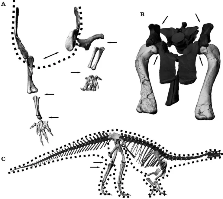
Fig. 5. Range of motion of the fore limb of prosauropod Plateosaurus engelhardti Meyer, 1837 using the digital skeleton mount of GPIT1, from Trossingen, Germany. A–E. Left scapula and fore limb in anterior (A), anterolateral (B), anteromedial (C), lateral (D), and dorsal (E) views. Equal colors are identical positions. B is parallel, C is perpendicular to the main axis (flexion/extension) of the glenoid. Length of humerus 350 mm. Dashed line(s) refer to: body midline (A), orthogonal to scapula blade long axis (B), body midline and main axis of glenoid (C). Red numbers in B refer to elbow, black to humerus flexion/extension. Numbers in C refer to humerus abduction/adduction versus the vertical. F. Left radius and ulna in articulation in (top row) proximo− lateral, medial view, (bottom row) distal and lateral views. Length of ulna 237 mm. G. Radius and ulna in proximal view. Dotted line indicates main joint axis of elbow. Circle and lines show method for determination of theoretical maximal pronation angle. H–M. Left manus. H, I. Left to right: flexion, neutral position and extension in dorsal (H) and palmar (I) views. Digit IV duplicated in neutral position views to show lateromedial deviation range. J–M. Oblique views of flexion (J, K) and extension (L, M). Length of metacarpal III 97 mm.
manual manipulation of specimens and digital manipulation of 3D data from several individuals (e.g., GPIT1, GPIT2, MB.R.4402, MB.R.4404), the results of Bonnan and Senter (2007), who studied AMNH 2409 exclusively. Bonnan and Senter (2007) also show conclusively that alternative methods for manus pronation, e.g., proximo−distal motions of the ra− dius, are not possible in plateosaurid dinosaurs. Additionally, as pointed out by Mallison (2010), the posture of articulated skeletons in the field argues against Plateosaurus being capa− ble of turning the palm ventrally without massive humerus ab− duction.
Forelimb: carpus, metacarpus and digits.—The block− like structure of the wrist appears to block rotating motions (see also Bonnan and Senter 2007), but to allow significant extension and flexion. The digits flex strongly, with the claws of digits II and III potentially able to touch the palm. In contrast to the description by Huene (1926), the digits are not widely splayed and the metacarpus does not show a signifi− cant transverse curvature. Only the whole of metacarpal V and the distal end of metacarpal 4 are placed clearly palmar in relation to the others (see also Jaekel 1913–14: fig. 20). This is a marked contrast to the tubular manus of sauropods (Bonnan 2003). The distal articular facet of metacarpal IV, however, is slightly tilted against those of metacarpals II and III. This directs the digits slightly medially during flexion. Digit III and especially digit IV also have some lateral mobil− ity between the metacarpal and the basal phalanx, allowing lateral deviation and therefore some countering action of the flexed digit against digits I and II (Fig. 5G–J). The angle is quite limited at ~25°, comparable to the lateral mobility pres− ent in the digit IV of humans. Fully flexed, the digits can grasp around objects, and digit V opposes digits II and III (Fig. 5G–J, Mallison 2010: fig. 6). Digit I, as has also been pointed out for the closely related Anchisaurus by Galton (1976), is not angled strongly against digit II (Fig. 5G–K; Mallison 2010: fig. 6; contra Galton 1971a, b), and flexion reduces the angle to only 13° compared to the long axis of metacarpal III (Galton 1971a, b).
The right manus of SMNS F 33 is preserved in articulation, as is SMNS 13200 k, a right manus assigned to Pachysaurus by Huene (1932), a genus regarded as a junior synonym of
Plateosaurus by Galton (1985). These two hands are the sole
articulated prosauropod manus from the German Keuper pre− served without significant transverse compression and whose elements have not been separated during preparation. In both, metacarpals II through IV are articulated with their shafts nearly parallel, forming an angle of less than 20°, and the en− tire metacarpus has no transverse arching. The visible parts of the bones do not suggest that this is a taphonomic artifact, con− firming the results obtained for GPIT2.
The manus appears to allow significant digit extension (Fig. 5G, H, K, L). The distal condyles of the metacarpals are smoothly rounded trochleae, and there are small and shallow hyperextension pits visible on the distal ends of metacarpals II through IV. The phalanges show only very shallow or no
hyperextension pits. Although the manus could certainly by used to support part of the animals weight, it does not show any special adaptations for a significant role in locomotion beyond the strong hyperextension of the digits. For example, the metacarpus is not elongated, and shows a significantly lesser development of inter−element contact surfaces, and thus stability, than the pes.
Hindlimb: hip.—Both hindlimbs of GPIT1 are preserved al− most completely. The left pes lacks the distal tarsals and the ungual of digit IV, while the right hindlimb has large plaster replacements on the metatarsus as well as the phalanges. Therefore, a copy of the left tarsals, metatarsus and toes was used instead of the original right side elements. Most bones do not show any indications of significant deformations, ex− cept for the left fibula. This bone is damaged slightly below midshaft, and the remaining parts have been glued together in a slightly bent position. Overall, the left fibula is 1.7 cm shorter than the contralateral element. In the virtual skeletal mount it was positioned with the distal end correctly articu− lated with the tibia and the tarsals, therefore the proximal end is shifted distally compared to the tibia.
In the parasagittal plane, the femur can cover an angle of 65° without abduction (Fig. 6B), if retraction is assumed to end at the level of the ischia, and protraction before collision with the pubes. Further retraction may well have been possi− ble, depending on the exact architecture of the m. caudo− femoralis longus. However, resting positions are only feasi− ble if the femora can be protracted at least 15° beyond the pubes (Fig. 6A, C, see below).
These limits on motion of the hindlimb in the parasagittal plane indicate that the long axis of the sacrum must have been held in a roughly horizontal position for speedy locomotion, as already concluded by Christian et al. (1996) and Christian and Preuschoft (1996). In a steep position as suggested for Anchi−
saurus by Marsh (1893a, b) and for Plateosaurus by Jaekel
(1913–1914) and Huene (1907–1908, 1926), hardly any room is left for femur motions in the parasagittal plane, because the ischia approach a near−vertical position.
Adduction and abduction limits are difficult to determine. Bringing the foot under the body midline requires 15° of adduction, measured from the vertical (Fig. 6C), and abduc− tion angles of as much as 45° may have been possible. Clear− ing the pubes at large protraction angles requires at least 22° of abduction (Fig. 6C). However, the missing cartilage in the hip joint does not allow an accurate assessment.
Hindlimb: knee.—The knee of Plateosaurus appears to be a simple hinge joint at first approximation, as in all extant taxa with parasagittal limbs. The exact degree of inversion and eversion possible cannot be determined due to the lack of preserved articular cartilage. The preserved bone shape of the distal femur end does not form a smooth continuous cur− vature in lateral aspect. Rather, there is a marked flattened part of the articular end, at a 110° angle to the long axis of the femur shaft. Assuming that this shape corresponds closely to the shape of the actual articular surface leads to the conclu−
Fig. 6. Range of motion of the hind limb of prosauropod Plateosaurus engelhardti Meyer, 1837 using the digital skeleton mount of GPIT1, from Trossingen, Germany. A–H. Left pes in left to right: flexion, probable standing pose, extension, in lateral (A), medial (B), oblique (C–F), plantar (G), and dorsal (H) views. Length of metatarsal III 231 mm. I–K. Pelvis and left hind limb, in lateral (I, J) and anterior (K) views. I, K, probable standing (blue) and minimally possible flexion (resting) pose; J, maximum femur protraction and retraction angles for locomotion, resulting stride length 1.34 m. L. Left hind limb showing knee range of motion. Crus positions left to right: maximal extension, maximum flexion under large loads, maximum flexion for resting. M. Crus in lateral view, showing maximum ankle flexion and extension under load. Length of fibula 463 mm.