HAL Id: hal-01128977
https://hal.archives-ouvertes.fr/hal-01128977
Submitted on 10 Mar 2015HAL is a multi-disciplinary open access archive for the deposit and dissemination of sci-entific research documents, whether they are pub-lished or not. The documents may come from teaching and research institutions in France or abroad, or from public or private research centers.
L’archive ouverte pluridisciplinaire HAL, est destinée au dépôt et à la diffusion de documents scientifiques de niveau recherche, publiés ou non, émanant des établissements d’enseignement et de recherche français ou étrangers, des laboratoires publics ou privés.
Strain-induced inverse magnetostriction measured on a
single contacted Ni nanowire in a polymer matrix
Strain-induced inverse magnetostriction measured on a
single contacted Ni nanowire in a polymer matrix
Do-Ch Pham, Nicolas Biziere, G Melilli, R Pajon, D Lacour, L Bouvot, M
Tabellout, D Lairez, H-J Drouhin, M-C Clochard, et al.
To cite this version:
Do-Ch Pham, Nicolas Biziere, G Melilli, R Pajon, D Lacour, et al.. Strain-induced inverse magne-tostriction measured on a single contacted Ni nanowire in a polymer matrix Strain-induced inverse magnetostriction measured on a single contacted Ni nanowire in a polymer matrix. Materials Research Express, IOP Publishing Ltd, 2014, pp.045017. �10.1088/2053-1591/1/4/045017�. �hal-01128977�
1
Strain-induced inverse magnetostriction measured on single-contacted
Ni nanowire in a polymer matrix
Do-Ch. Pham,1 N. Bizière, 2 G. Melilli, 1 R. Pajon, 1 D. Lacour, 3 L. Bouvot, 3 M. Tabellout, 4 D. Lairez, 5 H-J. Drouhin1, M.-C. Clochard, 1* J.-E. Wegrowe1*
1. LSI, CEA/CNRS/Ecole Polytechnique, Ecole Polytechnique, 91128 Palaiseau Cedex, France
2. CEMES, CNRS and Toulouse University, 29 Rue Jeanne Marvig, 31055 Toulouse, France
3. IJL, UMR CNRS 7198, Université de Lorraine, 5406 Vandoeuvre les Nancy, France
4. Institut des molécules et des matériaux du Mans CNRS 6283, Université du Maine, 72085 Le Mans, France
5. LLB, CEA-Saclay, 91191 Gif-sur-Yvette Cedex, France
* corresponding authors : Marie-claude Clochard, +33 1 69 33 45 26 e-mail : clochard@cea.fr; Jean-Eric Wegrowe, + 33 1 69 45 55, e-mail : jean-eric.wegrowe@polytechnique.edu
Keywords: ion track membranes; magnetoresistance; magnetostriction; magnetic nanowire
ABSTRACT
The effects of thermoelastic and piezoelectric strain of an active polymer matrix on a Ni nanowire are studied at the nanoscale by measuring the inverse magnetostriction of single-contacted Ni nanowires. The reorientation of the magnetization is measured by anisotropic magnetoresitance. In the absence of strain, the Ni nanowire shows a typical uniform rotation of the magnetization as a function of the external field. In the case of piezoelectric or thermoelelastic strain occurring in the polymer matrix, the hysteresis loop is strongly modified due to the inverse magnetostriction of Ni. It is shown that the ferromagnetic nanowire plays then the role of a mechanical probe that allows the effects of the mechanical strain to be characterized and described qualitatively and quantitatively. Moreover the stress exerted by the polycarbonate matrix on the nanowire is found to be isotropic while the one produced by the PVDF matrix is anisotropic.
2
Introduction
The physical properties of nanostructured composites are the object of intense investigations for the fabrication of smart materials, nano-sensors and other electronic devices. [1-5] In this context, magnetic materials are especially interesting not only for their response to a magnetic field, but also for their sensibility to mechanical forces. In particular, the possibility of controlling the magnetization with piezoelectric means (especially through the so called inverse magnetostriction effect) is a promising technique for data storage and data processing applications [6-10]. On the other hand, the nanotechnology approach based ion-track shaping of polymer templates has proven to be very efficient for investigating the physical properties of magnetic nanostructures [11-17]. A systematic study of the physical properties of single-contacted magnetic nanowires embedded in an active thermoelastic and piezoelectric polymer matrix is reported. It is shown that a nanowire (NW) embedded in a matrix plays the role of a nanoscopic probe, which is sensitive to the amplitude and the direction of the mechanical stress.
Since the first magnetic measurements performed on arrays of magnetic NWs embedded in a polycarbonate matrix, a significant change of the magnetization at saturation Ms has been observed as a function of temperature, well below the Curie temperature [18]. Such a phenomenon was attributed to the thermal expansion of the matrix inducing a significant pressure on the NW [19-22]. As magnetostrictive properties are inherent to nickel (Ni) materials, a mechanical stress on Ni crystallites provokes a change of the magnetization states (inverse magnetostriction effect) leading eventually to a change of the magnetization M. The amplitude of this effect was however about ten times larger than expected, and further experiments are necessary in order to disentangle the role played by the matrix from that played by the NWs. Note that all these measurements were performed at the macroscopic scales, in a matrix composed of about 105 NWs. The aim of the present work is to better understand the magnetostriction very locally analysing the magnetic properties of a single Ni NW under mechanical stress.
The study presented in this report is performed on single contacted Ni NWs that are grown by electrodeposition in a track-etched piezoelectric (PVDF) and non-piezoelectric (amorphous
3 polycarbonate: PC) polymer membrane used as a matrix. The track-etched PC and PVDF matrices are high density nanoporous membranes (109 pores.cm-2) with a diameter of the NW of about 70 nm (fig. 1).
The anisotropic magnetoresistance (AMR) properties of single contacted NWs are exploited in order to measure the magnetization states as a function of i) the amplitude and angle of the applied magnetic field, and ii) the mechanical stress actuated by the matrix. Technical details mainly related to the device fabrication are presented in the Materials and methods’ section. The analysis of the magnetization states and the experimental protocol is presented in Section
I. In Section II, the determination of the reference states without mechanical stress of the
magnetization is performed. The thermo-elastic properties of the PC and PVDF matrices are then studied in Section III, and the response of the magnetization to the thermo-elastic excitation is investigated in Section IV. For the measurements of the response to the piezoelectric stress, an interdigitated mask has been especially designed to separate zones of NW contact for AMR measurements (sub-micron scales) and zones where voltage is applied to the PVDF matrix (tens of microns). The piezoelectric properties of the track-etched PVDF matrix are studied in Section V, while the response of the magnetization to the piezoelectric excitation is investigated in Section VI. The conclusion of this work is that a single Ni NW can be used as a probe in order to measure the amplitude and direction of a mechanical stress exerted at the nano-scale.
Materials and methods
Materials: Bi-stretched and polarized PVDF films were purchased from two different
providers: http:www.acoustics.co.uk/home and PIEZOTECH SA (Thickness: h = 9 µm. Sound velocity: cL = 2250 m/s). Potassium hydroxide, potassium permanganate, potassium disulfite, nickel sulphate and boric acid were purchased from Sigma-Aldrich.
Irradiation: Polymer films were used without pre-treatment. Swift heavy ion (SHI)
irradiations were performed at GANIL, Caen. Films were irradiated with Kr36+ ions (10.37 Mev/amu, fluence 109 cm−2) under He atmosphere. Samples were stored at -20°C under N2 atmosphere until chemical etching.
4
Chemical etching: Track-etched membranes were fabricated from chemical attack (KOH
10N; KMnO4 0.25N; 65°C; 30min) of SHI irradiations of purchased poled PVDF films. Obtained membranes were washed in potassium disulfite solution (15%), then, washed 3 times with deionized water.
Lithography: The lithographic protocol to transfer the mask pattern on the PVDF track-etched
membrane has consisted in several steps. A thick layer of gold 500 nm was first deposited by sputtering on one surface of the membrane. The positive optical resin 18-13 was spread by spin coating on the gold layer (35 s at 5000 rpm followed by 10 s at 6000 rpm) and dried at 70°C during 1.5 min on heating plate. UV insolation through the mask stood for 10 s. The mask pattern was revealed by engraving the insolated resin after contact with the MF 319 developer solution (35 s). Membranes were washed by deionized water and dried under compressed air. The pattern was thus transferred to the gold layer by immersing the membrane during 30 s in a KI bath. Membranes were washed by deionized water and dried under compressed air. The residual resin is then washed by ketone solvent.
Electrodeposition: A piece of track-etched membrane, for which one side has been gold
patterned through a mask by lithography and the other side has been sputtered with 10 nm gold layer to not block the nanopores, is immersed into an aqueous electrolytic solution composed of NiSO4 and H3BO4 (pH =6.2). The electric potential between the thicker golden surface of the track-etched membrane (working electrode) and an Ag/AgCl reference electrode is set to -1 V. Electrodeposition time is defined by the current intensity increase when a single Ni NW contacts both golden sides of the membrane. The final wires obtained are ultra thin cylinders of typically 10000 nm length and 70 nm in diameter.
Dilatometry measurement: The NETZSCH TMA 402 Hyperion® was equipped with a steel furnace capable of operation between -150 and 1000°C. Measurements were performed in tension. Data acquisition and evaluation, as well as instrument control, were accomplished with a MS®-WindowsTM Thermal Analysis software package. Sample holder: SiO2; sample thermocouple: type K; Pushrod force: 0.05N; temperature program: -50 to 100°C at 3K/min; Atmosphere: He at 40ml/min; Calibration standard: Pt; Sample length: 10mm.
5
Dielectric measurements. They were performed over the frequency range 1 MHz to 1GHz
using the Novocontrol Broadband dielectric spectrometer based on an HP4291A radio frequency impedance analyser coupled with a precision coaxial line. The sample cell consists on two round golden plates electrodes filled with the material to form a termination capacitor of the golden coaxial line.
Magnetoresistance measurements: Electrodeposited NW embedded in a gold sputtered PC
membrane is permanently bonded on a homemade sample holder comprising connections for current injection and voltage measurement. Sample holders are equipped with a little cupper coil for external temperature measurements.
The current injection is insured by a Keithley 224 Programmable DC current source (accuracy ± 0.05%). The voltage difference between the NW ends is measured by a Keithley 182 Sensitive Digital Voltmeter having an intrinsic noise of ± 20nV for a source resistance of 1k. To avoid electromagnetic noises artefacts, the analysed sample is surrounded by a Faraday cage. The sample holder is placed in a 1.2T bipolar electromagnet provided by Bouhnik supplied with a ± 50A generator.
I. Magnetic characterization based on anisotropic magnetoresistance (AMR) properties
Thanks to the magnetoresistance properties, it is possible to access to the magnetization states of a nano-magnet via voltage measurements, with unprecedented sensitivity [12-19]. The relation that links the resistance to the magnetization vector M is given by the formula R(M) = Rmin + R cos2[ (M)] where is the angle between the magnetization M and the direction of the electric current density J, R is the maximum resistance variation due to AMR and Rmin is the minimum resistance, that corresponds to the magnetization perpendicular to wire axis [20,21]. Due to the high aspect ratio in the nanowires (7/1000), the electric current density J inside the metal is constant and homogeneous along the wire axis in the direction J = J0 ez where J0 is constant (galvanostatic mode).
On the other hand, the nanoscopic size of the sample leads to a uniform magnetization:
M = Ms er where Ms is the saturation magnetization of Ni and er is a radial unit vector [11].
6 wire axis Mz = Ms cos(and the simple quadratic relation R(M) = Rmin + R (Mz/Ms)2 links the resistance and the magnetization states. Furthermore, in the following study, the Ni NW is composed of randomly oriented nanocrystallites of about 10nm, so that the magnetocrystalline anisotropy is averaged to zero. The anisotropy is only due to the shape anisotropy (i.e., it is due to the so-called “demagnetizing field”, or dipolar field). The corresponding energy is Ed = - Hd.Mwhere the shape anisotropy field is defined with the help of the anisotropy tensor N by Hd = -N M. In the case of quasi-infinite cylinders (high aspect ratio), the shape anisotropy field for the Ni NWs is oriented along the wire axis Hd=Hd ez and N=2Ms. We have Hd ≈3kOe.
A - Let us first ignore the inverse magnetostriction effect (i.e., the mechanical stress exerted
by the matrix on the NW is neglected in a first approach). The magnetization states are then defined by the external field and by the shape anisotropy only. In that case, the energy is defined by the two corresponding terms, the Zeeman coupling EZ = - M.H and the shape anisotropy energy Ed = - M.Hd.
E0( = -HMs cos(H) - Hd Ms cos2 (1)
where H is the angle between the applied field and the NW axis. The quasi-static states of the magnetization are defined by the minima of E0(. Due to the cylindrical symmetry, all planes defined by both the wire axis ez and the external fields H are equivalent (the configuration space is reduced to the single variable . The quasi-static states of the magnetization are given by dE0/d = 0 and d2E0/d2 ≤ 0 (see reference [11] for detailed analysis). Note that the physical signification of this quasi-static condition is that the magnetization has to find the position in its configuration space, such that the effective field vanishes: Heff = - grad E0 = H
+ Hd = 0 (where the operator gradient is defined on the magnetic configuration space). This
condition is equivalently verified by two sets of parameters {H,}1 and {H,}2, that defines the two branches of the hysteresis loop. The irreversible jump that occurs between the two branches of the hysteresis is defined by independent conditions (this is the nucleation problem: e.g., d2E0/d2 = 0 in the case of the Stoner-Wohlfarth model). This out-of equilibrium problem is however not considered in the present study.
B- If the inverse magnetostriction effect comes into play, the cylindrical symmetry is broken
in the general case. The magnetization M should now be described by the coordinates () and the external field by the coordinates (HH). The Zeemann coupling reads now:
7 Ez = - HMs (sinH cos H sin cos + sinHsinH sin sin + cosH cos). (2)
Nanowire = z axis H X axis M y axis s ms Hms a
Figure 1. Left: TEM image of a ultra-cryomicrotomy cut of a contacted electrodeposited Ni NW in a PVDF track-etched membrane. Ni NW diameter is 70nm. Right: Scheme of magnetization and stress forces s applied to the magnetic NW, with the definition of the angles.
On the other hand, the contribution of the inverse magnetostriction to the energy is given by [23, 24]:
Ems ≈ 3sssin2a (3)
where s is the saturation magnetostriction coefficient, s is the stress and a is the angle between the magnetization and the stress direction. The magnetostriction field Hms can be defined by the relation Hms= Ems/Ms and Hms is defined by the amplitude Hms and the coordinates (ms,ms). The angle avaries with the position of the magnetization (see Figure 1). Since we have M.Hms = cosa, the angle a is expressed by the relation:
a = Arcos{sinms cos ms sin cos + sinmssinms sin sin + cosms cos}. (4) Note that if we assume =ms=0, a= ms- (the latter point anticipating further discussion in section IV).
The total energy is now the sum Et()= Ez()+ Ed()+ Esm(). The quasi-static states of the magnetization are calculated numerically with finding the minimum of the function Et() for different values of the parameters {H, HH This condition corresponds to the summation Heff = - grad Et = H + Hd + Hms= 0
8 Accordingly, the experimental protocol used in order to determine the direction and amplitude of the mechanical stress consists in rotating the sample in order to find the condition
Hms3ssMs) sin2(ms-
II. Reference AMR states
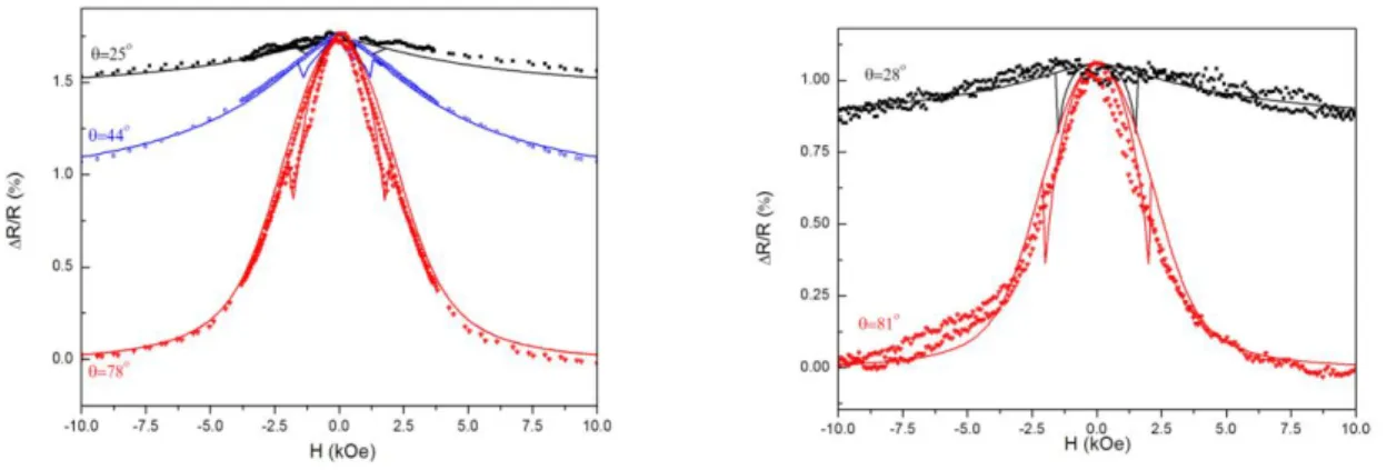
Figure 2 shows the magnetoresistance hysteresis loop for PC (Fig. 2a) and PVDF (Fig. 2b) matrices at room temperature and without piezoelectric excitation (reference conditions). The change in the amplitude of R/Rmin between PC and PVDF is due to the resistance of the electric contact on the bottom of the matrix (this variation is observed from one sample to the other and is not related to the nature of the matrix) [25].
Fig.2. Magnetic field dependence of the magnetoresistance at various angle of the applied field. Measurements (dots) and Fit (lines). (left) Ni NW in polycarbonate matrix, and (right) Ni NW in piezoelectric PVDF matrix. The two profiles are identical with anisotropy field Hd = 3kOe.
The continuous lines correspond to the ensemble of minima dE0/dH = 0 calculated from Eq. (1), for various values of the parameters (H,H). The shape anisotropy field is fixed at Hd = 3kOe. A first fit is performed at fixed angle H in order to obtain R/Rmin, and to confirm the value of Hd. The other curves are then calculated without adjustable parameters. Accordingly, Fig. 2 shows that Eq. (1) is valid: the magnetization is indeed uniform for all quasi-static states and the anisotropy is uniaxial and oriented along the wire axis. All other possible contributions to the energy can be ignored. This does not mean the absence of mechanical contributions at room temperature, but these contributions cannot be distinguished from the other parameters in Eq. (1). Note that the irreversible jump from one branch of the hysteresis to the other branch can be observed in Fig. 2. In the following, we will however focus on the
9 reversible part of the hysteresis only, i.e., on the envelope of the curve R/R(H). The characterisation shown in Fig. 2 constitutes our reference curve for Ems= 0.
III. Thermo-mechanical effects: comparison between PC and PVDF matrices
In order to compare the dilation effect of PC and PVDF polymers, the thermal expansion and the coefficient of thermal expansion (Tref 290K) of each polymer films of same thickness have been measured independently.
The piezoelectric thermal expansion of the PVDF film is depicted in Fig. 3. The sample expands continuously up to the maximum sample length which was detected at 75°C with an expansion of 0.5%. Further, the sample length decreases till the end of the measurement. The same sample is heated a second time. During the second run, the sample expands continuously over the entire measurement range. A second sample of the PVDF film is measured. The results are very similar. The peak at 75°C is due to the crystal structure that changes from to a phase when the polarized PVDF loses its piezoelectric behavior.
-0,50 0,00 0,50 1,00 220 240 260 280 300 320 340 360 380 1srt heating PVDF film 2nd heating PVDF film 1srt heating PC film 2nd heating PC film
L/L
%
Temperature KFigure 3. Thermal expansion coefficient as a function of the temperature with two heating runs for piezoelectric -PVDF film (black curves) and for PC films (grey curves).
10 The thermal coefficients at reference temperature of 20°C for PVDF and PC are found equal to 9.99 10-5 K-1 and 9.45 10-6 K-1 respectively. That means one order of magnitude difference between the two polymer bulks. One could thus expect a more dramatic effect of membrane dilation with -PVDF on the magnetoresistance measurement of embedded magnetic NWs than PC.
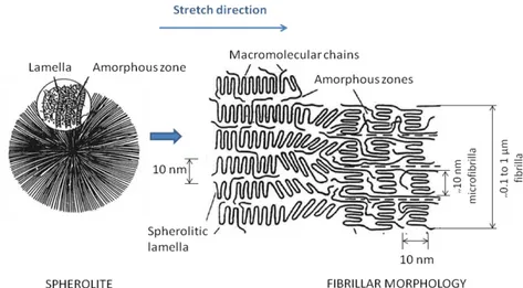
The chosen -PVDF for this study is a semi-crystalline polymer (crystallinity rate around 40%). To confer piezoelectric property, a-PVDF thin films have been stretched twice in the x and y directions (surface plane). Under stretching, the initial spherolites, initially present in a -phase and made of successive layers of crystalline lamella and amorphous zones (Fig. 4), change into ellipsoids, then are destroyed and macromolecular chains re-crystallize in phase. The stretching alternatively creates amorphous and crystalline zones leading to fibrillar morphology.
Figure 4 : Schematic presentation of fibrilla and microfibrilla alignment induced by stretching in one direction
The crystallites are oriented normally to the initial film surface (xy). The PVDF polymer chains in -phase adopt a trans-trans (TT) conformation known as zig-zag planar conformation leading to an orthorombic lattice formation where all the fluorine atoms are located in one side of the polymer backbone. Piezoelectricity can then be obtained by orienting the molecular dipoles of polar -PVDF in the same direction by subjecting appropriate films to an intense electric field: this is polarization. This polarization is mainly attributable to the spatial arrangement of the segments of the macromolecular chains, and the
11 contribution of the injected charges to the piezoelectric effect is of secondary importance. The polarized electrets are thermodynamically stable up to about 90°C.
Anisotropic materials like semi-crystalline bi-stretched -PVDF possess properties which are dependent on the direction in the material. Stress and strain are correlated the stress-strain tensor is given by s(x,y,z) = E(x,y,z) × (x,y,z) where s is the stress, E is the Young’s modulus and the strain. The figure 5 displays the spheroid shapes drawn by PC and -PVDF
stress fields. sz sx sy sx=sy x y z
2D view = Film surface plane 3D view sx sy x y z sz sx=sy= sz
Figure 5. Left: Scheme of the sphere shape describing the stress field in isotropic PC; right: scheme of oblade spheroid shape of -PVDF stress sPVDF occurring in the polymer film during thermal
expansion.
The elastic modulii in z direction and xy plane, Ez and Exy respectively, represent the stress direction with respect to the z axis. For PC, Ez equals to Exy (2.3 GPa). For PVDF, a value of 5.8 GPa was measured for Ez by ultrasonic technique and the value of 1.6-2.2 GPa was obtained for Exy from traction experiment.
12
IV. Response of the magnetization to thermo-mechanical stress
Dubois et al. have measured by XRD the change of the lattice parameters for Ni crystallites inside the NWs embedded in a PC matrix under stress due to temperature variation [20]. The change of the lattice parameters provokes in turn a change of the magnetization states due to the contribution of the magnetostriction energy.
In our experimental protocol, the magnetostriction is deduced from the change of the magnetization states with respect to the reference state described in Section II. The thermo-mechanical origin of the observed variation is checked by measuring the heating effect following two sources of heat: i) the heat is produced by a constant coil heater glued to the membrane (the maximum power injected is of the order of one Watt) and ii) the heat is produced by Joule effect by injecting a current of the order of 1 mA inside the NW (the maximum power is of the order of 0.1 Watt). In both cases, the temperature is brought to the measured NW’s resistance.
In the case ii), the heating is confined inside the NW and in the metallic contacts and electric wires, and we do not observe significant variations of the AMR profile in the temperature range investigated (maximum variations of T ≈10K). In contrast, the variation observed in i) when heating the matrix only - using the coil heater - is dramatic. The comparison guarantees that the variation observed is uniquely due to the thermal expansion of the matrix, and not from other variations due to the temperature.
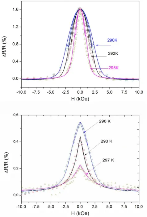
Fig 6 shows that the effect of the thermo-elasticity is twofold. Firstly, it plays on the anisotropy (the width of the R/R(H) curve), and secondly, it plays on the amplitude of the AMR signal. It can indeed be observed that the maximum of the R/R(H) curve is not reached: this means that the magnetization does no longer align along the wires axis (maximum AMR) at any external field applied in the plane of the matrix. The variation on the anisotropy can be observed for both PC (Fig. 6a) and PVDF (Fig. 6b) matrices. The variations are of the order of 50% of the anisotropy field. This variation is attributed to the thermo-elastic stress exerted by the matrix on the NW, and the corresponding magnetostrictive response of the Ni NW. Indeed, no effect is observed with NiFe NWs, for which the magnetostriction is known to be negligible [19-22]. Three curves are plotted in Fig. 6a: at
13 room temperature (290K), at 292K, and at 295K, and then back to room temperature in order to check that the effect is only due to the elastic deformation.
Figure 6: Anisotropic magnetoresistance (AMR) of Ni NW as a function of the magnetic field (at 90°), for different temperature. For convenience, the resistance has been corrected by the thermal variation
R(T) = R(290K)-R(T). (top) Ni NW in PC matrix and (down) Ni NW in -PVDF matrix. Line curves are calculated from the energy equation (1) adding a supplementary term of magnetostriction (equation 3).
The comparison between the two matrices shows that the variations are not similar using PC or PVDF track-etched matrix to embed the magnetic NW. In the first case, the variation is
14 only due to a reduction of the anisotropy – i.e., the width of the curve -. While in the case of PVDF, both the amplitude and the width are affected. This observation can be firstly attributed to the difference of the thermal expansion coefficients between the two polymers. A key of understanding is the tremendous variation of the amplitude of the AMR in the case of PVDF. It means that the magnetization can no longer be aligned along the wire axis and keeps a non-zero angle at zero external magnetic field. It should correspond to a supplementary field contribution out of the plane defined by the wire axis and the external field that breaks to cylindrical symmetry (the contribution is out of the plane . This contribution is attributed to a magnetostriction induced by the thermo-elastic stress. This hypothesis is verified with calculation of the minima of the total energy, including the magnetostriction contribution Eq. 3. The results are summarized in Fig. 7.
Figure 7. Experimental data and calculated curves of Anisotropic MagnetoResistance (AMR) of Ni NW embedded in a-PVDF matrix as a function of the magnetic field for different temperatures and fitted curves. RH0 and H are fixed at 0.6 and 80° respectively from reference curve on the same
sample at room temperature (290K). ms is not taken into account as the set-up does not vary around
15 Curve fitted parameters are summarized in the table of Fig. 8. A privileged angle ms was found equal to 72°±3 from the Ni NW axis. The amplitude of the inverse magnetostriction Hms varies linearly with the temperature, as expected according to the linear variation observed in Fig. 3 for the thermal expansion coefficient of -PVDF and PC.
0 0,1 0,2 0,3 0,4 288 290 292 294 296 298 H ms (T) T (°K)
Figure 8: Inverse magnetostrictive field induced by the external stress on the Ni NW as a function of the temperature. The linear fit gives a slope of about 0.05 T/K. Data in the table represents AMR curve fitted paramaters at various temperatures. The anisotropic field Hms is deduced from the Eq.5.
In order to complete the characterization of the thermo-mechanical stress effect on the Ni NW magnetostriction in -PVDF, the AMR measurements have been performed keeping the magnetic field angle to the NW axis fixed and changing the angle a (rotation around the wire axis). The results are summarized in figure 9. The angle between H and Hms is imposed by the stress orientation. [26] The magnetostrictive field Hms interaction with the external magnetic field H is responsible for the disappearance of the AMR signal for a variation of the order of T ≈ 10 K. No significative contribution of a has been pointed out confirming the oblate spheroid model for the tensile strength of PVDF around the Ni nanowire keeping the NW axis as the symmetry axis.
External Heat (K) ms Hms (T) 291 74° 0.05 292 74° 0.15 293 73° 0.20 295 75° 0.25 297 70° 0.38
16 Figure 9. Table summarizes fitted results of the experimental data of AMR of Ni NW embedded in a -PVDF matrix as a function of the magnetic field (at H = 78°) for temperatures variation T=5K.
RH0 is fixed at 0.33±0.03 from reference curve on the same sample at room temperature (290K), H equal to 0 (reference angle). The magnetostriction angle ms has been found equal to 72.5±2.5°
and inverse magnetostriction field Hms is deduced from the Eq. 5. The scheme on the left offers a better
understanding of vectors’ orientation.
The PVDF stress field sPVDF can be expressed from linear elastic theory as s E (Hooke’s law) whereis the -PVDF Young modulus (EPVDF=2-6 GPa) and the strain which is here the thermal expansion deformation. From Fig. 3, the thermal expansion coefficient of the chosen -PVDF membrane is given by the slope and found equal to 10-4 K-1 resulting in sPVDF /= 2-6.105 Pa.K-1. The magnetostrictive field, done by Eq. 5, can be reduced to: T M T H Ni s s ms s 2 3 (6) a ms Hms (T) 0 75° 0.17 15° 70° 0.13 73° 70° 0.19 80° 70° 0.16
17 Wheres is the magnetostriction coefficient (s ≈ -3 10-5 for Ni) and Ms is the saturation magnetization of the Ni (Ms = 485 emu.cm-3= 485.103 J.T-1.m-3).
From Fig. 9, 0.05 . 1 K T T Hms 1 8 1 10 . 10 . 5 . 05 . 0 10 K Pa T K T T T Hms
s
Nis
NiIt means that the induced stress field in the Ni NW per Kelvin is 1000 time higher than the
initial stress field provoked by the PVDF thermal expansion. Elasticity theory, which is a
continuum theory that necessarily averages over macroscopic regions, has been found
applicable for the calculation of the lattice strain in structures with nanoscopic dimensions.
[27, 28] Consequently, we suppose continuous lattice displacement at the interfaces. The
increase of stress in the interface metal-polymer should mainly due to Young’s modulii
difference.
The tensile strength in Ni is 230 GPa meaning two orders of magnitude in comparison to
PVDF or PC. The resulting strain variation per Kelvin of a Ni NW is roughly 20.10-4 K-1. In
comparison to research work on electromechanical stress applied to an array of Ni NWs in a
PVDF matrix [22, 29], the strain is found here higher by a factor 5-10.
Two assumptions can be proposed. Firstly, the stress concentration effect should not be
considered using linear elastic theory but should be expressed as anisotropic non-linear
stress-strain law. [30] Secondly, only very few contacted NWs are measured and, in that particular
case, the magnetoelactic anisotropy energy becomes very high [29] enhancing the resulting
stress.
The physical reason for that is that the elastic modulus of a nano-object is greatly enhanced in comparison to the bulk when the size becomes very small. From ref. [31], this enhancement of Young’s modulus is attributed to the surface tension sS:
18 where is the Poisson’s coefficient, E the Young’s modulus of the bulk (real), L the length of the NW and D the diameter of the NW. The surface tension sS varies as function of the temperature [32] as follows:
ss(T) = sL + sT ( T - TL ) (8)
where sL is the surface tension of the material at liquid temperature TL and sTthe thermal
coefficient of the surface tension.
Taking into account a TL of 1454 K, sLof 1.77 and sTof -3.3 10
-4
N.m-1.K-1 , the surface
tension of the Ni NW is evaluated at 2.15 N.m-1 at 293 K from Eq. 8.
Considering longitudinal velocity of ultrasounds in Ni VL= 5640 m.s-1 and bulk density of 8902 kg/m3, the Young’s modulus is averagely of 283 GPa. For a Ni NW of 10 µm length and 75 nm diameter, the apparent elastic modulus calculated from Eq. 7 is evaluated to 748 GPa. The resulting strain variation per Kelvin of Ni NW is then lowered to 6.10-4 K-1.
In order to validate the importancy of magnetostrictive effect in a single Ni NW by a
mechanical pressure, we have also study the same system under electrical bias using
piezoelectric -PVDF membrane.
V) Piezoelectric properties of track-etched -PVDF membranes
However, before we go any further, let us not underestimate the depolarization effect of swift heavy ion bombardment through a PVDF thin film. [33] We have chosen a fluence of 109 ions.cm-2 to avoid being in depolarization conditions. In order to verify if the etching reaction may have also affected the piezoelectric properties of PVDF, piezoelectric constants of polymers (-PVDF and track-etched -PVDF) have been determined using an optical heterodyne interferometer to measure the deformation. The minimum detectable displacement is 10-3 Å and the accuracy is 5%. For PVDF and track-etched PVDF, the method leads to a constant d33 equal to -14 x 10-l2 m/V and -13.6 x 10-l2 m/V respectively.
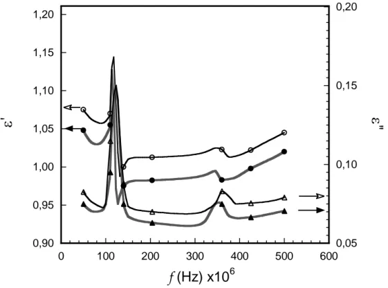
In addition, dielectric measurements have been performed. Fig. 10 shows similar dielectric spectra for non-irradiated and track-etched polarized PVDF membranes. These spectra present resonance peaks at 118 MHz and 120 MHz respectively and the same first odd harmonic at 355 MHz and 360 MHz. The frequency should be compared to the calculated one from: =
19 2h = cL/f where is the wavelength, h the film thickness (9 µm), cL the sound velocity (2250 m.s-1) and f the frequency. Calculated f is equal to 125 MHz. The good agreement with the experimental results (Fig. 10) proves the piezoelectricity of both membranes.
0,90 0,95 1,00 1,05 1,10 1,15 1,20 0,05 0,10 0,15 0,20 0 100 200 300 400 500 600
'
"
f (Hz) x10
6Figure 10: Dielectric spectra of polarized PVDF films (plain symbols) and track-etched membranes (open symbols): real part (’) and imaginary part (”) of dielectric permittivity versus frequency f.
The resulting piezoelectric track-etched -PVDF membrane serves as template for Ni growth by electroplating.
To contact a single Ni NW and to apply the voltage to the piezoelectric nanoporous PVDF membrane without creating short-cuts, different conductive zones have been defined at the micron scale. A mask pattern for lithography has thus been designed with 50 lines in series to grow by electrodeposition and contact the electrodeposited Ni NW. These lines are surrounded by larger ones, namely the capacitances, on which the voltage is applied (Fig. 11). FESEM allows a full characterization of the resulting device.
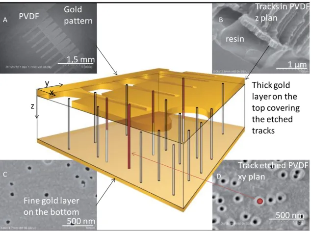
20 A B C D 1 µm 500 nm Gold pattern PVDF
Fine gold layer on the bottom 1,5 mm 500 nm Thick gold layer on the top covering the etched tracks resin Tracks in PVDF z plan Track etched PVDF xy plan z x y
Figure 11: Central scheme illustrating the nanofabrication of the device with a single contacted Ni NW (red) in a track-etched piezoelectric PVDF membrane. FESEM image of A) the gold pattern obtained from lithography with interdigitated lines – fine lines serve herein as electrode during electrodeposition process- ; B) a cryo fracture of the device exhibiting the photoresist resin layer, the cross-section of 200 µm thick gold layer (working electrode thickness) and etched tracks crossing through the PVDF membrane (z plan); C) track-etched PVDF membrane surface covered by a 10 nm thick gold layer used to contact the Ni NW (nanopores are not blocked); D) nude track-etched PVDF membrane - xy plan - (fluence 109 pores/cm2; Rmean= 25nm); the red dot filling a track herein is to
sketch the single contacted NW .
The gap d between lines and capacitances has to be in the range of 10 µm to operate the -PVDF plastic deformation on the NW. Indeed, the plastic deformation decreases exponentially from the capacitances edges to the contacted NW. Larger gaps would lead to insufficient pressure on the NW. The line width (Lcontact) has to be of the same range than membrane thickness (around 10 µm) to minimize the electrostatic field screening the contacts. Once the electrodeposited Ni NW creates an electrical contact between a golden line on one side of the piezoelectric track-etched PVDF membrane and the thin gold layer on the other
21 side, the magnetoresistance of the single contacted NW is measured as a function of the magnetic field to characterize its magnetic configurations at room temperature under voltage (Fig. 12).
VI. Response of the magnetization to piezoelectric effect
The effect of the mechanical strain applied by the plastic deformation of the piezoelectric PVDF membrane on the single Ni NW is shown in Fig.12. The value R/Rmin (the AMR in %) is plotted as a function of the applied magnetic field with and without the application of electric field on the PVDF matrix. Due to the contribution of the resistance of the patterned lines shown in Fig. 11A, the total resistance Rmin is large and the ratio R/Rmin is of the order of 0.25% (instead of 1.5% in Fig. 2).
Fig.12: Comparative measurements with piezoelectric voltage (open circles) and without piezoelectric voltage (full squares). The applied field is perpendicular to wire axis (H = 90°). Continuous curves
are the best fit deduced from the uniform magnetization model with and without the magnetostrictive term. The amplitude of the stress field is found to be about Hms=1 kOe (0.1T), with the orientation ms
22 Due to the small signal to noise ratio, each curve in the Fig. 12 is an average of five hysteresis cycles between –1.6 T to 1.6 T (-10 kOe to 10kOe). The modifications observed on the hysteresis loops are due to the inverse magnetostriction, and they allow a direct observation of the stress field s acting at the nanoscale on the wire.
The magnetoelastic response is investigated further by applying the Stoner-Wohlfarth model on the data with a supplementary magnetostrictive term [11 – 15].
The variation of the amplitude of the AMR signal due to the piezoelectric effect shows that the induced stress field in the Ni NW has the same orientation as in case of thermal expansion of the polymer matrix. The contribution of the magnetostriction is responsible for the variation of the amplitude of the AMR observed in Fig. 12 as it has been established by varying the temperature.
Conclusion
The response of the magnetization to a mechanical strain – i.e. the inverse magnetostriction effect - has been measured on single contacted nanowires embedded in PC and PVDF track-etched matrices. The inverse magnetostriction effect due to the active matrix has been measured through the magneto-transport properties. The magnetization states of the Ni NWs under mechanical stress are deduced from the measurements.
Two kinds of mechanical excitation have been investigated: the thermoplastic stress induced by thermostatic heating of the matrix (on both PC and PVDF) and the piezoelectric stress (PVDF only) induced by the electromechanical properties of the PVDF. In both cases, the amplitude of the effect is important: the magnetic hysteresis loop is modified significantly.
The comparison with the mechanical properties of the matrices measured independently confirms that the single embedded Ni NW plays the role of an efficient magneto-mechanical probe. The magnetoresistance of the NW measured as a function of the mechanical excitations shows that the stress is anisotropic in the case of PVDF matrices, while it remains isotropic for PC matrix. In the last case, the longitudinal to transverse ratio of the elastic modulus is of the order of 1/3, in agreement with the direct measurements on Young modulus performed on the PVDF film.
23 The magnetoelastic stress orientation induced in the Ni NW is thus directly related to the polymer matrix mechanical stress field. The stress concentration effect has been shown in Ni NW and may be attributed to magnetoelastic anisotropy energy increase due to single contacted NWs. Even though a reasonable set of experiments and modeling trials have been collected, there is still room for further finite-element stress-strain calculations to finally draw the complete image of the stress forces at the polymer-Ni interface.
Acknowledgement
The authors want to thank the French government financial support through DGA/REI contract n°2009-34-028 and the RTRA (Triangle de la physique) through project DEFIT n° 2009-075T and DECELER 2011-085T. The authors also acknowledge S. Ceste from the POLYMEDIA centre of the Ecole Polytechnique (France) for artwork participation.
References:
[1] Z. Siwy, L. Trofin, P. Kohli, L.A. Baker, C. Trautmann, C.R. Martin, « Protein biosensors
based on biofunctionalized conical gold nanotubes » Journal of the American Chemical Society
127 (2005) 14, 5000
[2] E. Koukharenko, X. Li, I. Nandhakumar, N. Frety, S. P. Beeby, D. Cox, M. J. Tudor, B. Schiedt, C. Trautmann, A. Bertsch, N. M. White “Towards a nanostructured thermoelectric generator
using ion-track lithography » Journal of Micromechanics and Microengineering 18 (2008) 10,
104015
[3] E. Ferain, R. Legras « Templates for engineered nano-objects for use in microwave,
electronic devices and biomedical sensing application” Nucl. Instr. and Meth. in Phys. Res.
24 [4] Y. Zhang, W.S. Zhao, D. Ravelosona, J.O. Klein, J.V. Kim, C. Chappert, «
Perpendicular-magnetic-anisotropy CoFeB racetrack memory » Journal of Applied Physics 111 (2012) 9,
093925
[5] D. Lis, Y. Caudano, M. Henry, S. Demoustier-Champagne, E. Ferain, F. Cecchet, Francesca
« Selective Plasmonic Platforms Based on Nanopillars to Enhance Vibrational Sum-Frequency Generation Spectroscopy » Advanced Optical Materials 1 (2013) 3, 244
[6] N. Tiercelin,Y. Dusch, A. Klimov, S. Giordano, V. Preobrazhensky, and Philippe Pernod, « Room temperature magnetoelectric memory cell using stress-mediated magnetoelastic
switching in nanostructured multilayer » Applied Physics Letters 99 (2011) 192507
[7] S. Yoichi; N. Takayuki; B. Frederic; et al. « Induction of coherent magnetization switching in a
few atomic layers of FeCo using voltage pulses » Nature Materials 11 (2012) 39
[8] Lei Na; Park S.; Lecoeur Ph., Ravolosona D., C. Chappert, O. Stelmakhovych, and V. Holy.
« Magnetization reversal assisted by the inverse piezoelectric effect in Co-Fe-B/ferroelectric multilayers », Pys. Rev. B 84 (2011) 012404
[9], K. Roy, S. Bandyopadhyay, and J. Atulasimha, « Hybrid spintronics and straintronics : A
magnetictechnology for ultra low energy computing and signal processing » Appl. Phys. Lett. 99
(2011) 063108
[10] A. Brandlmaier, S. Geprägs, M. Weiler, A. Boger, M. Opel, H. Huebl, C. Bihler, M. Brandt, B. Botters, D. Grundler, R. Gross, S. T. B. Groennenwein, “In situ manipulation of magnetic
anisotropy in magnetite thin films”, Phys. Rev. B 77 (2008) 104445
[11] J.-E. Wegrowe, D. Kelly, A. Franck, S. E. Gilbert, and J.-Ph. Ansermet, « Magnetoresistance of Ferromagnetic Nanowires », Phys. Rev. Lett.82 (1999) 3681
25 [12] N. Biziere, Ch. Gatel, R. Lassalle-Balier, M.-C. Clochard, J.-E. Wegrowe, and E. Snoeck,
Imaging the fine structure of a magnetic domain wall in a Ni nano-cylinder, Nanoletters 13,
(2013) 2053
[13] N. Biziere, M.-C. Clochard, Pham Do Chung, J.-E. Wegrowe and M. Viret, «
Magnetoresistance on magnetic nanoconstritions: the role of structural defects », J. Appl. Phys. 113 (2013) 173910
[14] N. Biziere, R. Lassalle Ballier, M.-C. Clochard, M. Viret, T. L. Wade, and J.-E. Wegrowe, « Synthesis and magnetic reversal of bi-conical Ni nanostructures », J. Appl. Phys. 110 (2011) 063906
[15] J.-E. Wegrowe, T. Wade, X. Hoffer, L. Gravier, J.-M. Bonard, and J. Ph. Ansermet,
« Magnetoresistance of nanocontacts with constrained magnetic domain walls » Phys. Rev. B67 (2003) 104418
[16] J.-E. Wegrowe, Q. Anh Nguyen, T. Wade, “Measuring entropy production generated by
spin-transfer » IEEE Trans. Mag. 46 (2010) 866
[17] S.V. Kankanala, N. Triantafyllidis « On finitely strained magnetorheological elastomers » J. Mech. Phys. Solids 52 (2004) 2869.
[18] T.R. McGuire and R.I. Potter, « Anisotropic Magneroresistance in Ferromagnetric 3d alloys » IEEE Trans. Mag. 11 (1975)4, 1018
[19] J. Meier, B. Doudin, and J. Ph. Ansermet, « magnetic properties of nanosized wires » J. Appl.
26 [20] S. Dubois, J. Colin, J. L. Duvail, L. Piraux, « Evidence for strong magnetoelastic effects in Ni
nanowires embedded in polycarbonate membranes » Phys. Rev. B 61 (2000) 21, 14315
[21] J. De La Torre Medina, M. Darques, L. Piraux, « Strong low temperature magnetoelastic effects in template grown Ni nanowires » J. Phys. D: Appl. Phys. 41 (2008) 032008
[22] L. Piraux, G. Hamoir, M.-W. Lee, E. Ferain, A. M. Jonas, I. Huynen, and J. De La Torre Medina : « Template Approach for Novel Magnetic–Ferroelectric Nanocomposites » Applied Physics Express 4 (2011) 115001
[23] M. Vazquez, L. G. Vivas “Magnetization reversal in Co-base nanowire arrays” Phys. Status Solidi B 248 (2011) 10, 2368
[24] J.E. Wegrowe, D. Kelly, Truong T., P. Guittienne, J.P. Ansermet “Magnetization reversal triggered by spin-polarized current in magnetic nanowires” Europhysics Letters 56 (2001) 5, 748
[25] T. L. Wade TL and J.-E. Wegrowe, «Template synthesis of nanomaterials», European Physical Journal - Applied Physics 29 (2005) 1, 3
[26] E.C. Corredor, D. Coffey, M. Ciria, Y. Liu, X. Zhang, Z. Zuo, B. Chen,R-W. Li
“Strain-induced magnetization reorientation in epitaxial Cu/Ni/Cu rings” Phys. Rev. B 88 (2013) 5,
054418
[27] Timoshenko, S. P., and Goodier, J. N., Theory of Elasticity, 3rd ed., McGraw-Hill, New York, 1970
[28] G T Baumbach, D L¨ubbert, M Gailhanou “X-ray structure investigation of lateral surface nanostructures - a full quantitative analysis of non-uniform lattice strain” J. Phys. D: Appl. Phys. 32 (1999) A208
27 [29] L. Piraux, G.Hamoir, A. Encinas, J. De La Torre Medina, F. Abreu Araujo « Influence of the
packing fraction and host matrix on the magnetoelastic anisotropy in Ni nanowire composite arrays » Journal of Applied Physics 114 (2013)123907
[30] H. Neuber “Anisotropic Nonlinear Stress-strain laws and yield conditions” Int. J. Solids Structures 5 (1969) 1299-1310
[31] S. Cuenot, C. Frétigny, S. Demoustier-Champagne, B. Nysten “Surface tension effects on the
mechanical properties of nanomaterials measured by AFM” Physical Review B 69 (2004)
1654101-1654105
[32] J. Brillo, I. Egry “Surface tension of nickel, copper, iron and their binary alloys” Journal of Materials Science 40 (2005) 2213 – 2216
[33] J. Hillenbrand, N. Angert , H.L. Hartnagel, R. Neumann « Depolarization radii of latent
heavy-ion tracks in poly(vinylidene fluoride)” Nuclear Instruments and Methods in Physics Research B