Colloquium: Failure of molecules, bones, and the Earth itself
The MIT Faculty has made this article openly available. Please share
how this access benefits you. Your story matters.
Citation
Buehler, Markus J. and Sinan Keten. "Colloquium: Failure of
molecules, bones, and the Earth itself." Reviews of Modern Physics
82.2 (2010): 1459-1487. © 2010 The American Physical Society
As Published
http://dx.doi.org/10.1103/RevModPhys.82.1459
Publisher
American Physical Society
Version
Final published version
Citable link
http://hdl.handle.net/1721.1/58599
Terms of Use
Article is made available in accordance with the publisher's
policy and may be subject to US copyright law. Please refer to the
publisher's site for terms of use.
Colloquium: Failure of molecules, bones, and the Earth itself
Markus J. Buehler*Laboratory for Atomistic and Molecular Mechanics, Department of Civil and Environmental Engineering, Massachusetts Institute of Technology, 77 Massachusetts Avenue,
Room 1-235A&B, Cambridge, Massachusetts 02139, USA;
Center for Materials Science and Engineering, Massachusetts Institute of Technology, 77 Massachusetts Avenue, Cambridge, Massachusetts 02139, USA;
and Center for Computational Engineering, Massachusetts Institute of Technology, 77 Massachusetts Avenue, Cambridge, Massachusetts 02139, USA
Sinan Keten
Laboratory for Atomistic and Molecular Mechanics, Department of Civil and Environmental Engineering, Massachusetts Institute of Technology, 77 Massachusetts Avenue,
Room 1-235A&B, Cambridge, Massachusetts 02139, USA 共Published 10 May 2010兲
Materials fail by recurring rupture and shearing of interatomic bonds at microscopic, molecular scales, leading to disintegration of matter at macroscale and a loss of function. In this Colloquium, the state-of-the-art of investigations on failure mechanisms in materials are reviewed, in particular focusing on atomistic origin of deformation and fracture and relationships between molecular mechanics and macroscale behavior. Simple examples of fracture phenomena are used to illustrate the significance and impact of material failure on our daily lives. Based on case studies, mechanisms of failure of a wide range of materials are discussed, ranging from tectonic plates to rupture of single molecules, and an explanation on how atomistic simulation can be used to complement experimental studies and theory to provide a novel viewpoint in the analysis of complex systems is provided. Biological protein materials are used to illustrate how extraordinary properties are achieved through the utilization of intricate structures where the interplay of weak and strong chemical bonds, size and confinement effects, and hierarchical features play a fundamental role. This leads to a discussion of how even the most robust biological material systems fail, leading to diseases that arise from structural and mechanical alterations at molecular, cellular, and tissue levels. New research directions in the field of materials failure and materials science are discussed and the impact of improving the current understanding of materials failure for applications in nanotechnology, biotechnology, medicine as well as the built environment.
DOI:10.1103/RevModPhys.82.1459 PACS number共s兲: 62.20.Hg, 87.14.E⫺, 62.20.mm, 87.19.R⫺
CONTENTS
I. Introduction 1459
II. The Physics of Failure at Different Scales 1461 III. Atomistic and Molecular Modeling of Materials
Failure 1464
A. Conventional and reactive force fields 1466 B. Multiscale simulation techniques 1468 IV. Case Studies: Failure of Materials, from Nano to
Macro 1470
A. Failure of the Earth’s crust: Earthquakes 1470 B. Failure of bone: Fracture processes in injury 1472 C. Failure at molecular level: H-bond rupture in
protein materials 1474
D. Failure of hierarchical materials: Putting it all
together 1477
V. Materials Failure Phenomena in the Context of
Disease 1479
VI. Discussion 1482
Acknowledgments 1483
References 1483
I. INTRODUCTION
The rupture of the Earth’s crust in earthquakes, col-lapse of buildings, and the fracture of bones during in-jury are catastrophic phenomena with a common under-lying theme: The breakdown of the basic constituents of any material ultimately leads to the failure of its over-all structure and intended function. Failure and defor-mation of engineering materials has been studied exten-sively and has changed our world by enabling the design of complex structures and advanced devices. Eras of civilization are marked by our developing understanding and use of these materials, starting with Stone Age, Bronze Age, Industrial Age, leading into the informa-tion technology 共IT兲 and the Space Age with the devel-opment of semiconductors and light-weight polymer ma-terials. The most recent innovations have occurred in the field of nanotechnology and nanoscience, where in particular cross-disciplinary interactions with the bio-logical sciences present an enormous opportunity for *FAX:⫹1-617-324-4014. [email protected]
innovative basic research and also technological ad-vancement. Such advances could enable us to provide engineered materials and structures with properties that resemble those of biological systems, in particular the ability to self-assemble, to self-repair, to adapt and evolve, and to provide multiple functions that can be controlled through external cues. However, despite sig-nificant advancements in the study of biological materi-als in the past decade, the fundamental physics of many phenomena in biology continue to pose substantial chal-lenges with respect to model building, experimental studies, and simulation. Specifically, the understanding of the mechanisms of failure in biological systems re-mains a major issue, in particular in the context of breakdown of tissue in disease states, the failure of bio-logical components due to injuries, and the ability of biological systems to mitigate adverse effects of damage through self-healing mechanisms. Because of our lacking ability to engineer biological materials, we also remain hindered in our ability to mass produce and utilize these materials for daily life applications, through consumer products, medical devices, and large-scale systems in aerospace, defense, and building technologies. The hier-archical bottom-up design approach in biology, from the level of genes共DNA兲 to proteins, to tissues, organs, and organisms, originates at the molecular scale and requires a bottom-up description from a fundamental perspec-tive. For this reason, approaches rooted in physics that consider the structure-process-property paradigm of ma-terials science are a powerful means to investigate the properties of biological materials.
This Colloquium is focused on discussing the origin and mechanisms of materials failure. The starting point for discussing failure in materials is coming up with a rigorous definition for failure. Simply put, failure occurs when an engineered or natural component suddenly loses its capacity to provide the service it was originally designed for, rendering it either impossible or risky to use. The key factor here is that this loss is often sudden yet significant, and that it occurs during the expected lifetime of the component. With regards to this simple explanation, failure in structural materials and structures occurs when the load bearing capacity of the designed system is significantly reduced or completely lost due to a sudden, generally unforeseen development. In the case of natural or biological systems, the definition remains the same, and is characterized by a sudden loss of func-tion. This could be or instance the sudden rupture and slipping of the tectonic plates in an earthquake, which affects the ground’s ability to provide stable foundation for the built environment. An excerpt from Darwin’s
The Voyage of the Beagle, describing an earthquake he
experienced in Chile, illustrates how we perceive the failure of the Earth’s crust:
‘‘A bad earthquake at once destroys our oldest as-sociations: the earth, the very emblem of solidity, has moved beneath our feet like a thin crust over a fluid;—one second of time has created in the mind
a strange idea of insecurity, which hours of reflec-tion would not have produced.’’
In a simple view of failure, there are typically two aspects to the problem; the designed material system and service conditions 共for example, mechanical loads兲. Materials deform when they are subjected to loads; this may or may not be observable by the naked eye but is definitely observable in the microscopic world, as the molecular bonds stretch, rotate, and shear, which pro-vides the basis for a material’s ability to change its shape. When the loads exceed a certain limit, bonds begin to rupture, initiating the atomistic mechanism for failure. Depending on the properties of interatomic bonds and the structure of the material at the nanoscale, failure will occur through a variety of atomistic mechanisms, lead-ing to, for instance, brittle or ductile failure, or very slow onset of failure as observed in creep and fatigue. Once the governing unit processes such as cracks, dislocations, diffusional mass transport, molecular unwinding, or slid-ing propagate through the material, they become ob-servable at the macroscale and lead to failure of a larger component in the system, for instance, a beam in the case of a building collapse, bone in case of an injury, or the breakdown of cells in genetic disease.
It is quite interesting from a historical perspective to consider how the field of fracture and failure evolved since the earliest scientific works in the field. While the foundation of the field is attributed to the work of Grif-fith 共1921兲 and Irwin 共1957兲 in developing analytical methods for studying fracture of solids, many other his-torical notables have shown interest in the field, such as Leonardo da Vinci, who studied scaling of the failure strength of iron wires as a function of their length and flaw presence. Although his study was not definitive due to the making and quality of the wires at that time, he was way ahead of his time in his insight to hypothesize an inverse proportionality of length and strength, such that shorter wires are stronger for a given thickness共 Ba-zant, 1999兲. Galileo Galilei also studied the strength of
wires as a function of thickness, and applied the same concept to testing of marble columns to conclude that the strength depends on the cross-sectional area of the column yet not on the length, thereby providing the in-tellectual basis for the concept of stress, defined as force per unit area. Mariotte, a court engineer at the time of Louis XIV of France, developed the concept of failure strain to describe fracture strength of pressurized ves-sels, and also realized that larger structures are likely to fail more easily due to the increased probability of hav-ing a weakened zone. Some of these ideas further devel-oped after the Industrial Revolution, but no significant scientific development was achieved until Griffith pro-posed that the physical basis for strength limit of mate-rials is governed by flaws in the matemate-rials, such as voids, cracks, and other structural imperfections.
Following this breakthrough, the 20th century marked the rapid development of the field of fracture mechanics, where the analytical treatment of glass, ceramics, metals, polymers, thin films, and most recently, biological mate-rials and tissues was developed. The most recent
expan-sion of the concepts of fracture models towards biologi-cal materials and biologibiologi-cal systems still bases on the fundamental concept that flaws in the material ulti-mately control their overall strength; and the question of how biological systems are capable of tolerating and healing such flaws has received particular interest from the physics community. A failure of a biological organ-ism to function is often related to a catastrophic re-sponse of a system to existing or newly emerging flaws, such as genetic mutations, protein misfolding, or the production of foreign material in tissues.
As pointed out before, identifying properties of mate-rials is only half of the task; predicting service conditions is an equally demanding undertaking. Many of the co-lossal failures in engineering practice or in medicine are rooted in extreme loading conditions or a combination of factors共where each of which alone would not be cata-strophic兲 that were not anticipated in the design process or under typical evolutionary constraints. Examples of such failures are many, and they have shaped our under-standing of materials design for increasingly safer prac-tices and have driven our scientific curiosity to elucidate the physical principles of life. The wind induced collapse of the Tacoma Narrows Bridge, or massive seismic ac-tivities such as the Northridge earthquake in California provided us with clues about how dynamic nature of loading can lead to unforeseen failures in large struc-tures. Brittle fracture of the Liberty Ships during World War II illustrated how low temperatures in cold climates can literally cause ships to snap like matchsticks. Fatigue induced failure of the Comet airplanes, and later the Aloha Airlines Boeing 737 jets, illustrated the impor-tance of corrosion and cyclic loading due to pressure changes. Failure of tissues and organs in genetic or in-fectious disease are other vivid examples that illustrate the significance of failure in the context of life sciences, with severe impacts on our very human existence. The central modern day challenges involve the comprehen-sive understanding failure across a vast range length and time scales—encompassing materials that will last for years in the harsh, unearthly conditions of the far reaches of space, or on the quite contrary within the smallest scales of human physiology as part of an effort to develop “invisible” implants that will monitor, regu-late, and repair biological processes at molecular preci-sion.
The framework of understanding failure provides us with the foundation to ask fundamental questions about the multiscale behavior of materials under extreme load-ing conditions and under varyload-ing outside constraints. One of the long-term goals of this research field is to develop a new engineering paradigm that encompasses the seamless analysis and design of structures and mate-rials, starting from the molecular level. The work that roots in first addressing fundamental concepts of mate-rials and structures may lead to the development of a new set of tools that can be applied, together with ad-vanced synthesis methods, to select, design, and produce a new class of materials, similar to the approaches used today in computer aided design of buildings, cars, and
machines, but now applied to engineer the fundamental molecular makeup of materials.
The purpose of this Colloquium is to discuss specifi-cally the state-of-the-art theoretical and computational modeling of failure in a variety of materials, and to showcase the relevance of these methods to real life physical phenomena observed through novel experimen-tal techniques that range in accuracy and resolution from single atoms to large geographical scales. We in-tend to shed light on the future prospects of research in this field by presenting an overview of established as well as recently developed methods in modeling com-plex materials phenomena, through a selection of case studies on multiscale atomistic and theoretical modeling. Section IIdiscusses theoretical models that explain the physical mechanisms that lead to failure at the atomic scale; Sec.IIIis dedicated to review atomistic modeling techniques that have been used to illustrate these mechanisms; Sec. IV presents case studies on earth-quakes, bone fracture, and failure of protein molecules; Sec. V discusses materials failure in the context of dis-ease, and Sec. VI concludes by discussing the state-of-the-art research and its directions that show promise for the future.
II. THE PHYSICS OF FAILURE AT DIFFERENT SCALES Now that we have established a basic layman’s defini-tion of failure, the next step is to come up with a rigor-ous physical explanation for how materials break. The key challenge here is that clearly not all materials are the same; glass breaks differently than a metallic paper clip, and that is different than how a muscle tear in an injury takes place. A technical definition of materials failure requires understanding different failure modes, which may be activated under a variety of different boundary conditions, and, most importantly, by the mul-tiscale makeup of the material that controls the most fundamental unit mechanisms of failure. For all these phenomena, a consideration of physical processes at multiple time and length scales is essential in order to develop rigorous models of failure.
The most fundamental source of the difference in ma-terials behavior lies at the atomistic scale, essentially controlled by the atomic interactions. Typically, materi-als feature different types of chemical bonds, which lead to significantly variant nanostructures that influence macroscale properties. In the case of glass, we observe that fracture occurs suddenly and propagates through the specimen at extremely high speeds 共close to the or-der of sound speeds on the oror-der of several km/sec兲. However, it is extremely tough to break a metallic paper clip by trying to pull it apart, and certainly the same type of rapid fracture as observed in glass is not found. Yet, if the material microstructure is altered by, for instance, bending a paper clip repetitively, it can eventually be broken with less effort. Muscle fibers, on the other hand, are extremely efficient in carrying loads repeatedly, but stretching them beyond their limits may lead to sudden tearing of fibers, resulting in injury. Mechanical
defor-mation of biological tissues共e.g., blood vessels兲 is a natu-ral cue that initiates the formation of this very tissue through a process called angiogenesis 共growth of new blood vessels兲 共Yung et al., 2009兲; however, changes in
the material structure due to the buildup of calcium de-posits and a heightened blood pressure might lead to catastrophic failure, causing heart attack and stroke. So what leads to these rather distinct material phenomena, and how can we formulate a fundamental physical model to predict onset of materials failure?
At a fundamental level, fracture of a material due to mechanical deformation can be understood as dissipa-tion of elastic energy into breaking of chemical bonds and heat. This can be exemplified by envisioning an tic material such as a rubber band; by stretching it, elas-tic energy is stored inside the material. At the moment of fracture, this elastic energy is dissipated, where most of the energy goes into breaking or tearing of molecules and atomic bonds and into heating up the sample. Whereas the storing of elastic energy is a process asso-ciated with the length scales of a macroscopic specimen, the tearing of molecular bonds typically happens at mo-lecular and submomo-lecular levels. This intimate connec-tion of small and large is a universal hallmark of frac-ture, and the development of appropriate models provides the basis for exciting intellectual challenges and opportunities. Figure1 shows the basic process of frac-ture, including a schematic multiscale view of failure of glass共for which crack extension via repeated breaking of interatomic bonds is a unit mechanism of fracture兲, as well as the mechanism of dissipation of energy during the basic unit event of fracture.
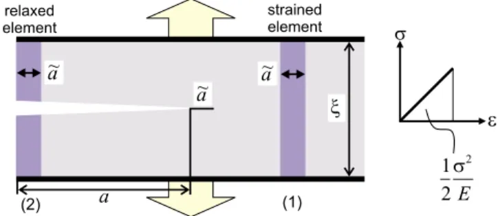
We now put the concepts discussed previously into a simple mathematical model, here done specifically for a crack in a brittle material. Cracks are one of the most prominent flaws in materials, representing either inclu-sions of void within materials or regions of weak adhe-sion. Figure 2 shows the basic energy balance during crack extension for a thin strip geometry, where a crack ranges half way through the material共also referred to as
a “semi-infinite crack”兲. The energy stored per unit vol-ume in the system is equal to the area under the stress-strain curve共see right panel in Fig.2兲, which for a linear
elastic material is equal to 122/ E. The energy stored in element 共1兲 of width a˜ ahead of the crack is given by
WP共1兲=1 2
2
Ea˜B, 共1兲
where B is the out-of-plane thickness of the specimen, is the width of the thin strip,is the applied stress, and
E is the Young’s modulus of the material共see right panel
in Fig.2, where= E兲. The energy stored in element 共2兲 is
WP共2兲= 0 共2兲
since it is completely relaxed 共as no traction is applied once the atomic bonds are broken兲. Therefore, during crack propagation by a distance a˜, the energy dissipated is given as
WP共1兲− WP共2兲=1 2
2
Ea˜B. 共3兲
This energy is used to create new surfaces, where this is commonly measured by the surface energy ␥ 共the sur-face energy measures the energy⌬E required to create a unit area surface⌬A,␥=⌬E/⌬A兲. Thus, the energy bal-ance condition is such that the change in energy given by Eq.共3兲 has to be equal to the total surface energy 2␥a˜B,
leading to the critical fracture condition 1
2
2
E= 2␥. 共4兲
Solving for the critical stress yields
Undeformed Stretching=store elastic energy Release elastic energy dissipated into breaking chemical bonds
(a)
(b)
FIG. 1.共Color online兲 Multiscale mechanisms of materials fail-ure.共a兲 Multiscale view of failure of glass, from macro to nano. 共b兲 Fracture can be envisioned as dissipation of elastic 共revers-ible兲 energy. This basic view of fracture holds for a very broad range of failure phenomena, from failure of the Earth during earthquakes, failure of engineering materials, to failure of pro-teins in cells, tissues, or organisms共Buehler and Xu, 2010兲.
FIG. 2. 共Color online兲 Basic energy balance during crack ex-tension, the basic mechanism of brittle failure共e.g., of a mate-rial such as glass兲 in a cracked solid under remotely applied load . The energy stored in element 共1兲 of width a˜ ahead of the crack is given by WP共1兲=12a˜B2/ E, where B is the out-of-plane thickness of the specimen, is the width of the thin strip, is the applied stress, and E is the Young’s modulus of the material共see right panel, where=E兲. The energy stored in element 共2兲 is WP共2兲= 0 since it is completely relaxed. During
crack propagation by a distance a˜, the energy of WP共1兲− WP共2兲
=12a˜B2/ E is dissipated. This energy is used to create two new material surfaces; thus 21a˜B2/ E = 2␥a˜B, leading to the critical fracture condition 122/ E = 2␥, or in terms of the ap-plied stress=
冑
4␥sE /.=
冑
4␥E/. 共5兲 Equation共5兲 thereby provides an equation that enablesus to predict the stress at which a material with a crack will begin to fail. The key issue here is to note that the basic physics behind fracture initiation is not controlled by a stress criterion, but rather by a critical energy re-lease condition. In this spirit we can more generally de-fine the so-called energy release rate G, which denotes the energy dissipated during fracture per unit of newly created fracture surface area,
G = −U共A兲
A , 共6兲
where A = a˜B and U is the energy available for crack growth, expressed as a function of the crack surface area
A 关where U=−21a˜B2/ E or U共A兲=−1
2A2/ E兴.
Equa-tion共6兲 can be rewritten as a discrete differential as
G = −⌬U共A兲 ⌬A = 1 共a˜2− a˜1兲B 1 2 2 E共a˜2− a˜1兲B = 1 2 2 E. 共7兲 The onset of fracture is then characterized by the condi-tion
G = 2␥, 共8兲
which resembles the condition expressed in Eq. 共4兲.
Ir-win for the first time put the concept of the energy re-lease rate outlined above into a mathematical frame-work that is generally applicable for a variety of geometries and loading cases 共Griffith, 1921; Irwin, 1957兲. Thus Eq. 共8兲 is typically referred to as the Griffith
condition.
This theory describes the stability condition for cracks; once the Griffith condition is reached a small crack can propagate through the material, leading to overall catastrophic failure as the crack growths uncon-trollably. This thermodynamical model can capture the link between bond breaking共expressed through the sur-face energy兲 and the overall stored energy 共expressed through the energy release rate兲. The fracture surface energy can typically be computed from bond properties and the geometry of the crack plane with respect to the microstructure of the material, or alternatively from atomistic simulations. It is noted, however, that in many materials the creation of new fracture surfaces is not the only dissipation mechanism. For example, crack exten-sion may be associated with amorphization at the crack tip, crack surface reconstructions, or lattice reorganiza-tion mechanisms. In these situareorganiza-tions, the condireorganiza-tion G = 2␥ should be modified to include other dissipation mechanisms characterized by ␥diss, leading to G = 2␥
+␥diss. Comparing this with Eq.共4兲 or Eq. 共8兲 shows that
the critical fracture stress increases as additional dissipa-tion mechanisms appear, leading to
=
冑
2共2␥+␥diss兲E/. 共9兲Indeed, many materials engineering approaches to in-crease the strength of materials are based on the concept
of introducing additional dissipation mechanisms to pre-vent cracking, realized by adding small particles or alloy-ing elements.
At a fundamental molecular scale, the most basic ma-terials failure phenomena can be attributed to several basic atomistic mechanisms, including rupture of bonds to create new surfaces and sliding of bonds along a cleavage plane. Figure 3 shows an overview over both mechanisms. Glass, for example, has an amorphous mi-crostructure where an orderly crystal structure is not present. In glass, failure occurs due to brittle fracture, atomic bonds break catastrophically through the mate-rial while creating new matemate-rial surfaces once a critical loading condition is reached. The critical condition can be predicted by Griffith model for brittle fracture as out-lined above共Griffith, 1921兲. In the case of a metal paper
wire, for instance, one made of copper, we find an or-derly face-centered cubic 共fcc兲 crystal structure in the material. This allows reorganization of the material dur-ing failure through slippdur-ing of bonds 共as opposed to FIG. 3. 共Color online兲 Physical mechanisms of failure in duc-tile共a兲 and brittle 共b兲 materials, representing two fundamental failure modes. In both cases, dissipation of stored elastic en-ergy drives the failure process. However, the mechanism of energy dissipation is different in the two cases. In共a兲, disloca-tions are the key dissipative mechanism共shown by the ⬜ sym-bol兲. In 共b兲 the extension of the crack through the creation of new material surfaces is the governing energy dissipation mechanism. The existence of a stress concentration around a cracklike defect shown in 共c兲 leads to locally much higher stresses than those found further away from the crack共stress is denoted by, and the distance from the crack tip denoted by r兲. These local stresses can cause cracks to extend as the large interatomic forces induce bond breaking关共b兲, as in brittle ma-terials兴 or bond shearing 关共a兲, as in ductile materials兴 共note that the stress concentration appears at cracks or flaws in any solid, regardless if it is brittle or ductile兲.
breaking兲 through crystal planes, a phenomenon known as dislocations. The reorganization of the lattice struc-ture remains after the load is removed, leading to a per-manent change of the shape of a material. This alterna-tive microscopic deformation mode leads to what is known as ductile failure, where a large amount of en-ergy dissipation occurs due to dislocation motion during plastic deformation, before fracture processes take place. Specifically, the emergence of dislocations in-crease ␥diss, which leads to an increased resistance of materials to catastrophic failure关see Eq. 共9兲兴. This
me-diates the repeated motion of dislocations through a ma-terial, which can lead to thinning共typically referred to as necking兲 that eventually leads to fracture of the mate-rial. However, since these processes require more strain until they lead to catastrophic failure, ductile materials tend to be more robust with respect to the ability to tolerate large deformation.
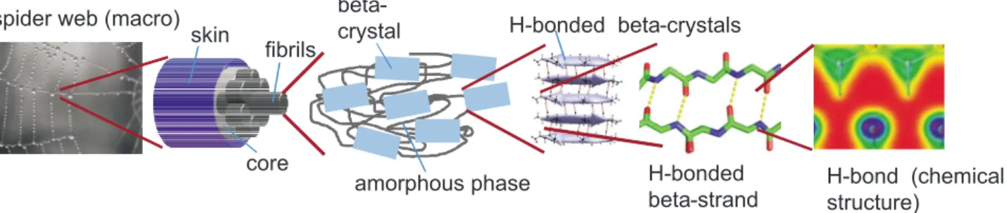
Mechanisms can be much more diverse and complex, however, in materials with a more intricate structural makeup. In the case of biological materials such as cells, bone, or spider silk共see Fig.4兲, the structural makeup of
the material is extremely complex and ranges through multiple scales via the formation of hierarchical struc-tures, involving both strong covalently bonded polypep-tide chains and a myriad of weaker interactions such as salt bridges, van der Waals forces, and quite importantly hydrogen bonds共H bonds兲. Failure of the material is yet again linked to atomistic mechanisms such as protein unfolding, molecular rupture, or sliding of biological molecules or biomolecular assemblies. Unlike other 共pri-marily engineering兲 materials, our understanding of how biological materials fail under external force is limited, and the theoretical framework for understanding cross-scale interactions in these materials is not yet unified. Continuum approaches empirically describe their me-chanical behavior at the tissue and in some cases the cellular level, whereas biophysical theories are confined to explaining protein rupture in a case specific manner at the molecular level. As in engineering materials, the coupling between different scales is fundamentally im-portant in understanding the mechanical properties of biological materials. Specifically, the concept of increas-ing the resistance to fracture by introducincreas-ing additional
dissipation mechanisms as shown in Eq.共9兲 plays an
im-portant role in understanding the material properties of biological tissues such as bone, nacre, or tendon. These materials have the capacity to dissipate much more en-ergy than that associated with a single fracture surface or the nucleation of dislocations. Rather, numerous dis-sipation mechanisms are facilitated by the distinct levels of hierarchical structures found in biological materials. This type of behavior has been studied, for example, to explain the great toughness of bone共Ritchie et al., 2009兲
or the remarkable extensibility and flaw tolerance of protein networks in cells and tissues 共Ackbarow et al., 2009兲.
III. ATOMISTIC AND MOLECULAR MODELING OF MATERIALS FAILURE
The fact that failure is directly linked to distinct ato-mistic mechanisms makes atoato-mistic and molecular level modeling an indispensable tool for studying how things break. A discussion on how this is done theoretically and computationally for different types of materials is central to this Colloquium, but before proceeding fur-ther, it is worthwhile to describe the theoretical basis of molecular simulation methods. For the sake of brevity here we focus primarily on molecular dynamics simula-tion, a selection of force fields and a brief overview of multiscale approaches through coarse-graining tech-niques. Molecular dynamics共often referred to as MD兲 is a suitable tool for elucidating the atomistic mechanisms that control deformation and rupture of chemical bonds at nanoscale, and for relating this information to macro-scopic materials failure phenomena关see, e.g., review ar-ticles and books 共Vashishta et al., 1999;Rountree et al., 2002;Buehler, 2008兲, and recent articles from our group
that describe large-scale MD simulation of brittle frac-ture mechanisms 共Buehler, Duin, and Goddard, 2006;
Buehler and Gao, 2006a, 2006b; Buehler et al., 2007兲兴.
The objective of MD techniques is to simulate the mo-tion of a group of atoms, generally representing the frac-tion of a larger system, to observe a critical phenomenon of interest, and/or to get an estimate of the global system properties. skin core fibrils beta-crystal amorphous phase H-bonded beta-crystals spider web (macro)
H-bonded beta-strand
H-bond (chemical structure)
FIG. 4. 共Color online兲 Schematic views of the hierarchical structure of spider silk and its fundamental beta-sheet protein building blocks 共Keten et al., 2010兲. A spider web, a spider silk fiber, the microstructure of a spider silk fiber, and a detailed view of
beta-sheet crystals, as well as individual H-bonded beta-strands that make up beta-sheet crystals are shown. The particular hierarchical structure of biological and natural materials makes it challenging to develop fracture models; mechanisms of failure and energy dissipation may occur at multiple scales and cannot be identified easily. Spider web image courtesy Nicolas Demars.
The basic concept behind MD is to calculate the dy-namical trajectory of each atom in the material using atomic interaction potentials that describe attractive and repulsive forces in between pairs or larger groups of at-oms. The interaction potentials are generally based on a mix of empirical data and first-principles based informa-tion such as quantum mechanics calculainforma-tions. Solving each atom’s equation of motion according to F = ma, po-sitions ri共t兲, velocities vi共t兲, and accelerations ai共t兲 are
calculated at each step, leading to atom trajectories that can reveal overall dynamics of the system as well as properties such as viscosity, bulk modulus, or fracture toughness. The total energy of the system is written as the sum of kinetic energy共K兲 and potential energy 共U兲,
E = K + U, 共10兲
where the kinetic energy is given by
K =1
2m
兺
j=1N
vj2. 共11兲
The potential energy is a function of the atomic coordi-nates rj,
U = U共rj兲, 共12兲
with a properly defined potential energy surface U共rj兲. The forces and accelerations are related by ai= fi/ m. The
forces are obtained from the potential energy surface— sometimes also called force field共or potential兲—as
F = md
2r
j
dt2 = −ⵜrjU共rj兲, j = 1, ... ,N. 共13兲
The numerical problem to be solved is a system of coupled second-order nonlinear differential equations which can only be solved numerically for more than two particles, N⬎2. Typically, MD is based on updating schemes that yield new positions from the old positions, velocities, and the current accelerations of particles. For instance, in the commonly used Verlet scheme, this can be mathematically formulated as
ri共t0+⌬t兲 = − ri共t0−⌬t兲 + 2ri共t0兲 + ai共t0兲共⌬t兲2+ O共⌬t4兲.
共14兲 The basic approach is shown in Fig. 5共a兲. Various fast numerical integration schemes are employed to solve the equations of motion and simulate a large ensemble of atoms representing a larger material volume; how-ever, in particular for all-atom simulations, high-frequency vibrations of light atoms requires a time step in the order of femtoseconds 共1 fsec⫽10−15sec兲 for
ac-curate and numerically stable calculations. This limits the application of full-atomistic MD methods to nano-meter size systems, at submicrosecond time scales 共it is noted, however, that simulations in excess of hundreds of ns typically run for weeks or months兲.
The application of the MD method to long-time scale deformation and failure phenomena such as creep or fatigue, or protein folding, is particularly challenging due to the time scale issue. In recent years progress has
been made to enable atomistic and molecular level simulation of such long-time phenomena, where the methods are potentially applicable to both crystalline materials and polymers or proteins 共Laioa and Par-rinello, 2002; Voter et al., 2002; Kushima et al., 2009;
Lau, Kushima, et al., 2009兲. Many of these applications
are based on statistical models and include various levels of approximation for long-time scale mechanisms共Alava
et al., 2006兲. One of the key issues of MD is that a system
may be trapped in a local energy minimum, and that the escape out of the local minimum is hindered due to the lack of accessible time scales共effectively suppressing the exploration of the entire state space兲. However, in order to simulate certain phenomena such as protein folding, it is essential that the entire space of possible configura-tions can be explored. Some methods关e.g., the metady-namics approach, applied to protein modeling 共Laioa and Parrinello, 2002兲兴 overcome this limitation by
en-abling the system to escape out of local energy traps. Other approaches such as the replica exchange method facilitate a more extensive exploration of the state space by running copies of the system at multiple tempera-tures, effectively enabling us to simulate the long-term behavior of molecular assemblies. The autonomous ba-sin climbing method is an algorithm that enables climb-ing out of potential minima, extendclimb-ing the metadynam-ics approach 共Laioa and Parrinello, 2002兲 towards
applications of modeling crystals and liquids and thereby facilitates the simulation of mechanisms such as creep in solids and viscosity effects in liquids at vast time scales. Aside from limitations with respect to the system size and the accessible time scale, MD has another important limitation related to the availability of interatomic po-tentials for a specific material. These potential functions must be able to model the characteristic type of
chemi-x
y
r( )t
v( )t
a( )t
Point representation stretching bending rotation Energy attraction repulsionr
0r
equilibrium bond distance(b)
r
(a)
FIG. 5. 共Color online兲 Basic approach of the molecular dy-namics simulation method. 共a兲 Atomistic structure 共neutrons, electrons, and protons兲 replaced by a point representation in the molecular dynamics approach. 共b兲 Illustration of the en-ergy decomposition in classical molecular dynamics force fields, along with a representation of a simple potential func-tion between pairs of atoms.
cal bonding, which can be a limiting factor for the appli-cability of the MD method. Materials such as silicon, iron, and steel, or colloidal systems 共e.g., cement兲, as well as some polymers pose particular challenges with respect to the development of models for their chemical interactions and reactions. For modeling fracture this is-sue is particularly critical, as it involves bond breaking and bond rearrangements at the crack tip, which re-sembles a chemical reaction 共think of bond breaking as the reverse reaction to bond formation in the synthesis of a molecule from its basic atomic constituents兲.
One of the strengths and a unique feature of atomistic methods is its very fundamental viewpoint of materials phenomena, a feature that is particularly important for failure processes. The only physical law that is put into the simulations is Newton’s law and a definition of how atoms interact with each other. Despite this simple basis, very complex phenomena can be simulated. Unlike many continuum mechanics approaches 共such as finite element methods兲, atomistic techniques require no a
pri-ori assumptions about the macroscale material
descrip-tion 共e.g., elastic properties, linearity, isotropy, etc.兲. Once the atomic interactions are chosen according to the specific bond properties and the chemical and struc-tural makeup of the material, the material behavior is determined, and mechanisms operating at multiple ma-terial scales are naturally captured共provided that a suf-ficiently large sample is simulated兲. Recent advances in computational power now enable the simulation of bil-lions of particles in massively parallelized MD simula-tions implemented on petaflop supercomputers, reach-ing dimensions on the order of micrometers 共Sanbonmatsu and Tung, 2007兲. We now proceed with an
in-depth discussion of a variety of potential formulations and then discuss strategies used to bridge through even larger ranges of scales in length and time than possible by using pure atomistic models.
A. Conventional and reactive force fields
All-atom force fields are predominantly used in mo-lecular dynamics simulations of materials at the nano-scale, as they generally are the most reliable yet compu-tationally efficient way of studying dynamics of materials and molecules. A wide range of force fields and simula-tion programs are currently available, most notably em-bedded atom models for metals, and force fields specific to organic compounds and biomolecules such as the DREIDING, AMBER,CHARMMforce fields, and programs, the OPLS force field. The GROMOS/GROMACS 共Van der Spoel et al., 2005兲 packages are also commonly used in
all-atom molecular dynamics. The NAMD共Nelson et al., 1996兲 program is a popular code that is capable of
car-rying out computations usingCHARMMand other force fields. For the sake of brevity, the main aspects of the CHARMM force field will be discussed here; the basic concepts of the MD technique and force field formula-tions are common to all packages used in the field关for a general review, see, for instance,Ponder and Case共2003兲
andMackerell共2004兲兴.
TheCHARMMforce field is widely used in the protein and biophysics community, and provides a reasonable description of the behavior of proteins. The parameters in force fields are often determined from more accurate quantum chemical simulation models by using the con-cept of force field training共Goddard, 2006兲. Parameters
for theCHARMMforce field have been meticulously op-timized and revised over the years, taking into consider-ation a wide variety of input including ab initio results 关e.g., via density functional theory 共DFT兲兴, experimental crystal structures and geometries, as well as vibrational spectra共MacKerell et al., 1998兲.
The CHARMM potential includes bonding and non-bonding共interaction兲 terms to describe short- and long-range forces between particles, where the contributions to bond stretching, bending, and rotation are individu-ally expressed. For example, for the three contributions in the plot shown in Fig. 5共b兲, simple mathematical expressions are used. For bond stretching Kb共b−b0兲2,
for bond bending K共−0兲2, and for bond rotations K关1+cos共n−␦兲兴. In addition to these three examples, several other terms are included to model the chemical properties of proteins and nucleic acids correctly. In the CHARMM model, the mathematical formulation for the empirical energy function that contains terms for both internal and external interactions has the form
U共Rជ兲 =
兺
bonds Kb共b − b0兲2+兺
UB KUB共S − S0兲2 +兺
angle K共−0兲2+兺
dihedrals K关1 + cos共n−␦兲兴 +兺
impropers Kimp共−0兲2 +兺
nonbond 冋
冉
Rmin共i,j兲 rij冊
12 −冉
Rmin共i,j兲 rij冊
6册
+ qiqj 1rij , 共15兲where Kb, KUB, K, K, and Kimp are the bond, Urey-Bradley, angle, dihedral angle, and improper dihedral angle force constants, respectively; b, S,,, and are the bond length, Urey-Bradley 1,3-distance, bond angle, dihedral angle, and improper torsion angle, respectively, with the subscript zero representing the equilibrium po-sitions for the individual terms.
The Coulomb and Lennard-Jones 6-12 terms consti-tute the external or nonbonded interactions; is the Lennard-Jones well depth, Rmin共i,j兲 is the distance at the
Lennard-Jones minimum, qiis the partial atomic charge,
1 is the effective dielectric constant, and rij is the
dis-tance between atoms i and j. In theCHARMMforce field, no additional terms are used for H bonds, since the com-bination of charge and Lennard-Jones contributions were verified to be adequate for describing protein, sol-vent, and interface hydrogen bonding. In all-atom force fields, water molecules are generally also treated explic-itly. Parameters of the force field generally are specified considering a specific water model共e.g.,TIP3Pmodel for
CHARMM兲 共Ponder and Case, 2003;Mackerell, 2004兲. TheCHARMMforce field belongs to a class of models with similar descriptions of the interatomic forces; where other models include the DREIDING force field 共Mayo et al., 1990兲, the UFFforce field共Universal Force Field兲 共Rappe et al., 1992兲, or theAMBERmodel共 Pearl-man et al., 1995; Wang et al., 2001兲. As discussed, in
CHARMMand other classical force fields, bonded terms are modeled with harmonic springs or its variations, and therefore cannot be modified 共e.g., towards a different chemical state, such as from sp2 to sp3兲 or broken once
defined by the connectivity input obtain from the topol-ogy of the molecule. Further, the atomic charges are fixed and cannot change during a simulation. These sim-plifications improve the simulation speed drastically and are not a major issue for most simulations studying con-formational changes of proteins under ambient physi-ological conditions. On the other hand, simulations in extreme conditions such as mechanical perturbations 共e.g., protein unfolding studies where the breaking of covalent bonds is involved兲 or modeling the properties under the exposure to harsh chemical environments may require reactive force fields that can take into account changes in fixed charges of the molecules, the formation and breaking of new bonds and variations in the bond order 共e.g., single versus double bond兲 共Stuart et al., 2000;Duin et al., 2001;Brenner et al., 2002兲. We refer the
interested reader to review articles for additional infor-mation, in particular regarding force field models共Wang
et al., 2001;Mackerell, 2004;Scheraga et al., 2007;Deniz
et al., 2008兲.
Reactive force fields represent a milestone in over-coming the limitations of classical “nonreactive” force fields, specifically their lack of the ability to describe rupture and formation of covalent bonds and their limi-tations in modeling chemical reactions. This is because the covalent bond terms are described using harmonic terms关see, for example, Eq. 共15兲兴, which do not provide
an accurate description of the bond energetics at large bond stretch and during reformation of new bonds. For failure properties of materials共which naturally involves large bond deformation and bond rupture mechanisms兲, this translates into the properties of molecules at large strain, a phenomenon also referred to as hyperelasticity. These effects can have profound impact for materials failure mechanisms, as illustrated in Gao 共1996兲 and
Buehler et al.共2003兲for crystalline brittle materials. Sev-eral flavors of reactive potentials have been proposed in recent years共Stuart et al., 2000;Duin et al., 2001; Bren-ner et al., 2002兲. The ReaxFF formulation of reactive
potentials, originally only developed for hydrocarbons 共Duin et al., 2001兲, have now been extended to cover a
wide range of materials, including metals, semiconduc-tors, and organic chemistry in biological systems such as proteins 共Duin et al., 2003; Strachan et al., 2003, 2005;
van Duin et al., 2004;Chenoweth et al., 2005;Cheung et
al., 2005;Han et al., 2005;Nielson et al., 2005;Buehler,
Duin, and Goddard, 2006;Buehler, 2007b;Buehler et al., 2007兲. To describe the details of bond stretching and
breaking, a bond length–bond order relationship is
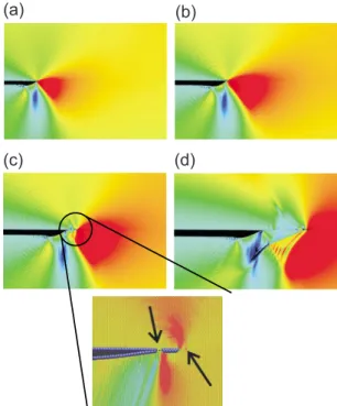
em-ployed to obtain smooth transition from nonbonded to single, double, and triple bonded systems. All connectivity-dependent interactions共that means valence and torsion angles兲 are formulated to be bond-order de-pendent. This ensures that their energy contributions disappear upon bond dissociation so that no energy dis-continuities appear during reactions. Similar to the CHARMM model, the reactive potential also features nonbonded interactions 共shielded van der Waals and shielded Coulomb兲. The reactive formulation uses a geometry-dependent charge calculation scheme that ac-counts for polarization effects and modeling of charge flow, assigning a partial charge to each atom at each integration step and thereby includes important quan-tum mechanical details about interatomic bonding. Due to the increased complexity, reactive potentials can be about 20–30 times more expensive than conventional models. A comprehensive review of reactive force fields for modeling failure is beyond the scope of this Collo-quium, partly because different materials require signifi-cantly unique modeling methods and potentials. In the following we present two examples that illustrate the significance of using reactive force fields in describing the failure of a crystal of silicon and a protein molecule. Figure 6 shows how a reactive force field has been applied to describe fracture of silicon under tensile load 关loading condition, see Fig.6共a兲兴, where a more accurate description of the details of chemical bonding has proven to be crucial to match simulations of silicon frac-ture with experiment 共Buehler, Duin, and Goddard, 2006;Buehler et al., 2007兲. In the example shown in Fig. 6, a hybrid multiparadigm technique was used where the computationally expensive ReaxFF model was only used in a small region surrounding the crack tip, while the rest of the domain was described using a computation-ally less expensive Tersoff potential. The advantage of this algorithm is that it dynamically identifies regions in the simulation domain that undergo large deformation, where the ReaxFF description is mandatory in order to provide an accurate representation of the changes of the bonding characteristics under large stretch. Further-more, the comparison between a pure Tersoff model and the hybrid ReaxFF-Tersoff model shown in Fig. 6共b兲 il-lustrates the significance of providing an accurate repre-sentation of chemical bond breaking events for model-ing fracture. The failure of the Tersoff potential to accurately model the details of bond breaking under large stretch explains why the crack does not extend in this case, in contrast with experimental results. Including a fully reactive full chemistry description through the use of ReaxFF close to the crack tip共where bond break-ing occurs兲 provides an accurate representation of crack dynamics, in agreement with experimental studies 关for further details see Buehler, Duin, and Goddard 共2006兲
andBuehler et al.共2007兲兴.
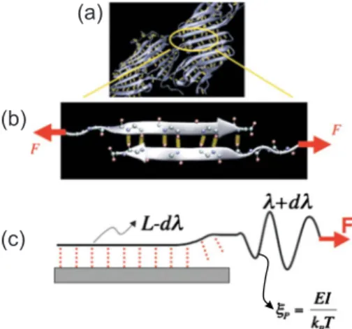
Figure7shows the results of stretching and breaking a small protein molecule with covalent cross links under tensile loading 共Buehler, 2007b兲. The study shown here
reveals the differences between a nonreactive 共CHARMM兲 force field and the ReaxFF reactive force
field. Figure7共a兲shows snapshots as the molecule is be-ing stretched, modeled usbe-ing the reactive model. As the molecule is being pulled, the covalent cross-links 共disul-fide bonds兲 within the molecule break. These breaking points correspond to the peaks in the force-extension plot shown in Fig.7共c兲, and the force drops significantly after each breaking point as the elastic energy stored in the protein is released. In the case of the CHARMM model 关Fig. 7共b兲兴, bond breaking cannot be described, and the force continues to rise once the covalent cross-link within the protein is being stretched关see Fig. 7共c兲兴.
The results shown here clearly illustrate the significance of a reactive force field approach in modeling the failure of molecules, specifically when the breaking of covalent bonds is involved.
B. Multiscale simulation techniques
Albeit providing a rather accurate description of mac-romolecules, all-atom modeling approaches have histori-cally been prohibitively extensive when large systems and long simulation times must be considered. This led to the development of coarse-grained models 共Tozzini, 2005兲, which provide a simplified representation of
mac-romolecules employing less degrees of freedom and simple bonded and nonbonded interactions that can be more rapidly calculated in each time step 共see Fig. 8兲.
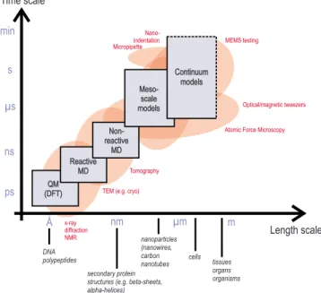
The integrated use of simulation methods with different computational expense and accuracy is referred to as multiscale modeling, where a systematic link is estab-lished between multiple scales. The concept is shown in Fig. 9, including the representation of handshaking be-tween different methods to pass information systemati-cally from lower levels to coarser, larger scales. The fig-ure also plots relevant experimental techniques that overlap with corresponding computational techniques.
Coarse-grained models have so far been successfully applied to a wide range of problems including protein folding, allostery, aggregation, and molecular biome-chanics, and multiscale description of complex materials such as bone. The various approaches used in particular
Tersoff ReaxFF Fixed boundary atoms (a) (b)
FIG. 6. 共Color online兲 Multiparadigm molecular dynamics simulation of dynamic fracture of silicon 共Buehler, Dodson, Meulbroek, Duin, and Goddard, 2006; Buehler, Duin, and Goddard, 2006; Buehler et al., 2007兲, carried out based on a
pure Tersoff model and a hybrid ReaxFF-Tersoff model. The hybrid model schematically shown in共a兲 describes the fracture mechanics of silicon by a combination of a simple Tersoff force field in regions far away from bond rupture events, with the ReaxFF reactive force field used to more accurately describe the rupture processes at the crack tip.共b兲 Comparison between 共left兲 the pure Tersoff model and 共right兲 the hybrid ReaxFF-Tersoff model. In the pure ReaxFF-Tersoff model the crack does not extend, in contrast with experimental results. In the hybrid model where an accurate representation of the chemistry of bond breaking is provided at the crack tip, the crack extends under application of load. This comparison illustrates the sig-nificance of providing an accurate representation of chemical bond breaking events for modeling fracture.
FIG. 7. 共Color online兲 Breaking a single protein molecule by pulling at the ends of a small protein共␣ conotoxin PnIB from conus pennaceus; PDB identification code 1AKG兲 共Buehler, 2007b兲. The study shown here reveals the differences between
a nonreactive共CHARMM兲 force field and the ReaxFF reactive
force field. 共a兲 Snapshots as the molecule is being stretched, modeled using the reactive model共ReaxFF兲. As the molecule is being pulled, the covalent cross-links共disulfide bonds兲 within the molecule break. These breaking points correspond to the peaks in the force-extension plot shown in 共c兲; and the force drops significantly after each breaking point as the elastic en-ergy stored in the protein is released. In the case of the
CHARMMmodel共b兲, bond breaking cannot be described, and
the force continues to rise once the covalent cross-link within the protein is being stretched共c兲.
for biological materials are reviewed here. Single-bead models are perhaps the earliest approach taken for studying macromolecules. The term single bead derives from the idea of using single beads共masses兲 for describ-ing each amino acid in a protein structure. The elastic network model共ENM兲 共Tirion, 1996兲, Gaussian network
model 共Haliloglu et al., 1997兲, and the Go-like model
共Hayward and Go, 1995兲 are well-known examples of
this simplistic approach. Simple models such as ENM and Go-like models treat each amino acid as a single bead located at the C␣ position with mass equal to the mass of the amino acid. The beads are interconnected by harmonic or nonlinear springs representing the co-valently bonded protein backbone. In the Go-like mod-els, an additional Lennard-Jones term is included in the potential to describe short-range nonbonded native in-teractions between atoms within a cutoff distance. De-spite their simplicity, these models have been extremely successful in explaining thermal fluctuations of proteins 共Tozzini, 2005兲 and have also been implemented to
model the unfolding problem to elucidate atomic-level details of deformation and rupture that complement ex-perimental results 共West et al., 2006; Sulkowska and Cieplak, 2007;Dietz and Rief, 2008兲. A more recent
di-rection is coupling of ENM models with a finite element-type framework for mechanistic studies of protein struc-tures and assemblies共Bathe, 2008兲. Due their simplicity,
single-bead models have several shortcomings. With classic ENM, only harmonic deviations from the initial configuration are possible. In the Go model, native in-teraction definitions lead to a minimally frustrated land-scape which is highly biased towards the input configu-ration of the molecule. Such models therefore cannot predict folding or unfolding intermediates and
meta-stable states. The explicit treatment of protein-solvent interactions, non-native interactions and H bonds is also not possible with single-bead models. It is now widely accepted that for protein unfolding studies, the results obtained using such models are only qualitative at best, although they may reveal important aspects of topology-dependent mechanical resistance 共West et al., 2006;
Sulkowska and Cieplak, 2007;Dietz and Rief, 2008兲, and
can thus be used to improve our understanding of structure-property links.
Using more than one bead per amino acid can lead to a more detailed description of macromolecules. In the simplest case, the addition of another bead can be used to describe specific side-chain interactions 共Bahar and Jernigan, 1997; Marrink et al., 2007; Monticelli et al., 2008兲. Four to six bead models capture even higher
amount of detail by explicit or united atom description for backbone carbon atoms, side chains, carboxyl, and amino groups of amino acids. A successful implementa-tion of this approach is the coarse-grained models devel-oped for studying folding and aggregation in proteins using discontinuous molecular dynamics 共Nguyen and Hall, 2004,2006兲. Although multibead models have
su-perior qualities compared to single-bead descriptions, dozens of additional energetic terms involving pseudo-FIG. 8. 共Color online兲 Illustration of coarse-graining approach
for a simple one-dimensional fibrillar protein filament 共col-lagen兲. This schematic shows how a full atomistic representa-tion is coarse-grained and used in a mesoscale model formula-tion. This mesoscale model formulation enables one to reach much larger time and length scales. The systematic parametri-zation from the bottom up provides a rigorous link between the chemical structure of proteins共for example, through their amino acid sequence兲 and the overall functional material prop-erties. This computational approach is a key component in the advancement of materiomics as it provides us with the ability to reach microsecond and micrometer length scales.
nm Å µm m ns µs s Nano-indentation Optical/magnetic tweezers
Atomic Force Microscopy
Time scale Length scale MEMS testing x-ray diffraction NMR
TEM (e.g. cryo)
DNA polypeptides
secondary protein structures (e.g. beta-sheets, alpha-helices) nanoparticles (nanowires, carbon nanotubes cells min Micropipette Reactive MD Reactive MD ps Meso-scale models Meso-scale models Continuum models Continuum models Non-reactive MD Non-reactive MD QM (DFT) QM (DFT) tissues organs organisms Tomography
FIG. 9. 共Color online兲 Experimental, theoretical, and compu-tational tools for the characterization and modeling of defor-mation and failure of materials, plotted over their respective time and length scale domain of applicability. Experimental methods include x-ray diffraction, TEM共transmission electron microscopy兲, AFM 共atomic force microscopy兲, OT/MT 共optical/magnetic tweezers兲, and MEMS 共mechano-electro-mechanical system兲 testing, as well as nanoindentation. Fre-quently used theoretical and simulation tools include quantum mechanics共DFT兲, molecular dynamics, coarse-grained models, mesoscale atomistically informed continuum theories, and con-tinuum models. The lower part indicates respective classes and scales of materials that can be studied with these types of tech-niques. Adapted fromBuehler and Yung, 2009.
bonds and other means to avoid complex dihedral or improper potentials that stabilize the conformation of the polypeptide chain have to be introduced for generic models. Even with the introduction of these terms, some of which are physically not intuitive, the models offer limited applicability, as the defined side chain interac-tions are only valid for simple residues such as glycine and alanine. More complex yet computationally efficient potentials that intrinsically take into account sequence specificity are extremely challenging to develop, thus making readily available all-atom descriptions and simu-lation packages more favorable for most applications. Practical methods of developing coarse-grained models that have wide applicability remain challenging for poly-mers and proteins in particular.
More recently, coarser-level modeling approaches have been applied to model biomolecular systems at larger time and length scales. These models typically employ superatom descriptions that treat clusters of amino acids as “beads,” as shown schematically in Fig.8
共for the case of tropocollagen molecules兲. In such mod-els, the elasticity of the polypeptide chain is captured by simple harmonic or anharmonic 共nonlinear兲 bond and angle terms. These methods are computationally quite efficient and capture shape-dependent mechanical phe-nomena in large biomolecular structures 共Arkhipov et
al., 2006兲, and can also be applied to collagen fibrils in
connective tissue共Buehler, 2006兲 as well as mineralized
composites such as nascent bone 共Buehler, 2007a兲.
Coarse-grained techniques based on results from QM or all-atom MD modeling approaches show great promise as they can run much faster than multiatom descriptions for molecular building blocks such as proteins and are relatively easier to implement than multibead potentials that require complicated energy terms for achieving the correct molecular geometry. Since such high-level preci-sion is not sought after in these coarser methods, simpler terms are generally used to achieve the global structure and dynamical information of the system.
In addition to methods that uniformly simplify a com-plex system by coarse graining, hybrid approaches that employ atomistic details at active regions of biomolecu-lar systems or crystalline solids as shown in Fig.6in the silicon fracture example also show great promise共Neri et
al., 2005兲. The use of hybrid approaches in protein
mod-eling has been pioneered early on through the use of so-called QM-MM methods共where quantum mechanical descriptions is used at enzymatic sites, and nonreactive models are used elsewhere in the protein兲. Overall, one can identify two fundamental viewpoints in multiscale modeling: 共1兲 Employing different levels of detail or fi-delity in a single model 共hybrid or concurrent ap-proaches兲, and 共2兲 enabling scale transitions by extrac-tion or passing of key informaextrac-tion 共i.e., parameters兲 to higher scales based on more accurate simulations at smaller scales共hierarchical approaches兲. Developing ac-curate models that can predict not only the overall struc-tural behavior but also processes such as bond forma-tion, self-assembly as well as molecular and macroscale failure of materials is an area of great interest for
phys-ics, materials science, and medical applications. Which of the two approaches 共i.e., hybrid or hierarchical ap-proach兲 is better suited depends strongly on the type of application and the specific properties that are simu-lated.
IV. CASE STUDIES: FAILURE OF MATERIALS, FROM NANO TO MACRO
In this section we present a review of failure mecha-nisms of three classes of systems, starting with earth-quakes 共failure of the Earth’s crust兲, focusing on bone, and finally discussing failure of molecules. We highlight commonalities between all three examples discussed here.
Bridging the gap between vastly different scales in a single model remains a challenge as cross-scale interac-tions and hand shaking between regions of different de-tail demand a rigorous theoretical basis and access to large-scale computational resources. For instance, incor-porating molecular-level detail in simulations of earth-quakes would be extremely challenging in this regard; however, studies of bone and single molecules based on bottom-up modeling approaches have become increas-ingly popular. Similar simulations can be carried out for macroscale systems using information passing across scales, for instance, by employing large representative particles共superatoms兲 as in the case of a coarse-grained model.
A. Failure of the Earth’s crust: Earthquakes
In earthquakes, the sudden rupture and slipping of the tectonic plates affects the ground’s ability to provide stable foundation for the built environment. Elastic waves emitted by these rupture processes may lead to strong vibrations of the ground, inducing great damage in bridges, buildings, and roads. Figure10shows the ba-sic fracture process associated with an earthquake. Two tectonic plates are slowly sheared against each other over the course of many years 共corresponding to re-motely applied loading兲, while elastic energy is stored in the system共through deformation of the crust兲. The elas-tic energy is suddenly released in a catastrophic event once the earthquake occurs as the two tectonic plates slides against each other, while energy is dissipated in frictional processes, which is characterized by propaga-tion of a cracklike rupture front. This process of energy storage and subsequent dissipation reflects the mecha-nism shown in Fig. 1共b兲.
Figure 11 shows the geometry of an earthquake in Kocaeli, Turkey, as it occurred in 1999 共Sekiguchi and Iwata, 2002兲. The plot shows the path of the earthquake
along a weak plane in the Earth’s crust. This earthquake spread almost linearly from the initiation point in Ko-caeli towards Eften Lake and Izmit Bay. Based on geo-physical measurements, geologists have also analyzed the dynamics of this rupture event, in order to identify the speed at which earthquakes occur. Figure 12shows the analysis of the position over time共and thereby
pro-viding immediate insight into the speed兲 of this earth-quake. The analysis shows that that the rupture propa-gates intersonically after a short initial phase of subsonic growth, with speeds in excess of several km/sec. The un-derstanding of dynamics of earthquakes is important to develop better models to predict future events; thereby, a precise knowledge of the speed of propagation and the path is crucial to estimate the resulting damage in infra-structure. For example, the occurrence of intersonic speeds results in shock fronts, with very strong and sud-den displacements of the crust. These types of mecha-nisms can lead to rather severe structural damage in natural and built infrastructure. Intersonic propagation of earthquakes was first observed in this Kocaeli
earth-quake, even though the possibility for the existence of this phenomenon has been proposed earlier based on theoretical studies 共Burridge, 1973; Andrews, 1976;
Freund, 1990兲.
The phenomenon of intersonic rupture propagation has been investigated further since the initial observa-tion in Turkey. In particular, experimental testing of so-called “laboratory earthquakes” put forth by a group at Caltech provide an excellent approach in further identi-fying underlying features and mechanisms 共Rosakis et
al., 1999;Rosakis, 2002;Xia et al., 2004,2005;Rosakis et
al., 2006兲. In these experiments 共setup shown in Fig.13兲,
the Earth’s crust is scaled down and modeled by a poly-mer slab, and the existence of tectonic faults is modeled using a weak plane in the polymer. Under application of shear and/or tensile or compressive loading, researchers have been able to identify important underlying mecha-nisms and dynamical events in this setting, such as the understanding the transition from subsonic to intersonic rupture propagation. Figure13confirms that laboratory earthquakes reveal a similar phenomenon leading to rupture propagation faster than the shear wave speed, as can be seen in Fig.13共c兲through the existence of shock fronts. Among other contributions, these experiments
San Andreas fault
FIG. 10. 共Color online兲 Basic fracture process associated with an earthquake, here exemplified for the case of the San An-dreas fault. Two tectonic plates are sheared against each other, while elastic energy is stored in the system, which is released in a catastrophic event once the earthquake occurs. Energy dissi-pation mechanisms include friction between along the fault line, where local slip occurs. Maps and photographs of the San Andreas fault courtesy of the U.S. Geological Survey共the de-tailed aerial view of the San Andreas fault is taken near Car-rizo Plain, Central California兲.
FIG. 11. Earthquake dynamics of the 1999 Kocaeli, Turkey earthquake 共Sekiguchi and Iwata, 2002兲. The plot shows the
path of the earthquake along a weak plane in the Earth’s crust. FromSekiguchi and Iwata, 2002.
FIG. 12. 共Color online兲 Analysis of the dynamics 共and speed兲 of the earthquake’s rupture front. The location 共distance兲 of the front of the earthquake is shown as a function of time. It propagates at a speed of approximately 3 km/ sec initially 共sub-sonic兲, then followed by a sudden jump to a much higher propagation velocities of around 5.8 km/ sec. This propagation is faster than the speed of shear wave 共thus referred to as “supershear” or “intersonic”兲. From Sekiguchi and Iwata, 2002.