HAL Id: cea-02569231
https://hal-cea.archives-ouvertes.fr/cea-02569231
Submitted on 11 May 2020HAL is a multi-disciplinary open access archive for the deposit and dissemination of sci-entific research documents, whether they are pub-lished or not. The documents may come from teaching and research institutions in France or abroad, or from public or private research centers.
L’archive ouverte pluridisciplinaire HAL, est destinée au dépôt et à la diffusion de documents scientifiques de niveau recherche, publiés ou non, émanant des établissements d’enseignement et de recherche français ou étrangers, des laboratoires publics ou privés.
Insight on electrical and thermal powers mix with a
Gen2 PWR: Rankine cycle performances under low to
high temperature grade cogeneration
H.D. Nguyen, N. Alpy, D. Haubensack
To cite this version:
H.D. Nguyen, N. Alpy, D. Haubensack. Insight on electrical and thermal powers mix with a Gen2 PWR: Rankine cycle performances under low to high temperature grade cogeneration. Energy, Else-vier, 2020, 202, pp.117518. �10.1016/j.energy.2020.117518�. �cea-02569231�
1
Insight on electrical and thermal powers mix with a Gen2 PWR: Rankine cycle
performances under low to high temperature grade cogeneration
H.D. Nguyen
1, N. Alpy
1,*, D. Haubensack
11CEA Cadarache, DEN/CAD/DER/SESI/LEMS, 13108 Saint-Paul-lez-Durance, France
huynh-duc.nguyen@cea.fr ; nicolas.alpy@cea.fr ; david.haubensack@cea.fr
Highlights
1. Performances of a Rankine PCS, typical from Gen2 PWRs fleet, are balanced under cogeneration. 2. Cogeneration heat is provided in a 146-285°C range and thermal load rates up to 20% of SGs power. 3. Investigated load and temperature grade extend the range from common cogeneration applications. 4. Calculations account for specifics of PCS thermodynamic irreversibilities at part-load.
5. Cycle electrical efficiency drops from 2.7 points for a 20% cogeneration load with a 285°C steam. 6. Extrapolation to a 50% load, rises the loss to 6.9 points.
7. Turbine part-load mechanisms and connected thermodynamics irreversibilities, are analysed. 8. Insight on electrical and thermal powers performance, is provided as first engineering guideline. 9. Computational methodology and multi-objectives optimization relevancy, are discussed.
Abstract
In the challenging framework for a carbon free energy mix achievement, performances of a Rankine cycle exemplary of Power Conversion Systems (PCS) from the Gen2 Pressurised Water Reactors (PWR) fleet, are mapped under heat cogeneration. Noticeably, cycle performances are investigated using the THERMOFLEX software that allows taking into account the thermodynamic irreversibilities balance within the PCS that arise from turbine part-load operation, with regards to the PCS performance at design which is optimized for a 100% electrical duty.
First, the technical scope of the paper is discussed together with the methodology. A peculiar methodological point is to investigate how deviations of thermodynamic irreversibilities under part-load alter calculation accuracy of cycle performances, depending on temperature grade and thermal load that are considered for cogeneration. To start with the simulation work, THERMOFLEX results are verified by comparison with CYCLOP in-house code, on a reference case chosen as exemplary of a 1300 MWe PWR’s PCS. Then, several cogeneration scenarios are computed with THERMOFLEX, differing from each other by location of the line proving heat for cogeneration (recovered as latent heat of steam condensation), to cover a 146 to 285°C range. Thermal load for cogeneration is also varied and rates up to 20% of Steam Generators (SG) ones. Hence, spanned cases extend the range of load and temperature grade from common cogeneration applications, such as district heating or water desalination. Inline, electrical power to the grid is mapped as a function of cogeneration thermal load, providing first engineering guideline about the mix performance.
It comes out from the most stringent cogeneration case which is studied, that cycle electrical efficiency drops from 2.7 points. Extrapolation of this result to a 50% load would significantly rise the loss to 6.9 points. Calculations are repeated with CYCLOP, which, contrary to THERMOFLEX (but similarly to a common approach in the applied engineering literature)performs thermodynamic calculations while disregarding part-load thermodynamic irreversibility aspects. Main mechanisms responsible for the discrepancy between both approaches, are analysed. It comes out that isenthalpic throttling valve which govern steam admission in the turbine, play a key role while degradation of turbine efficiency remain low in the investigated range. Turbine expansion lines are indeed shifted to lower pressures, by so decreasing turbine stage losses contribution due to steam moisture content and balancing other mechanisms of losses. Finally computational methodology and multi-objectives optimization relevancy, are discussed paving the way to next investigation of an extended range for electrical and thermal powers mix.
*: Corresponding author.
2
Keywords
Rankine cycle, Power conversion System, PWR, Power, Heat, Cogeneration, Turbine, Steam Generator, Part-load, Performance, Flexibility, Energy mix.
Abbreviations
APR Advanced Power Reactor CON Condenser
GFR Gas-cooled Fast Reactor HP High Pressure
HT High Temperature
HTR High Temperature Reactor IP Intermediate Pressure LP/BP Low Pressure LT Low Temperature
MED Multiple Effect Distillation
MS Moisture Separator
MSF Multi-Stage Flash distillation MT Medium Temperature NPP Nuclear Power Plant PCS Power Conversion System PWR Pressurised Water Reactor RH ReHeater
SFR Sodium Fast Reactor SG/GV Steam Generator
TVC Thermal Vapour Compression VHTR Very High Temperature Reactor
1. Introduction
The need for carbon free, electrical and thermal energies is a main target for climate stabilization and as such (Audoly, Vogt-Schilb, Guivarch, & Pfeiffer, 2018) reports that warming mitigation at any level from 1.5 °C to 3 °C requires the carbon content of electricity to become almost carbon-free before the end of the century. Connected challenges are integration in the electrical grid of a large amount of green energies and implementation of new energetic vectors, likely involving hydrogen production (Sheffield, Martin, & Folkson, 2014). In France, renewables capacity for electrical production has grown from 32 GW in 2010 to 48 GW in 2017 while nuclear capacity has remained unchanged to 63 GW (I-Tésé, 2018). Worldwide, renewables capacity rise is even larger from 1.226 TW in 2010 to 2.179 TW in 2017 (Irena, 2018). This panorama should generate new constraints and opportunities for Nuclear Power Plants (NPPs) cogeneration, (International Atomic Energy Agency, 2017). Indeed, French Pressurized Water Reactors (PWRs) have shown their technical ability, at reactor and fleet scales to accommodate grid demand fluctuation through load-following, typically according to nighttime, weekend and seasons specifics. Inline (Cany, Mansilla, G, & da Costa, 2018) proposes some neutronic control logic improvements to put-off the current limit that is faced at high nuclear fuel burn-up. Nevertheless, lowering the load factor to cope with the growing share of green but intermittent renewable energies may jeopardise the nuclear economics and could rise concerns about thermal ageing acceleration of some components, hence increasing the maintenance cost (Lokhov, 2011). Alternatively, cogeneration that would supply some key processes with thermal energy is analysed as a relevant economical strategy (Jasserand & Devezeaux de Lavergne, 2016) to relieve consequences of nuclear core reinforced part-load operation: instead, cogeneration could allow operating nuclear core at full regime while shifting power conversion cycle from electrical to thermal power production.
Worldwide, especially in Eastern Europe and in Japan, cogeneration from NPPs has been performed for decades, e.g. to provide district heating or to produce fresh water from the sea. As such, (International Atomic Energy Agency, 2007) reports that over 200 reactor-years of operating experience on nuclear desalination have been accumulated worldwide. In the frame of Generation 4 (Gen-4, 2019), R&D on cogeneration has been addressed since the 2000s especially with High and Very High Temperature Reactors (HTRs, VHTRs) (Hittner, Bogusch, Fütterer, de Groot, & Ruer, 2011) for which innovative Brayton power conversion cycles (typically, helium or supercritical CO2) could be considered. However, some significant R&D challenges still exist on materials to reach a nuclear grade (Hittner, Lommers, & Shahrokhi, 2012) so that short term cogeneration possibility from proven PWRs technology featuring a steam Rankine cycle, still needs to be considered (Leurent, et al., 2017).
3 In France, NPPs deployment targets historically to cover base-load of the electricity demand: as such, nuclear power in the national electric portfolio is as high as 78% in 2017 with 379 TWh produced for a 482 TWh total electrical consumption (I-Tésé, 2018). Inline, conception and operation of the French PWRs fleet (Grard, 2014) as well as safety simulations tools such as the CATHARE system code (Geffraye, et al., 2011) address the original electricity production duty. Thus, technical work on cogeneration remains actually in France at its conceptual stage while benefiting from outbreak effort (Safa, 2012).
To go further on the engineering side of cogeneration evaluation, the present work address the role of steam cycle part-load performance as regards actual operation and performance of a flexible unit that should be able to shift from a 100% electrical duty to cogeneration operation. It is a common practise for early thermodynamics evaluation on cogeneration (Le Pierres, Luo, Berthiaud, & Mazet, 2009), (Abdoelatef, Field, & Lee, 2015) to disregard turbine part-load impact on performance changes. As such, latter authors have interestingly investigated APR1400 coupling with a sea water desalinisation plant, by using IAEA-DETOP thermodynamic software (Sanchez-Cervera , Kavvadias, & Khamis, 2013) which consider only on-design performances. Their target was to compare thermodynamic performance of the nuclear coupling with thermal desalinisation process technologies among Multi-Stage Flash distillation (MSF) and Multiple Effect distillation, possibly with additional Thermal Vapour Compression (MED and MED-TVC). Typically, to achieve a 150000 m3/day production of fresh water with MED technologies, a 100-144 °C steam flow was extracted from the turbine low pressure group (see Figure 1) to provide 180-314 MWth to the desalination process. This correspond to less than 8% of the nuclear core thermal power. This study, which concludes to a 0.1 point gain on electrical efficiency for MED-TVC compare to MED, can be seen as exemplary of state of the art work from the applied engineering literature on cogeneration comparing thermodynamic performances among various engineering possibilities, by applying an on-design engineering approach.
Figure 1. Exemplary extraction points (red arrow) considered for APR1400 coupling with a desalination process, (Abdoelatef, Field, & Lee, 2015)
A peculiar point of the present work is instead to balance performance deviations that such an on-design approach is actually introducing and which could make poorly reliable any performance ranking that is concluded from its application. Indeed, as mentioned above, cogeneration objectives (temperature grade and thermal power load) that could be next assigned to NPPs to gain flexibility in a renewed energy mix context, are likely to be more stringent than mild ones considered for desalinisation or district heating such as in (Abdoelatef, Field, & Lee, 2015) work. Hence, it is proposed in the present work, based on a Rankine PCS exemplary of Gen2 PWRs fleet, to extend cogeneration load up to 20% of Steam Generators (SG) power and temperature grade for cogeneration to the higher one which is available from such a cycle, 285°C.
Inline, the paper is organised as follow:
– First, materials and methods are presented. Cycle calculations are supported by two software, CYCLOP (CYCLe OPtimisation) which is a CEA in-house code for on-design performance (Haubensack, Thévenot, & Dumaz, 2004) and THERMOFLEX which is a commercially available software for thermal engineering and covers on- and off-designs (Thermoflow, 2019).
– Second, to start with the simulation work, THERMOFLEX results are verified by comparison with CYCLOP in-house code, on a 1300 MWePWR PCS reference case that is built.
– Then, several cogeneration scenarios are computed with THERMOFLEX, differing from each other by location of steam flow extraction from the cycle. Inline, spanned cases address a large scope of cogeneration applications, in a 146 to 285°C temperature range. Thermal power that is made available for cogeneration is also varied up to 20% of SGs one’s. Same mappings of cycle performances under cogeneration are carried-out using CYCLOP. Main discrepancies between both
4 approaches are then analysed with some outcomes on computational methodology and multi-objectives optimization relevancy.
– Finally, turbine part-load mechanisms and connected thermodynamics irreversibilities, are analysed.
2. Materials, methods and steam cycle reference case
2.1. CYCLOP software modelling
CYCLOP is a CEA in-house code for on-design power conversion cycle modelling. It has been validated on Rankine steam cycles coupled to French Pressurized Water Reactors (such as CRUAS) and the French Sodium Fast Reactor (SFR) SUPERPHENIX. It has also been extensively benchmarked in the frame of R&D programs, from the helium Brayton cycle applied to a Gas-cooled Fast Reactors (GFRs) (Haubensack, Thévenot, & Dumaz, 2004) to the sc-CO2 cycle for SFRs, (Floyd, et al., 2013), (Pham, et al., 2015). The code features a material properties database that follows recommendations from the National Institute of Standards and Technology.
In CYCLOP, a cycle is represented by a set of fluid loops built from energetic components (heat source and sink, turbine, pump, compressor, ejector, heat exchanger, etc.) and hydraulic ones (pipe, valve, mixer, splitter, etc.). Components performance are defined by macroscopic parameters such as isentropic efficiency for turbomachinery, pinch point or efficiency for heat exchangers and pressure and/or heat losses for simpler hydraulic components. Noticeably, steam turbine isentropic efficiency given in dry conditions is corrected following the Baumann rule (Baumann, 1912) to account for efficiency deviation connected to steam moisture content.
This tool solves automatically mass and energy balances for all components of the cycle from a minimum set of input data, allowing all cycle parameters to be quickly modified and optimised using the deterministic Nelder-Mead algorithm (Nelder & Mead, 1965).
Similarly to DEOP-IAEA software, CYCLOP does not model components part-load performance: as such, when applied to a cogeneration case, components performances (such as turbine stage dry expansion efficiency, pipes and valves pressure loss, etc.) and pressure ratios of the turbine groups, are unduly kept unchanged and so equal to optimal values of the original 100% electrical duty design.
2.2. THERMOFLEX software modelling
THERMOFLEX is part of the THERMOFLOW thermal engineering software suite for power and cogeneration industries (Thermoflow, 2019). The code provides design point heat balance, physical equipment size and cost estimates with special emphasis on fossil, nuclear and solar power conversion cycles as well as on different desalination processes for cogeneration purpose. As for CYCLOP, steady states operation is modelled, not dynamic aspects. However, a main difference from CYCLOP makes THERMOFLEX a very relevant tool in the frame of the present work: specific models allowing simulating steam turbine and other components at part-load, are implemented. Recently, (Popov & Borissova, 2017) used such an ability to deal with different operating points for a given design. They investigated coupling of solar to nuclear systems and balanced the performance of nuclear steam superheat thanks to solar, while taking into account solar intermittent production impact.
It can be expected that THERMOFLEX has capitalized a fine databank on components on- and off-design performances, among various application fields, as the software is dating back from 1987. As such, (Manente, Rech, & Lazzaretto, 2016) used THERMOFLEX to design the steam turbine groups of their 153 MWe
concentrating solar power plant project (that was coupled to a natural gas power station). They compared the results with correlations from (Astvatsaturova, Zorin, & Trukhnii, 2015) who interestingly carried-out a review to provide a mean estimate of turbine performances with respect to already designed turbines. (Manente, Rech, & Lazzaretto, 2016) concluded to consistent values between THERMOFLEX estimations and correlations from (Astvatsaturova, Zorin, & Trukhnii, 2015), with less than 1 point deviation of the efficiency for turbine high and intermediate pressure groups.
In the work reported in the next sections, on-design turbine stage dry efficiency as well as steam moisture impact (which is applied by THERMOFLEX using a rule similar to Baumann one’s) will be user-imposed to match the PWR PCS reference case. Hence, only part-load abilities of THERMOFLEX will be engaged. The
5 later are accounted by the code through the classical Stodola ellipse model (Cooke, 1985) which connects stage pressure ratio to mass flow coefficient and covers chocked and subsonic conditions, as illustrated in Figure 2.
Figure 2. Mass flow coefficient as a function of pressure ratio X according to the Stodola Ellipse law, (Cooke, 1985)
On this basis, deviation of stage dry efficiency from design is evaluated by THERMOFLEX, using proprietary data to connect increase of pressure losses to change of flow incidence angle on blades. Turbine stage efficiency under part-load is further corrected using a Baumann-like rule according to moisture content. Finally, increase of turbine exhaust losses from design is calculated by balancing rise of the losses either due to velocity swirl and kinetic energy increase from design, as schematically represented in Figure 3.
Figure 3. Schematic illustration of steam turbine exhaust loss curve as a function of volumetric flow (Thern, Jordal, & Genrup, 2014)
A specific feature of turbine part-load operation consists in the choice of power conversion system control, typically among throttle governing, partial arc admission (nozzle governing) or sliding pressure modes. In the following, only throttle governing is considered since this is the usual way, steam admission to produce work is operated for a PWR Rankine cycle (Grard, 2014). Indeed, to operate to an electrical grid load-following, this turbine governing mode allows operating to a pressure rise in the steam generators – by so lowering thermal exchange thus the load from the nuclear primary coolant loop – while decreasing pressure and work within the turbine stages (except outlet pressure which is actually driven by condenser temperature).
2.3. Reference case: on-design steam cycle modelling for a 1300 MW
e PWRA steam cycle design optimized for electrical power duty, as it is the case for the French nuclear fleet, has been first built with CYCLOP. Comparison of the modelling accuracy with actual built-up data is not addressed in this paper: indeed, the point is to dress a design exemplary of a French 1300 MWe PWR by
taking benefit of the code capitalized knowhow so that - in next section - thermodynamic irreversibilities deviation from this reference could be balanced and analysed under cogeneration operation.
Hot source and cold sink, which act as thermodynamic boundary conditions of the cycle, have the following characteristics: the steam generators provides dry vapour under saturated conditions at 69.5 bar while
6 expanded steam is condensed within the cold sink under a 62 mbar pressure. The corresponding cycle thermodynamic flow sheet is reported in Figure 4, where mass and volumetric flow rates are indicated together with temperature, pressure, enthalpy, entropy and thermodynamic quality of each operating point. The modelled cycle challengingly features a comprehensive list of components: a steam generator gv (which is actually composed of several units according to the number of primary loops) ; high and low pressure turbine groups (each of them being split according to TurHP1 to 3 and TurbBP1 to 4, to model six steam extraction lines, labelled as souti1 to 6) ; in-between both turbine groups, a steam drier sech followed by a steam superheater surch ; a condenser cond connected to the heat sink ; a feedwater tank bachR4, a water pump pompA which is steam powered by turbTPA ; finally a set of heat exchangers to recover heat from extracted steam lines according to echangR1 to echangR6. Note that hot and cold sides of any heat exchanger is modelled separately in CYCLOP, as respectively indicated by suffixes C and F added to heat exchangers name. Figure 5 reports the corresponding T-S diagram.
Figure 4. Reference case: thermodynamic flow sheet of the considered PWR steam Rankine cycle, CYCLOP
Figure 5. Reference case: T – s diagram of the considered PWR steam Rankine cycle, CYCLOP
The full set of components on-design performance (pressure and heat losses, thermal pinch-points), that was considered according to CYCLOP know-how about a 1300MWePWR PCS operation, can be extracted from
Figure 4 data. Table 1 outlines key information about turbine groups and main heat exchangers performances (for the latter, rounded values from Figure 4 are reported, to get technological realism). Specially, steam
eGv sGv1 sturbHP3 eSurchF eturbBP1 sturbBP4 sCond sPompeE sechangR1F sechangR2F sechangR3F sBachR4 sPompeA sechangR5F souti1 sechangR1C souti2 sechangR2C souti3 sechangR3C eturbTPA sturbTPA souti4 souti5 sechangR5C souti6 sechangR6C sSurchC 0 50 100 150 200 250 300 350 400 0 1 2 3 4 5 6 7 8 9 10 T em pe rat ur e, ° C Entropy, kJ/kg.°C
7 wetness impact is applied following the Baumann rule, i.e. an efficiency penalty of 0.5 point per point of steam moisture content (providing moisture content is above 3 points, which corresponds therefore to a threshold, known as the Wilson line).
Table 1. Reference case: turbines efficiencies and main heat exchangers pinch-points, CYCLOP
Table 2 reports cycle powers balance, which drives the PCS 33.62% net efficiency. In particular turbine mechanical losses and alternator ones (which are part of the irreversibilities) are accounted by considering respectively 98.2% and 99.1% efficiencies.
Table 2. Reference case: cycle powers balance and net efficiency, CYCLOP
Steam generators power, MW 3817.00 TurbBP1 power, MW 300.00
TurbHP1 power, MW 231.56 TurbBP2 power, MW 248.77
TurbHP2 power, MW 126.61 TurbBP3 power, MW 183.07
TurbHP3 power, MW 138.00 TurbBP4 power, MW 145.87
Turbine HP group power, MW 496.17 Turbine LP group power, MW 877.71
Turbine steam expansion power, MW 1373.88
Turbine mechanical power, MW 1348.59
Alternator electrical power, MW 1336.45
Water pumps electrical power, MW 3.01
Auxiliaries power, MW 53.00
Electrical power to the grid, MW 1283.45
Cycle net efficiency, % 33.62
The same modelling work has been performed with THERMOFLEX. The corresponding cycle flow sheet is reported in Figure 6 where a same 33.62% net cycle efficiency can be picked-up. Table 3 compares power and mass flow within the turbine groups between both codes. The observed consistency is actually generalized to whole cycle (T, P) coordinates which show close values compare to CYCLOP results. This is not further detailed for the sake of brevity since it just allows a basic, but necessary, checking before comparing, in the next section, both codes results under cogeneration operation. This consistency relies indeed on components irreversibility grades at design, which have been therefore correctly input in
Turbine groups Heat exchangers
Labelling Pressure ratio Thermodynamic quality of outlet vapor
Isentropic efficiency,
%
Labelling Pinch point, °C
TurbHP1 2.123 0.913 82.66 Superheater 18.4 TurbHP2 1.606 0.885 echangR1 2.6 TurbHP3 1.803 0.860 echangR2 2.3 TurbBP1 3.399 >1 87.15 echangR3 5.1 TurbBP2 3.976 0.951 echangR5 3.0 TurbBP3 3.649 0.908 echangR6 3.0 TurbBP4 3.306 0.873 TurbTPA 137.812 0.924 73.87
8 THERMOFLEX; on right application of first and second laws of thermodynamic; and finally on water-steam thermodynamic data, which are thus consistent between both codes.
Figure 6. Reference case: thermodynamic flow sheet of the considered PWR steam Rankine cycle, THERMOFLEX
Table 3. Reference case: mass flow and power of turbine groups, THERMOFLEX - CYCLOP comparison Turbine group THERMOFLEX Mass flow, kg/s, Deviation from CYCLOP THERMOFLEX Power, MW, Deviation from CYCLOP
TurbHP1 1949.64 -0.01% 231.48 -0.04% TurbHP2 1831.09 -0.89% 125.61 -0.79% TurbHP3 1723.98 -0.91% 136.61 -1.01% TurbBP1 1332.70 0.30% 300.91 0.30% TurbBP2 1224.73 -0.36% 247.89 -0.36% TurbBP3 1163.92 0.44% 183.90 0.45% TurbBP4 1114.93 0.40% 146.39 0.36%
3. Results: Rankine cycle performances under cogeneration
3.1 Investigated Cases
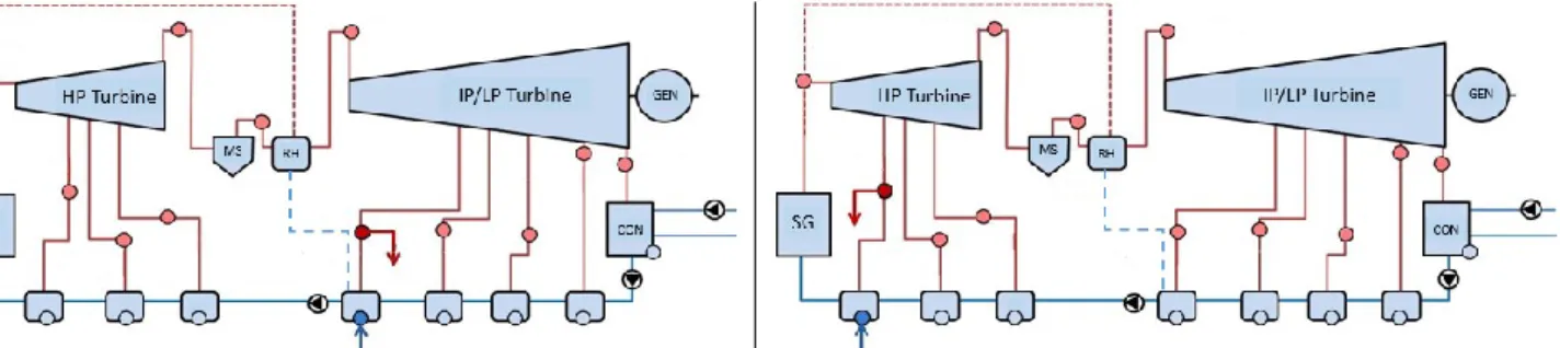
Three cogeneration cases have been calculated to provide different types of temperature grades, by so covering a range of possible cogeneration needs. Inline, steam extraction lines have been implemented on the cycle as follow: at steam generators outlet (HT-grade case), at turbine high pressure group outlet
(MT-grade case) and finally at first extraction line of the turbine low pressure group (LT-(MT-grade case).
As reported in Figure 7, in each case, the extracted steam flow is condensed and then returned to the cycle. Hence, only the latent heat of condensation is considered as valuable for cogeneration, which actually corresponds to the main part of the available power of a steam flow. This allows also gaining genericity since thermal pinch with the process is disregarded. Steam thermodynamic characteristics are reported in Table 4 for each case.
9 Table 4. Thermodynamic characteristics of the steam used for cogeneration
Case Pressure, bar Temperature, °C Thermodynamic title
HT-grade 69.50 285.3 0.995
MT-grade 10.74 183.0 0.860
LT-grade 2.97 146.5 Superheated (>1)
HT-grade MT-grade
LT-grade
Figure 7. Steam extraction lines implemented for cogeneration and corresponding condensers (red boxes), THERMOFLEX
On the basis of these three configurations, performances of the cycle have been calculated with THERMOFLEX and CYCLOP (which respective methodologies have been summarized in section 2), while varying thermal power load which is made available for cogeneration, up to 20% of SGs power input. It is worth noticing that to achieve this load, extraction lines that are virtually added in Figure 7 for MT-grade and LT-grade cases, offer extra capacity compare to powers of the reference case that are reinjected through
souti4 and souti6 lines to heat-up the feed-water line (see Figure 4). Indeed, these lines transfer less than 10%
each of the SGs power and therefore would not suit the 20% load target.
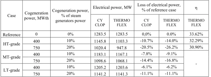
3.2 Cycle performance results
10 Table 5 summarizes cycle performances in terms of electrical power to the grid. Additionally, cycle electrical efficiency defined as the ratio of electrical power provided to the grid by steam generators power minus cogeneration power, is reported. Note that is only calculated for HT-grade case where it makes sense for comparison to reference case. Indeed, high steam temperature grade from the steam generators is used directly for cogeneration i.e. without going through, neither high nor low-pressure turbine groups for this lonely case. Inline, deviation of from reference case shows the rise of the thermodynamic irreversibilities for electrical production due to turbine part-load operation that is carried out for cogeneration purpose.
Table 5. Cycle performances under part-load operation, CYCLOP & THERMOFLEX
Case power, MWth Cogeneration Cogeneration power, % of steam generators power
Electrical power, MW Loss of electrical power, % of reference case
CY CLOP THERMO FLEX CY CLOP THERMO FLEX THERMO FLEX Reference 0 0% 1283.5 1283.5 0,0% 0.0% 33.62% HT-grade 400 10% 1145.8 1103.3 -10.7% -14.0% 32.29% 750 20% 1020.4 947.8 -20.5% -26.2% 30.90% MT-grade 400 10% 1183.1 1167.1 -7.8% -9.1% - 750 20% 1098.6 1068.1 -14.4% -16.8% LT-grade 400 10% 1205.2 1203.6 -6.1% -6.2% 750 20% 1141.2 1141.3 -11.1% -11.1%
Figure 8 reports drops of electrical power and from reference values according to the different cogeneration scenarios.
Figure 8. Drop of electrical power (left) and cycle efficiency (right) from reference case as a function of cogeneration thermal power, CYCLOP & THERMOFLEX
From Table 5 and Figure 8, it comes out that:
– Deviation of the results between THERMOFLEX - which takes into account irreversibility change due to part-load operation - and CYCLOP, which considers only on-design components performance, are insignificant for LT-grade case. Indeed, in Table 5, losses of electrical power relative to reference case only differ from a tenth so that deviation of electrical powers provided to the grid, is less than 0.15% between the codes. This lesson is in line with the usual engineering
-10% -9% -8% -7% -6% -5% -4% -3% -2% -1% 0% 1% 0% 5% 10% 15% 20% 25% Electr ical p ow er to th e gr id , % o f ref er en ce ca se
Thermal power provided to cogeneration, % of steam generator power
HT-grade, Thermoflex HT-grade, Cyclop MT-grade, Thermoflex MT-grade, Cyclop LT-grade, Thermoflex LT-grade, Cyclop -3,0% -2,5% -2,0% -1,5% -1,0% -0,5% 0,0% 0% 5% 10% 15% 20% 25% D
,
po in tsThermal power provided to cogeneration, % of steam generator power
11 approach not considering off-design aspects for low temperature grade cogeneration, as reported in section 1. Another way to analyse this consistency addresses new systems, which would open engineering possibilities for a multi-objectives thermodynamic optimization regarding cycle dual operating modes (100% electrical duty and low temperature grade cogeneration). The present results confirm indeed that part-load operation of a cycle originally optimized for a 100% electrical duty (as this is the case with the reference design) shows poor deviation of the performance (THERMOFLEX) compare to an on-design cogenerating cycle (CYCLOP). Hence, multi-objectives thermodynamic optimizations considering dual modes would very likely result in a design similar to original one’s which targets a 100% electrical duty.
– On the other hand, as far as cogeneration with higher temperature grade is addressed, impact of irreversibility change due to part-load operation rises significantly. As such, for HT-grade case reported in Figure 8, CYCLOP calculation of the electrical power provided to the grid at a 20% load, is overestimated by 72.6 MW (7.6% of the delivered electrical power). One can additionally note in Figure 1-right that (Abdoelatef, Field, & Lee, 2015) considered cogeneration performance while extracting steam from the high pressure group. According to the results reported in Figure 8, such an investigation should have required, to gain accuracy, to address part load irreversibilities, which is not the case with the DETOP IAEA software which was applied.
– Drop in cycle electrical efficiency, D, is about 2.7 points for HT-grade case at a 20% cogeneration load, as reported in Figure 8. Extrapolation of the preceding results to a 50% cogeneration load, according to the observed linear trend, would rise D to 6.9 points. This highlights that advanced temperature grades cogeneration could offer significant margin for a multi-objectives thermodynamic optimization, as far as new PCSs design could be considered.
– Results from THERMOFLEX in Figure 8 map electrical to thermal flexibility performances that can be expected in the investigated range, by using a Rankine cycle exemplary from PWR PCSs. Inline, the following relationships can be defined (electrical power drop, 𝑃𝑜𝑤𝑒𝑟𝐷𝑟𝑜𝑝, and cogeneration power load, 𝐶𝑜𝑔𝐿𝑜𝑎𝑑, being expressed respectively as a fraction of electrical and SGs thermal powers):
For high temperature grade steam:
𝑃𝑜𝑤𝑒𝑟𝐷𝑟𝑜𝑝 = −1.3312 × 𝐶𝑜𝑔𝐿𝑜𝑎𝑑 [1] For medium temperature grade steam:
𝑃𝑜𝑤𝑒𝑟𝐷𝑟𝑜𝑝 = −0.8540 × 𝐶𝑜𝑔𝐿𝑜𝑎𝑑 [2] For low temperature grade steam:
𝑃𝑜𝑤𝑒𝑟𝐷𝑟𝑜𝑝 = −0.5646 × 𝐶𝑜𝑔𝐿𝑜𝑎𝑑 [3] With: 𝐶𝑜𝑔𝐿𝑜𝑎𝑑 ≤ 20%
4. Analysis of turbine part-load mechanisms with THERMOFLEX
This section analyses with THERMOFLEX, turbine part-load operation mechanisms which are responsible for thermodynamic irreversibilities change. Inline, Tables 6 and 7 summarize performances of high and low pressure turbine groups for HT-grade and LT-grade cases and corresponding flow-sheets are reported in the Appendix. Both cases have been indeed reported in section 3 as respectively deviating very much from an on-design cogeneration calculation approach (by showing a large discrepancy compare to CYCLOP results), or at contrary as providing very close results.
From these tables, it comes out that:
– Turbine operation at part-load, that is modelled in THERMOFLEX by application of the Stodola ellipse law while considering constant outlet pressure as boundary condition (cycle heat sink temperature is indeed supposed as unchanged), results in a shift of expansion lines to reduced pressure domains, as reported in Figure 9.
– This point has a main consequence: pressure ratios are reduced for both turbine groups so that steam admission governing which is done through valves throttling (as reported in section 2.2), provides additional irreversibility at part-load (isenthalpic, Joule-Thomson, expansion).
12 – On the other hand, isentropic efficiency of each turbine group does not show significant deviation (less than 0.5 point throughout the reported cases) or even increases (see low pressure turbine group of the HT-grade case). While many details about THERMOFLEX turbine modelling are not available, this could be however analysed as follows: among the three main contributions to turbine losses reported in section 2.2, rise of irreversibilities due to deviations from design values of stage mass flow coefficient and exhaust velocity, are actually more or less counterbalanced by the lowering of the last source of irreversibility which is connected to steam moisture content. Indeed, due to the reported lowering of the pressures, steam expands within drier condition, hence more efficiently.
– It comes out from these tables, by comparing evolution of efficiencies with and without isenthalpic valves, that the latter throttlings are responsible for the main part of irreversibility increase at part-load.
– Regarding the 20% cogeneration load, the efficiency drop (taking into account throttling) is maximal for the high pressure turbine group for HT-grade case and is as high as 11 points. Instead, for LT-grade case, it is the low pressure group efficiency drop which is maximal but the latter rates only about 1 point. Shift of expansion lines to a lower pressure domain is indeed much lighter for
LT-grade case so that connected throttling losses: Table 5 reports consistently that drop of
mechanical work to be performed to achieve the targeted 20% cogeneration load, is roughly 2.3 times less for LT-grade case than for HT-grade case.
– Differences which were reported, explain why an on-design approach for cogeneration, as performed with CYCLOP which is blind to part-load valve throttling aspect, is respectively irrelevant for calculating cycle efficiency of HT-grade case, and provides instead rather accurate results for LT-grade case. However, it has been outlined that such a consistency is actually also partly driven by counter-balance of some opposite irreversibility changes within the turbine.
13 Table 6. High and low pressure turbine groups performance at part-load, HT-grade case, THERMOFLEX
Turbine group High pressure group Low pressure group Cogeneration load, % of steam
generators power 0 10 20 0 10 20 Governing throttling valve Inlet Pressure, bar 69.50 10.12 10.02 9.93 Steam thermodynamic quality 0.995 Superheated Enthalpy, kJ/kg 2766.13 2979.70 2981.74 2985.38
Pressure ratio (not providing work,
see isenthalpic transformation ) 1.053 1.210 1.390 1.001 1.113 1.233
Turbine group Inlet Pressure, bar 66.02 57.45 49.99 10.11 9.09 8.21 Steam thermodynamic quality 0.993 0.987 0.983 Superheated Enthalpy, kJ/kg 2766.13 2979.70 2981.74 2985.38 Outlet Pressure, bar 10.742 10.562 10.408 0.062 Steam thermodynamic quality 0.860 0.869 0.878 0.8735 0.8734 0.8734 Enthalpy, kJ/kg 2499.56 2515.63 2533.31 2262.20 2275.68 2289.75 Pressure ratio 6.146 5.439 4.803 163.065 146.662 132.376 Steam work, MW 493.7 406.16 330.47 879.08 779.44 693.75 Isentropic efficiency, % 82.65% 82.64% 82.28% 87.15% 87.23% 87.31% Throttling valve +
14 Table 7. High and low pressure turbine groups performance at part-load, LT-grade case, THERMOFLEX
Turbine group High pressure group Low pressure group Cogeneration load, % of steam
generators power 0 10 20 0 10 20 Governing throttling valve Inlet Pressure, bar 69.50 10.12 10.10 10.10 Steam thermodynamic quality 0.995 Superheated Enthalpy, kJ/kg 2766.13 2979.70 2981.74 2985.38
Pressure ratio (not providing work, see isenthalpic
transformation ) 1.053 1.053 1.052 1.001 1.022 1.043 Turbine group Inlet Pressure, bar 66.02 65.99 66.04 10.11 9.89 9.69 Steam thermodynamic quality 0.9925 0.9925 0.9925 Superheated Enthalpy, kJ/kg 2766.13 2979.70 2977.74 2978.18 Outlet Pressure, bar 10.742 10.719 10.710 0.062 Steam thermodynamic quality 0.8601 0.8601 0.8600 0.8734 0.8748 0.8767 Enthalpy, kJ/kg 2499.56 2499.39 2499.20 2262.20 2265.61 2270.19 Pressure ratio 6.146 6.156 6.167 163.065 159.472 156.303 Steam work, MW 493.7 494.09 494.81 879.08 795.82 730.34 Isentropic efficiency, % 82.65% 82.63% 82.62% 87.15% 86.92% 86.69% Throttling valve +
turbine group Isentropic efficiency, % 80.64% 80.60% 80.63% 87.14% 86.60% 86.08%
reference case HT-grade – 20% load
Figure 9. Shift of the expansion lines (for high and low pressure groups) in the h – s plan from reference case to part-load operation, THERMOFLEX
A peculiar consequence of the turbine expansion lines shift to a lower pressure domain, is that for LT-grade case, temperature provided for cogeneration is actually decreasing from 146 down to 121°C, as reported in Figure 10. This trend, to which an on-design approach is blind, could have serious consequence for PCS coupling with a cogeneration process at large load and should be as such taken into account. Complementarily, it has to be noticed that:
15 – This aspect is not engaged for HT-grade case, since pressure, hence temperature are the ones at the SGs outlets, which thermal hydraulic operation is supposed to be unchanged and set consistently with their coupling with primary circuit of the nuclear vessel.
– If alternatively to the implementation of a steam extraction line as reported in Figure 7 LT-grade case, one takes advantage of the heat reinjected in the feed-water line through echangR3 of souti3 line (Figure 4), this issue is no longer raised but thermal power which is made available for cogeneration is limited by the line design capacity, which is roughly about 6% of SGs power. The reason for unchanged temperature if one uses souti6 is simply that turbine pressures quite does not change since flow rate through the turbine line does not also. At contrary for LT-grade case, steam flowrate which is derivated for cogeneration purpose, is extracted from turbine expansion line, by so changing turbine operation.
Figure 10. Evolution of steam temperature extracted from the cycle as a function of cogeneration thermal load, LT-grade case.
5. Conclusions
The present work has been carried out in the generalized context of a growing base power capacity of carbon free - but intermittent - renewable energies. This trend could make electrical and thermal power mix possibility, a relevant technical flexibility and economical alternate for nuclear power plants, instead of systematically accommodating grid load-following through nuclear core power change. Inline, the work has been devoted to map a Rankine PCS performance (typical from Gen2 PWRs) under cogeneration, by considering extended thermal load and temperature grade compare to common cogeneration applications such as district heating or water desalinisation. On this basis, electrical power to the grid has been mapped as a function of cogeneration thermal power so that first guidelines about the mix possibility for such a design, which could be actually seen as exemplary of current PWRs PCSs, is provided.
A peculiar point of the study has been to perform cogeneration calculations by considering or not thermodynamic irreversibilities change arising from cycle operation under electrical part-load. It comes out from the present work that, as far as medium and high temperature grades cogeneration are addressed, part-load effects should be considered. Indeed, for a cogeneration part-load corresponding to 20% of SGs power, cycle electrical efficiency drops from 2.7 points while extrapolation of this result to a 50% load would significantly rise the loss to 6.9 points. Two conclusions could be provided: methodologically (the lesson is got on a Gen2 PWR PCS design but can be extended to advance Rankine PCSs, eg. Gen3+), an on-design approach for cogeneration performance calculation, such as relevantly applied in the literature for low temperature grade cogeneration, is instead poorly relevant for higher temperature grades. Second, in the frame of new PCSs, it should be relevant to perform a multi-objectives optimization of the design, targeting dual operating modes (electrical and thermal).
Finally, turbine part-load mechanisms and connected thermodynamics irreversibilities, have been analysed. It comes out that isenthalpic throttling valves which govern steam admission in turbine groups, play a key role while degradation of turbine efficiency remain low in the investigated range; turbine expansion lines are indeed shifted to lower pressures, lowering turbine losses contribution by steam moisture content.
100,0 105,0 110,0 115,0 120,0 125,0 130,0 135,0 140,0 145,0 150,0 0% 5% 10% 15% 20% 25%
16 This work paves the way to next investigation of an extended range for electrical and thermal powers mix, which could be relevantly associated to an exergetic analysis of the system and should include a modelling of SGs operation.
6. Acknowledgements
Authors are grateful to Dr. S. Dardour from Atomic International Energy Agency and Pf. H. Grard from French National Institute for Nuclear Science and Technology, for informative exchanges. CEA/DEN/GEN2-3 program and ISYMAR project that supported the present work, are also acknowledged.
17
References
Abdoelatef, M., Field, R., & Lee, Y.-K. (2015). Thermodynamic Evaluation of Coupling APR1400 with a Thermal Desalination Plant. International Journal of Chemical and Molecular Engineering, Volume 9.
Astvatsaturova, A., Zorin, V., & Trukhnii, A. (2015). Assessment of Steam Work Efficiency as Applied to a Turbine Being Designed. Thermal Engineering, 26–33.
Audoly, R., Vogt-Schilb, A., Guivarch, C., & Pfeiffer, A. (2018). Pathways toward zero-carbon electricity required for climate stabilization. Applied Energy, 884-901.
Baumann, K. (1912). Recent developments in steam turbine practice. Journal of the Institution of Electrical
Engineers, 768-842.
Cany, C., Mansilla, C., G, & da Costa, P. (2018). Nuclear power supply: Going against the misconceptions. Evidence of nuclear flexibility from the French experience. Energy, 289-296.
Cooke, D. (1985). On Prediction of Off-Design Multistage Turbine Pressures by Stodola's Ellipse.
Transactions of the ASME, 596-606.
Floyd, J., Alpy, N., Moisseytsev, A., Rodriguez, G., Sienicki, J., & Avakian, G. (2013). A numerical investigation of the sCO2 recompression cycle off-design behaviour, coupled to a sodium cooled fast reactor, for seasonal variation in the heat sink temperature. Nuclear Engineering and Design, Volume 260, 78-92.
Geffraye, G., Antoni, O., Farvacque, M., Kadri, D., Lavialle, G., Rameau, B., & Ruby, A. (2011). CATHARE 2 V2.5 2: A single version for various applications. Nuclear Engineering and Design, 4456-4463. Gen-4. (2019). Retrieved from https://www.gen-4.org/gif/
Grard, H. (2014). Physique, fonctionnement et sûreté des REP. Les Ulis: EDP sciences.
Haubensack, D., Thévenot, C., & Dumaz, P. (2004). The Copernic/Cyclop Computer Tool: Pre-conceptual Design of Generation 4 Nuclear Systems. 2004 Conference on High Temperature Reactors. Beijing, China.
Hittner, D., Bogusch, E., Fütterer, M., de Groot, S., & Ruer, J. (2011). High and very high temperature reactor research for multipurpose energy. Nuclear Engineering and Design, 3490-3504.
Hittner, D., Lommers, L., & Shahrokhi, F. (2012). R&D needs for near-term HTRs. Nuclear Engineering
and Design, 131-138.
International Atomic Energy Agency. (2007). Advanced Applications of Water, IAEA-TECDOC-1584. Vienna, Austria: ISBN 978–92–0–105808–9.
International Atomic Energy Agency. (2017). Opportunities for cogeneration with Nuclear Energy. Vienna, Austria: IAEA NUCLEAR ENERGY SERIES No. NP-T-4.1.
Irena. (2018). Renewable capacity statistics 2018. Abu Dhabi: International Renewable Energy Agency. Retrieved from https://www.irena.org/publications/2018/Mar/Renewable-Capacity-Statistics-2018 I-Tésé. (2018). Energy Handbook. Gif sur Yvette: Commissariat à l'énergie atomique et aux énergies
alternatives. Retrieved from http://www.cea.fr/multimedia/Pages/editions/ouvrages/memento-sur-energie.aspx
Jasserand, F., & Devezeaux de Lavergne, J. (2016). Initial economic appraisal of nuclear district heating in France. EPJ Nuclear Sci. Technol, 2-11, Volume 39.
Le Pierres, N., Luo, L., Berthiaud, J., & Mazet, N. (2009). Heat transportation from the Bugey power plant.
International Jopurnal of Energy Research, 135-143.
Leurent, M., Jasserand, F., Locatelli, G., Palm, J., Rama, M., & Trianni, A. (2017). Driving forces and obstacles to nuclear cogeneration in Europe: Lessons. Energy Policy, 138-150.
Lokhov, A. (2011). Load-following with nuclear power plants. NEA updates, NEA News. Retrieved from https://www.oecd-nea.org/nea-news/2011/29-2/nea-news-29-2-load-following-e.pdf
18 Manente, G., Rech, S., & Lazzaretto, A. (2016). Optimum choice and placement of concentrating solar power
technologies in integrated solar combined cycle systems. Renewable Energy, 172e189.
Nelder, J., & Mead, R. (1965). A Simplex Method for Function Minimization. The Computer Journal,, 308-313, Volume 7.
Pham, H., Alpy, N., Ferasse, J., Boutin, O., Quenaut, J., Tothill, M., . . . Saez, M. (2015). Mapping of the thermodynamic performance of the supercritical CO2cycle and optimisation for a small modular reactor and a sodium-cooled fast reactor. Energy, 412-424.
Popov, D., & Borissova, A. (2017). Innovative configuration of a hybrid nuclear-solar tower power plant.
Energy, 736-746.
Safa, H. (2012). Heat recovery from nuclear power plants. Electrical Power and Energy Systems, 553-559. Sanchez-Cervera , I., Kavvadias, K., & Khamis, I. (2013). DE-TOP: A new IAEA tool for the thermodynamic
evaluation of nuclear desalination. Desalination, 103-109.
Sheffield, J., Martin, B., & Folkson, R. (2014). Electricity and hydrogen as energy vectors for transportation vehicles. In Alternative Fuels and Advanced Vehicle Technologies for Improved Environmental
Performance (pp. 117-137). Elsevier.
Thermoflow. (2019). Retrieved from https://www.thermoflow.com/
Thern, M., Jordal, K., & Genrup, M. (2014). Temporary CO2 capture shut down: Implications on low pressure steam turbine design and efficiency. Energy Procedia, pp. 14-23. doi:10.1016/j.egypro.2014.07.002
19 APPENDIX
HT-grade case, 20% load, THERMOFLEX