HAL Id: in2p3-00013993
http://hal.in2p3.fr/in2p3-00013993
Submitted on 16 Sep 2003
HAL is a multi-disciplinary open access archive for the deposit and dissemination of sci-entific research documents, whether they are pub-lished or not. The documents may come from teaching and research institutions in France or abroad, or from public or private research centers.
L’archive ouverte pluridisciplinaire HAL, est destinée au dépôt et à la diffusion de documents scientifiques de niveau recherche, publiés ou non, émanant des établissements d’enseignement et de recherche français ou étrangers, des laboratoires publics ou privés.
The gravitational wave detector VIRGO
R. Flaminio, F. Bellachia, D. Boget, D. Buskulic, François Chollet, P.Y.
David, D. Dufournaud, L. Fournier, L. Giacobone, Christian Girard, et al.
To cite this version:
R. Flaminio, F. Bellachia, D. Boget, D. Buskulic, François Chollet, et al.. The gravitational wave detector VIRGO. Advanced ICFA Beam Dynamics Workshop on Nanometre Size Colliding Beams 26 Nanobeam 2002, Sep 2002, Lausanne, Switzerland. pp.7-13. �in2p3-00013993�
LAPP-EXP 2002-16
December 2002
THE GRAVITATIONAL WAVE DETECTOR VIRGO
Raffaele Flaminio
on behalf of the Virgo Collaboration
LAPP-IN2P3-CNRS
9 chemin de Bellevue - BP. 110, F-74941 Annecy-le-Vieux Cedex
THE GRAVITATIONAL WAVE DETECTOR VIRGO
Presented by
Raffaele Flaminio
on behalf of the Virgo Collaboration
F.Bellachia, D.Boget, D.Buskulic, F.Chollet, P.Y.David, D.Dufournaud, R.Flaminio, L.Fournier,
L.Giacobone, C.Girard, R.Hermel, A.Kaczmarska, R.Kassi, B.Lieunard, F. Marion, A.Masserot,
L.Massonnet, F.Moreau, B.Mours, P.Mugnier, J.Ramonet, E.Tournefier, D.Verkind, O.Veziant,
S.Vilalte, M.Yvert
Laboratoire d’Annecy-le-Vieux de Physique des Particules, Annecy-le-Vieux, France
G. Ballardin, A.Bozzi, C.Bourgoin, S.Cortese, D.Enard, P.La Penna, M.Loupias, S.Mataguez,
A.Paoli, A.Pasqualetti, P.Popolizio, F.Richard, R.Taddei, J. M.Teuler, Z.Zhang
European Gravitational Observatory, Cascina, Italy
L.Bracci, G.Calamai, G.Conforto, E.Cuoco, P.Dominaci, L.Fabbroni, G.Guidi, G.Losurdo,
F.Martelli, M.Mazzoni, M.Ripepe, R.Stanga, F.Vetrano, A.Viceré
INFN and Universita di Firenze/Urbino, Firenze, Italy
D.Babusci, F.Honglie, G. Giordano, M. Iannarelli, E. Turri
Laboratori Nazionali INFN di Frascati, Frascati, Italy
D.Forest, P.Ganau, B.Lagrange, J.M.Mackowski, C.Michel, J.L.Montorio, N.Morgado, L.Pinard,
A.Remillieux
Institut de Physique Nucleaire de Lyon, Lyon, France
F.Acernese, F.Barone, E.Calloni, S.Cavaliere, M.De Rosa, R.De Rosa, L.Di Fiore, A.Eleuteri,
G.Evangelista, L.Milano, K.Qipiani, G.Russo, S.Solimeno, M.Varvella
INFN Napoli, Universita di Napoli ‘Federico II’ and Universita di Salerno, Napoli, Italy
F.Bondu, A.Brillet, J.Cachenaut, E.Chassande-Mottin, F.Cleva, T.Cokelaer, J. P.Coulon,
J.D.Fournier, H.Heitmann, J.M.Innocent, C.N.Man, F.Mornet, J.Pacheco, T.Regimbau,
J.P.Scheidecker, H.Trinquet, P.Tourrenc, J.Y.Vinet
Observatoire de la Cote d’Azur, Nice, France
N.Arnaud, C.Arnault, M.Barsuglia, J.L.Beney, R.Bilhaut, M.A.Bizouard, V.Brisson, P.Canitrot,
F.Cavalier, R.Chiche, S.Cuzon, M.Davier, M.Dehamme, C.Eder, M.Gaspard, P.Hello, P.Heusse,
E.Jules, O.Lodygensky, B.Mansoux, J.C.Marrucho, P.Marin, M.Mencik, E.Edward, T.Pradier,
A.Reboux, P.Rivoirard, M.Taurina
Laboratoire de l’Accelerateur Lineaire, Orsay, France
C.Boccara, M.Leliboux, V.Loriette, V.Reita, J.P.Roger
ESPCI, Paris, France
P.Amico, C.Cattuto, L.Gammaitoni, F.Marchesoni, M.Punturo, H. Helios
INFN and Universita di Perugia, Perugia, Italy
S.Braccini, C.Bradaschia, R.Cavalieri, R.Cecchi, G.Cella, V.Dattilo, A.Di Virgilio, I.Ferrante,
F.Fidecaro, F.Frasconi, G. Gennaro, A.Giazotto, L.Holloway, T.Lomtadze, E.Majorana, F.Nenci,
L.Nicolosi, F.Paoletti, R.Passaquieti, D.Passuello, R.Poggiani
INFN and Universita di Pisa, Pisa, Italy
R.Bizzarri, S.Frasca, C.Palomba, M.Perciballi, P.Puppo, P.Rapagnani, F.Ricci
INFN and Universita di Roma ‘La Sapienza’, Roma, Italy
Abstract
VIRGO is a gravitational wave detector based on a Michelson interferometer with 3 km long arms. The aim of the experiment is the first detection of gravitational waves emitted by compact stellar objects such as neutron stars, black holes or supernova. The detector is being built near Pisa (Italy) by a French–Italian collaboration funded by INFN in Italy and CNRS in France. The test of the central part of the interferometer have been performed successfully this year. Civil engineering has also been completed this year and the detector final assembly will be finished early next year. The main scientific goals and detector issues are introduced. Some of the control and stabilization systems used to operate the interferometer are also discussed. Recent results and present status are presented.
1 SCIENTIFIC MOTIVATIONS
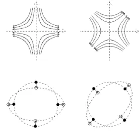
Gravitational waves [1] are predicted by Einstein general relativity theory. According to Einstein theory, the gravitational force is a manifestation of space-time curvature. Any mass curves the space-time geometry around itself and, as a consequence, it curves the trajectory of a free falling test mass passing nearby. If this same mass starts oscillating the space-time curvature will also start oscillating and this oscillation will propagate across space-time at the speed of light as a wave propagating on a water surface. These small propagating perturbations of the space-time metric are gravitational waves. Their effect is to change the distance between two free falling masses and a detailed analysis of Einstein equations shows that they are spin 2 waves. As a consequence if a gravitational wave travels across a set of masses placed on a circle, the circle will be transformed in an ellipse with its axis pointing in the direction of the wave polarization (see Fig. 1). If L is the circle diameter, it will undergo a change h·L/2 where h<<1 is the gravitational wave amplitude.
Any mass produces gravitational waves with amplitude h proportional to the second derivative of its quadrupole moment Q:
d
Q
c
G
2
h
≈
4&
&
where d is the source distance. The coupling factor being a relatively small number (G/c4 = 8⋅10-45 m/J) it is not possible to produce detectable gravitational waves on earth. On the other hand several astrophysical objects are expected to be significant sources of gravitational waves [2].
The binary system PRS 1913+16 [3], discovered by Taylor and Hulse in 1974, has provided the first indirect
evidence of a process involving gravitational waves emission. This is a binary system formed by two neutron stars (one being a radio pulsar) whose period is progressively decreasing due to the energy lost via the gravitational wave emission. The agreement between data and theoretical prediction is excellent. As the binary orbital period progressively decreases, the two stars get closer and closer until the moment they will coalesce and merge in a single object. This binaries stars are known as coalescing binaries [2].
The gravitational wave produced by a coalescing binary during the last few minutes spans the audio band up to around 1 kHz and it should be detectable up to distances of the order of 100 Mpc. Few of these binary systems have been detected by radio astronomer in our galaxy and a few coalescences are expected to occur each year at distances d < 200 Mpc. The detection of these signals will provide new data on the gravitational force in strong field conditions, on the matter equation of state at the densities typical of neutron stars and it will furnish a new kind of standard candle. Similar and even more interesting binary systems are expected to be composed by black holes.
Gravitational waves are expected to be emitted by other astrophysical sources such as rotating neutron stars, stellar core collapse, black hole formation and the big bang [2]. The detection of these signals would allow to get new fundamental data on the gravitational interaction and to investigate a wide variety of topics ranging from the neutrino mass and black holes properties up to physics laws at the Planck scale.
Figure 1: Lines of force associated with the two possible gravitational wave polarisation states (top) and their effect
2 GRAVITATIONAL WAVE DETECTION
In order to detect a few events per year one requires to have a sensitivity in h of the order of h~10-21 or equivalently to measure displacements of the order of 10-18 m between two masses few km apart.
The form of the metric perturbation induced by a gravitational wave is such that a Michelson type interferometer is the ideal instrument for its detection [4]. Provided that the interferometer mirrors are properly suspended (and so free to move above the pendulum resonance), as a gravitational wave passes through the interferometer plane one arm gets longer while the other gets shorter. This induced a change in the interference pattern which is detected by means of a continuous monitoring of the light which leaves the interferometer output port. The change in the interference pattern is determined by the phase shift between the two light beams travelling in the two arms of the interferometer: dφ=4πhL/λ where L is the arm length and λ the light wavelength. From the uncertainty relation the accuracy in the measurement of such a phase shift is limited by the inverse of the fluctuation dNγ in the number of photons Nγ impinging on the beam splitter. Since dNγ=√Nγ the minimum detectable gravitational wave should have a spectral amplitude
h
~
:P
h
2
L
4
h
~
ν
π
λ
>
where P is the light power sent into the interferometer and hν the energy of a single photon. This is known as the photon shot noise limit. In order to achieve a spectral sensitivity of the order of 3·10-23 Hz-1/2 (or equivalently a sensitivity of the order of 10-21 for a 1ms long pulse signal) it is necessary to have e.g. arms length L~100 km and a laser power P~1 kW.
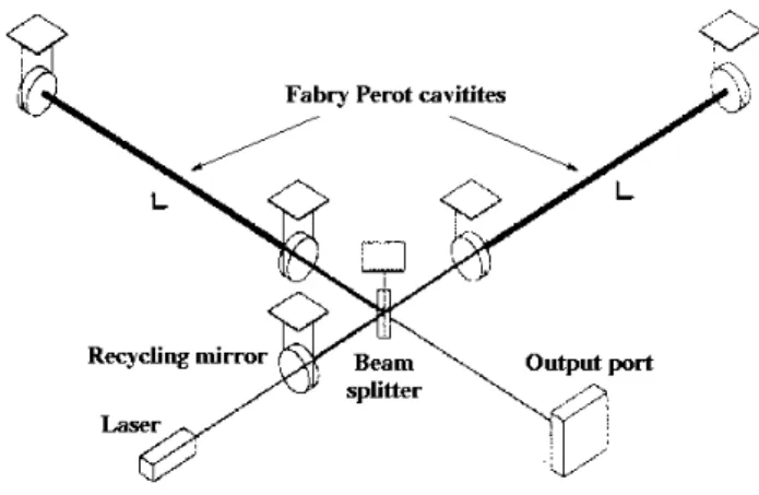
It is possible to achieve an equivalent length of 100 km by inserting a Fabry-Perot cavity in each of the two arms of the interferometer [5] (see Fig. 2). By means of these cavities the gravitational wave signal is integrated over a time τ equal to the average time spent by the photons in the cavity. As a consequence the phase shift induced by the gravitational wave is multiplied by a factor roughly equal to the Fabry-Perot finesse. By means of a 3 km long cavity having a finesse of 50 one gets an equivalent length of about 100 km. It is worth mentioning the integration of the signal with Fabry-Perot cavity will tend to reduce the sensitivity to gravitational waves with periods T < τ .i.e. for frequencies above f ~ 1kHz.
In order to minimize the detector sensitivity to all type common mode noise (typically due to laser fluctuations) it is better to set and keep the interferometer arm length difference such to have destructive interference at the interferometer output port. In this conditions the large majority of the light is reflected back toward the laser. By means of an additional mirror placed between the laser and the interferometer (see Fig. 2) it is possible to recycle this light [5]. An additional cavity is formed, having this additional mirror (called the recycling mirror) as input
mirror and the interferometer as second reflector. By properly setting this cavity at resonance with respect to the laser wavelength it is possible to enhance the power impinging on the beam splitter by about two orders of magnitude and to reach the required 1 kW with a laser delivering ‘only’ 10-20 W.
Figure 2: A gravitational wave detector based on a laser interferometer with Fabry-Perot cavities in the arms and a
recycling mirror for light power recyhcling The required displacement sensitivity is about ten orders of magnitude smaller than the natural earth seismic vibration at 10 Hz. As a consequence it is necessary to have all the mirrors of the interferometer isolated by means of an excellent seismic isolation system. Even if only horizontal mirrors motions are measured, due to mechanical coupling in the suspension and to the earth curvature, it is necessary to have an excellent seismic isolation also in the vertical direction. To this purpose the mirrors are suspended to multi stages pendulums made by a cascade of springs providing the vertical attenuation [6]. Several other sources of noise may affect the sensitivity of such a detector. One of these is the thermal noise inside the mirror and inside the suspension wires which excites the mirror internal resonance modes as well as the pendulum and wires resonances modes [7]. The use of high quality material with low internal dissipation allows to reduce this noise below the required sensitivity, but it remains one of the major limitation to the performance of these detectors [6,7]. Acoustic noise, air index of refraction fluctuations and mirrors pollution are also sources of sensitivity degradation and they all require to keep the whole interferometer under vacuum. Finally electronics noise affecting the laser system, the photodiodes readout system and the various control loops is a potential source of noise that need to be careful analysed and reduced to extremely low levels.
3 THE VIRGO DESIGN
3.1 The interferometer design
The Virgo detector [8] is based on a laser interferometer with 3 km long arms (see Fig. 3). The detector is being built near Pisa (Italy) by a French-Italian collaboration funded by INFN in Italy and CNRS in France. The Virgo collaboration includes about 170 people from 11 different institutions.
Figure 3: Scheme of the Virgo interferometer. The part contained in the inner box is the central interferometer The interferometer is illuminated by means of a single frequency Nd:YAG laser delivering about 20 W. Each arm is a 3 km long Fabry-Perot cavity having a finesse of 50. The recycling technique is used to enhance the power impinging on the beam splitter by about two orders of magnitude. In order to achieve such a recycling factor the mirrors are made of high quality silica, properly polished and coated in order to keep diffusion and absorption losses at a level of few ppm. For similar reason the surface quality should be at the level of λ/100. In order to deal with a few cm diameter beam and to keep thermal noise as low as possible the mirror are relatively large (35 cm in diameter and 10 cm thick) and massive (about 20 kg). Special technology has been developed in order to meet and check the optical quality on such large mirrors.
Before entering the interferometer the beam is spatially filtered by means of a 150 m triangular cavity known as input mode-cleaner [9] (see Fig. 3). Even if the main goal is to filter all the vibrations in the beam position and direction (beam jitter), the cavity can also be used for laser frequency stabilization purposes.
At the interferometer output the light beam is detected by an array of InGaAs photodiodes with quantum efficiency larger than 90% [10]. Before being detected the light is transmitted trough an output mode-cleaner which filters all spurious light diffused by the interferometer optics. This is a short (4 cm) monolithic cavity made of a piece of silica properly polished and coated [10].
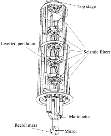
All the mirrors are suspended to seismic isolators called super-attenuator [11]. These suspensions are based on a
six stages pendulum suspended to a pre-isolator constituted by a 6 m tall inverted pendulum [12] (see Fig. 4). Each stage of the multi-pendulum is a seismic filter based on cantilever springs and magnetic anti-springs providing the required vertical attenuation [13]. All the super-attenuator internal modes are kept below 4 Hz and the attenuation at this frequency is about 1010.
Figure 4: View of the seismic isolator
The mirrors are suspended by means of four thin wires (200 µm in diameter) to the last stage of the suspension. This is a special stage, called ‘marionetta’ [14], to which four magnets are attached. By means of four coils attached to the last seismic filter it is possible to rotate the ‘marionetta’ (and so the mirror) both around a vertical axis and around an horizontal axis.
Also suspended to the ‘marionetta’, is an additional mass, called reference mass (or recoil mass), which is placed ‘around’ the mirror in a way that its centre of mass coincides with the mirror one. By means of four coils attached to the reference mass it is possible to apply forces on four small magnets attached to the mirror and so to produce small displacements (or rotations) of the latter [14].
All the mirrors and their seismic isolators are inside large vacuum chambers at about 10-9 mBar. All along the arms the light travel inside a 1.2 m diameter tube also kept under ultra high vacuum.
3.2 The interferometer control system
The super-attenuators provides an excellent seismic isolation above 4 Hz. At lower frequencies the isolators
internal resonances produce an amplification of seismic noise. Displacements in the range of 10-100 µm may affect the mirrors position in the 10 s to 100 s time scale due to the excitation of the first fundamental resonance of the isolator. Even larger drifts may affect the arm length due the earth tidal strain. In order to maintain the interferometer aligned and to keep it locked to the required interference conditions several control systems working in cascade are used.
First of all the suspension internal resonances are damped by means of inertial sensors (accelerometers) and displacement sensors (LVDT) mounted at the top of the inverted pendulum and sensing the suspension’s low frequency oscillations [15]. LVDT’s and accelerometers signals are properly combined and filtered to generate feedback forces which are applied to the top of the inverted pendulum by means of coils attached to the ground acting on magnets attached on the first seismic filter. This control systems reduces the inverted pendulum residual oscillation at the level of 1 µm.
Once the suspension is damped the mirrors are pre-aligned by means of a position sensing device which measures the mirror position respect to ground. The system is based on a CCD camera measuring the position of two auxiliary laser beams reflected on the mirror surface [16]. Feedback is made by applying small torques to the marionetta. This system allows to adjust the mirror alignment at the level of 1 µrad or better. The final alignment precision should be in the nrad range and this is obtained by using the interference pattern signal itself [21].
Once the mirrors are pre-aligned and the beams start interfering a third level of control systems based on the interferometer signals could start working [17]. The signals, provided by several photodiodes detecting the light interference at different locations inside the interferometer, are used by a fully digital control system to adjust the mirrors positions and to keep the interferometer in the required interference conditions [18]. Correction signals are split in several frequency band and sent to the different suspension actuators. Larger and slower drifts corrections are sent to the inverted pendulum actuators while smaller and faster corrections are applied directly to the mirrors through the recoil masses coils.
Even if particular attention is put in making the two arms of the interferometer as symmetrical as possible, a small difference between the two Fabry-Perot cavity finesse (e.g. 1%) may be the cause of a relatively large difference between the light storage times in the two arms (~ 10 µs). This requires to have laser frequency stability of the order of 10-6 Hz/√Hz at 100 Hz. To attain such a stability the laser frequency is locked to the interferometer length, which, at those frequencies, provides the best frequency reference one can imagine.
The capability to make all these control systems working at the same time without introducing electronic noise represents one of the major difficulties in running these type of detectors.
3.3 Detector planned sensitivity
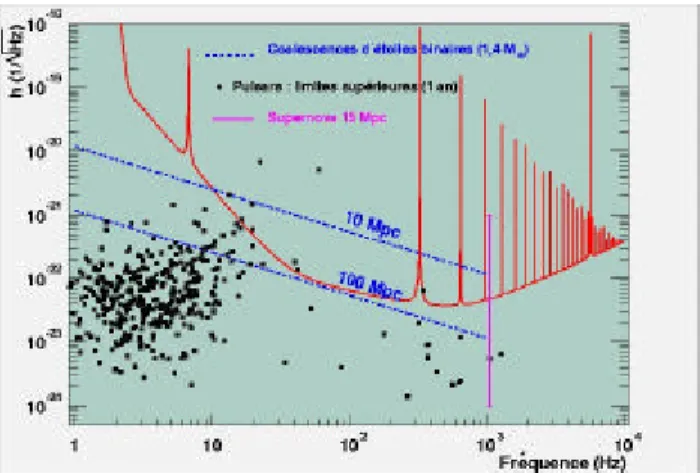
The Virgo planned sensitivity is shown in Figure 5 as a function of the GW frequency. Below 4 Hz the interferometer sensitivity is limited by the residual seismic noise. Above this frequency and below 500 Hz the limitation is given by thermal noise in the suspension wires and inside the mirror. Several peaks due to the wire violin modes are visible in the spectrum. Finally above 500 Hz the limitation is given by the photon shot noise.
Figure 5: The Virgo expected spectral sensitivity; for comparison the amplitude of several expected sources are
plotted.
For comparison several expected sources are shown on the same graph. Virgo will be able to test the GW emission upper limits of several spinning galactic neutron stars and will look for coalescing binaries up to distances of 40 Mpc. The amplitude signals from supernova being very uncertain, Virgo could be either limited to galactic supernovae either be sensible up to the distance of the Virgo cluster.
In any case Virgo and the similar detectors entering now into operation will provide an enhancement of about 2-3 order of magnitude in sensitivity with respect to the existing detectors. Improvement will be even larger at low frequency were Virgo will take advantage of the excellent seismic isolation.
4 VIRGO STATUS AND PLANS
The construction of the Virgo detector is determined by the planning of the infrastructures construction. The construction of the central area started in 1996 and was completed in 1998. The part of the interferometer contained in the central area is shown in Figure 3. Starting in 1999 the installation of all the equipment in the central area proceeded in parallel with the construction of the two arms. During this first phase of assembly the Fabry-Perot input mirrors were replaced by totally reflecting mirrors in order to start running a simple Michelson interferometer with recycling: this is known as the central interferometer [19].
The commissioning of the central interferometer is the first step in the commissioning of Virgo. Apart from the
absence of the long Fabry-Perot cavities the central interferometer uses all the technology developed for Virgo. The only other relevant difference are for the mirrors, which are small 2 inches diameter mirrors attached to larger aluminium holders having the same size as the final mirrors.
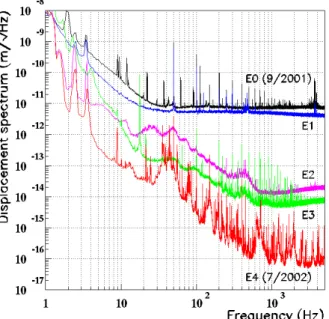
Central interferometer commissioning [20] started in the spring of 2001. The first phase of the commissioning was performed by means of a low power (100 mW) auxiliary laser, since the final laser was not available yet. During this phase the various control systems were progressively started. At the very beginning the interferometer was run in the simple Michelson configuration (the recycling mirror was kept misaligned) and two engineering runs (E0 and E1) were performed in this configuration. Then the recycling cavity was put into operation achieving a recycling factor of about 100. During this phase the mirrors relative position was controlled with a precision of 10-12 m. In this configuration the automatic alignment was also partly running. By means of a quadrant photodiode detecting the dark fringe beam, the relative alignment of the two interfering beams was controlled with a precision of 10-7 rad. Again two engineering runs were performed in this configuration (E2 and E3) and duty cycles of the order of 98% were attained (continuous locking period as long as 50 hours were obtained). During the last period of the commissioning the 10 W laser was used. Due to some losses in the injection optics the actual power entering the interferometer was about 2 W but, thanks to the recycling technique, it was possible to get 200 W impinging on the beam splitter.
Figure 6: Spectra of interferometer displacement noise measured during the five engineering runs performed with
the Virgo central interferometer.
The displacement sensitivity measured with the central interferometer during the various engineering runs is shown in figure 6. In less than one year the sensitivity
was improved by 5 orders of magnitude at 1 kHz and by 3 orders of magnitude at 10 Hz. Best sensitivity was slightly better than 10-16 m/Hz at 1 kHz and about 10-13 m/Hz at 10 Hz. The limitation to the sensitivity measured with the full system during E4 mostly comes from the residual laser frequency noise. During this test the laser was frequency stabilized to the input mode-cleaner. The residual mode-cleaner length vibration, driven by control noise exciting mechanical resonances in the benches supporting the cavity mirrors, was strongly limiting the laser frequency stability and as a consequence the interferometer performances in the few Hz to 250 Hz frequency range. This is one of the systems that is going to be improved during the upgrade to the final Virgo. At lower frequencies the limitation was coming from alignment control noise while at higher frequency some of the visible peaks have been identified as mirror supports internal resonances (these peaks will disappear when they will be replaced by the final Virgo mirrors).
The central interferometer was shut down last July in order to proceed with the assembly of the 3 km interferometer. Meanwhile the construction of the infrastructure was completed. The installation of the 3 km long tube proceeded in parallel with the construction of the arms and is going to be completed by the end of the year. The installation of the final mirrors just started and is going to be also completed early next spring. The commissioning of Virgo will start in 2003 and the first technical runs are expected to occur by the end of year. The first scientific run should follow in 2004.
5 CONCLUSIONS
The construction of the Virgo detector is approaching its completion. The preliminary tests performed with the central interferometer were successful and trigger several improvements that will be implemented in Virgo. The experience gained with the central interferometer will speed up the commissioning of Virgo.
Virgo will be part of a network of laser interferometers dedicated to gravitational wave detection with a sensitivity 2 to 3 orders of magnitude better than present detectors at a few hundreds Hz. Moreover thanks to its advanced seismic isolation Virgo will allow to start exploring the frequency range between 10 Hz and 100 Hz.
6 REFERENCES
[1] C.W.Misner, K.S.Thorne, J.Wheeler, ‘Gravitation’ Ed. W.H.Freeman, San Francisco (1973)
[2] K.S.Thorne, Gravitational radiation in: 300 Years of Gravitation, Ed. Cambridge University Press (1987) [3] Hulse and J.H.Taylor; The astrophysical Journal 195 L51 (1975). J.H.Taylor et al. Nature 355 (1992) 132 [4] R.Weiss, Quarterly Progress Report of the Research Laboratory of Electronics, MIT 105 (1972) 379
[5] R.W.P.Drever, ‘Interferometric detectors for gravitational radiation’ in: Gravitational Radiation, Proc.
Les Houches Summer Institute, ed. T.Piran and N.Deruelle (1982)
[6] A.Giazotto, Phys. Rep. 182 6 (1989) 365-425 [7] P.R.Saulson, Phys. Rev. D 42 (1990) 2437 [8] Virgo collaboration, Final Design (1995),
F.Marion et al. in Proceedings of the 3rd Edoardo Amaldi Conference (S.Meshkov Ed.) AIP Conference Proceedings 523, p.110, Melville, New York (2000) [9] F.Bondu et al., Classical and Quantum Gravity. 19 (2002) 1829-1833
[10] R.Flaminio et al ; Class. and Quantum. Grav. 19 7 (2002) 1857-1863
[11] G.Ballardin et al., Rev. Sci. Instrum. 72 3643 (2001) [12] G.Losurdo et al., Rev. Sci . Instrum. 70 2507 (1999) [13] S.Braccini et al., Rev. Sci. Instrum. 67 2899 (1996) [14] A.Bernardini et al, Rev. Sci. Instrum. 70 3463 (1999) [15] G.Losurdo et al., Rev. Sci. Instrum 72 3653 (2001) [16] H.Heitmann and C.Drezen, Rev. Sci. Instrum. 98 (1997) 3197, F.Bellachia et al. Nuclear Instruments and Methods in Phys. Res. A 413 (1998) 151
[17] R.Flaminio and H.Heitmann, Phys Lett A 214 (1996) 112-122
[18] F.Cavalier, ‘Le controle globale de Virgo’ These d’Habilitation a diriger des Recherches, Universite Paris Sud, LAL 01-69 (2001)
[19] F.Acernese et al., Class. Quantum Grav. 19 7 (2002) 1857-1863
[20] M.Barsuglia et al., VIR-NOT-LAP-1390-224 [21] D.Babusci et al., Phys. Lett. A 226 (1997) 31-40