HAL Id: hal-01265771
https://hal.archives-ouvertes.fr/hal-01265771
Submitted on 1 Feb 2016HAL is a multi-disciplinary open access archive for the deposit and dissemination of sci-entific research documents, whether they are pub-lished or not. The documents may come from teaching and research institutions in France or abroad, or from public or private research centers.
L’archive ouverte pluridisciplinaire HAL, est destinée au dépôt et à la diffusion de documents scientifiques de niveau recherche, publiés ou non, émanant des établissements d’enseignement et de recherche français ou étrangers, des laboratoires publics ou privés.
Plasmas for High Speed Flow Control
R. Joussot, S. Coumar, V. Lago
To cite this version:
R. Joussot, S. Coumar, V. Lago. Plasmas for High Speed Flow Control. Aerospace Lab, Alain Appriou, 2015, �10.12762/2015.AL10-04�. �hal-01265771�
Plasmas for Aeronautics
Plasmas for High
Speed Flow Control
R. Joussot, S. Coumar, V. Lago(ICARE, CNRS, Orléans)
E-mail: [email protected]
DOI : 10.12762/2015.AL10-04
T
his paper presents experimental activities focused on supersonic flow control with
plasma and MHD actuators. This work is carried out at ICARE, a laboratory located
at the CNRS Campus in Orléans. The study of aerothermodynamic physics, one of the
research fields of ICARE, is conducted with the experimental platform FAST consisting
of three supersonic/hypersonic wind tunnels involved in aerothermodynamic testing for
hypersonic flight and space technology.
Introduction
Flow control research in the compressible regime plays a major role in many applications, such as aerospace, defense and transportation. Over the past two decades, considerable research effort has been made on the use of plasma-based devices in high speed flow control applications, both numerically and experimentally [1-5]. Depending on the nature of the flow, ionized or neutral gas, two types of plasma-based devices can be used. In the case of neutral gas flows, plasma actuators are used and their action is based on the interaction of the electric field with the flow (EHD interaction). If the flow is already ionized, then magnetic systems are preferred and are based on the interaction of a magnetic field with the charged particles of the ionized flow (MHD interaction).
Although the ability of plasma-based devices to control high speed flows no longer needs to be demonstrated, the complexity of the wide field of competences involved in these research areas (compressible fluid mechanics, plasma discharge physics and magneto-hydrodyna-mics) implies that many studies must still be conducted to gain a better understanding of how and why a high speed flow is modified when plasma-based devices are used. In this respect, experimental investi-gations are carried out at ICARE, a CNRS laboratory located in Orléans, with the experimental platform FAST (Facilities for Aerothermodyna-mics and Supersonic Technologies). In particular, the studies carried out by our group focus on supersonic and hypersonic flow modifica-tions by plasma-based devices, under rarefied condimodifica-tions. Our domain of applications concerns the flight of vehicles at high altitude (i.e., low pressure) and atmospheric re-entry aerothermodynamics.
During the re-entry phase into a dense gas atmosphere, spacecraft flying at hypersonic velocities are exposed to severe conditions and the mission planning must delicately balance three requirements: decelera-tion, heating and accuracy of the landing. Thus, one of the promising technologies consists in using active flow control methods with plas-ma-based devices. This could potentially reduce the heat flux locally by increasing the shock stand-off distance, reduce the vehicle speed by increasing the wave drag and therefore the ballistic coefficient, enhance
the vehicle stability and trimming by controlling the flow leading to the simplification or elimination of the flaps, and avoid black-out transmis-sion by using MHD to optimize communication links.
In order to improve or increase the effects of these plasma-based devices, the coupling of EHD-MHD devices could be used. Thus, electrically or magnetically generated forces act on the ionized com-ponent of the flow impacting the vehicle and can modify the shock wave shape, the shock stand-off distance, or the surface heat flux, for instance. Even though these forces act only on a small ionized part of the whole flow field, proper orientation of the field lines (electric or magnetic) applied over a partial body surface region ensures that a global body force can be exerted on the entire flow. When electrical discharges are used, substantial changes in the structure and proper-ties of the high speed flow field have been demonstrated to occur in the vicinity of the vehicle where the actuator is located. Compared to mechanical ones, active actuators like plasma-based devices have a fast response time.
From a general point of view, a plasma actuator is a simple electrical device based on the use of a gas discharge. Among the most used types of plasma actuators, one can find those based on surface die-lectric barrier discharge (dbd) with linear or serrated electrode design [6-9], direct current (dc) discharge [10-11], filamentary discharge [12], arc discharge [13] and corona discharge [14]. The main limi-tation in preferring the use of a particular type of plasma actuator is often driven by the flow conditions, especially the pressure condition. In rarefied flow regimes, corona and glow discharges are mainly used, with other types of plasma actuators being scarcely ever used owing to their working limitation imposed by the discharge physics itself. In the case of glow discharges working at a low pressure, the ionic wind cannot be considered to explain the observed modifications of the flow. Contrary to plasma actuators working at atmospheric pressure, the values of both the electric field and the net charge density are too low to obtain a significant EHD force and, therefore, to produce an ionic wind. Thus, under supersonic flow conditions, thermal effects, including surface and bulk (i.e., gas) heating, are commonly consi-dered as the main physical mechanisms responsible for aerodynamic
effects [15-17]. Nevertheless, experiments still remain that can hardly be explained by thermal effects alone [17-20]. Especially, those in which a change in the discharge polarity leads to various aerodyna-mic effects [17, 20]. In this study, plasma flow control experiments are carried out with the MARHy wind tunnel (supersonic/hypersonic rarefied flows). The experiments began in 2004 with the Ph.D. thesis of E. Menier [21] and, as from this date, they gave rise to a better understanding of the respective contributions of the thermal effects and the purely plasma ones on the flow field modification [22, 23]. MHD prospective applications in aerodynamics were described fifty years ago by Sears [24]. Shortly after, Ziemer [25] numerically and experimentally investigated the influence of an external magnetically induced field on the shock stand-off distance, showing a notable increase with respect to the situation without magnetic induction. The bow shock wave formed in front of vehicles flying at hypersonic speeds produces a compression and a strong heating of the gas. Close to the surface, the temperature is high enough to ionize the gas, leading to a significant level of MHD interaction processes if a magnetic field is applied. MHD interaction can generate forces that enable the fluid dynamic configuration to be modified. For instance, it is possible to move the shock front away and then decrease the thermal flux toward the wall protection. Several studies have been done on this topic, such as the experimental investigations carried out by Cristofolini et al. [26] and Gülhan et al. [27], and the numerical investigations presented by Yoshino et al. [28]. For this purpose we have carried out a set of experiments with the plasma wind tunnel PHEDRA [29].
Modification of shock waves by glow discharge
The MARHy wind tunnel
The MARHy low density wind tunnel is dedicated both to academic and industrial research. A schematic view of the wind tunnel is pres-ented in Figure 1. It consists of three parts: the settling chamber with a diameter of 1.3 m and a length of 2.0 m, the test chamber with a diameter of 2.3 m and a length of 5.0 m, and a third chamber in which a diffuser is installed. The diffuser is connected to the pumping group by a vacuum gate. A powerful pumping group with 2 primary pumps, 2 intermediary Roots blowers and 12 Roots blowers ensures the low density flow conditions in continuous operating mode. When supplied through different nozzles, the wind tunnel generates subsonic, superso-nic and hypersosuperso-nic flows between Mach 0.6 and Mach 22, and covers a large range of Reynolds numbers from 102 up to 105. Figure 2 shows
the working conditions of the MARHy wind tunnel, where the Reynolds number is based on a model length of 10 cm. This study was carried out with a contoured Mach 2 nozzle, giving a uniform flow distribution throughout the test section with a core 12 cm in diameter. The nominal operating conditions are summarized in Table 1.
Figure 1 - Schematic view of the MARHy wind tunnel
Figure 2 - Mach-Reynolds diagram for the MARHy wind tunnel
Stagnation conditions Free stream conditions p0=63Pa T0=293K 0=7.44 10 -4 kg.m-3 pI=8Pa I=1.7110 -4kg.m-3 TI=163K I=1.1010 -5 Pa.s UI=511 m.s-1 I=0.375 mm MI=2 qm=3.3410 -3kg.s-1
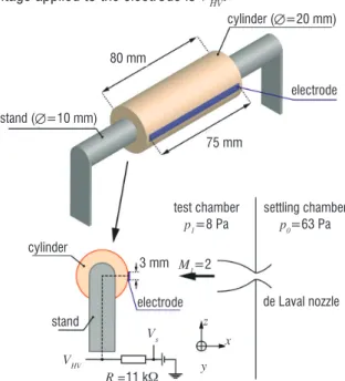
Table 1 - Operating conditions The cylinder configuration
Circular cylinder and discharge setup
The model is a circular cylinder made of alumina, with a diameter of 20 mm and a spanwise length of 80 mm (Figure 3). An aluminum electrode is flush mounted on the cylinder in the spanwise direc-tion. It is 0.5 mm-thick, 75 mm-long and 3 mm-wide. The cylinder is mounted in the test section with its longitudinal axis perpendicular to the main flow direction. The corresponding Reynolds number is 159. The plasma is produced with a glow discharge generated by connecting the electrode to a high voltage dc power supply (Spellman SR15PN6) through a resistor (Rs = 11 kΩ). The electrode is negati-vely biased compared to the rest of the device (i.e., the wind tunnel metallic parts), which is grounded and collects electric charges from the plasma, ensuring the current looping. The voltage Vs is fixed by means of the power supply, which delivers the discharge current IHV. The voltage applied to the electrode is VHV.
Figure 3 - Schematic representation of the cylinder
settling chamber windows
diffuser test chamber pumping group stand (=10 mm) stand cylinder (=20 mm) cylinder electrode
electrode de Laval nozzle
3 mm M1=2 VHV Rs=11 k Vs z x y 80 mm test chamber p1=8 Pa settling chamber p0=63 Pa 75 mm ReL (L =10 cm) 0 5 10 15 20 25 Mach number M 106 105 104 103 102 gas inlet
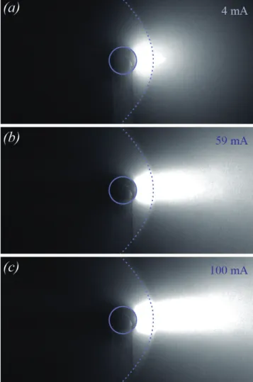
Figure 4 - Images (recorded with the iccd camera) of the flow field modified by the plasma discharge: (a) -0.46 kV and 4 mA, (b) -1.37 kV and 59 mA, and (c) -1.94 kV and 100 mA. The dotted line represents the shock wave shape of the baseline.
Modification of the flow field by the plasma discharge
Figure 4 shows the iccd images of the shock wave modified by the discharge. The natural shock wave shape is superimposed on each image, in order to facilitate comparison between the different cases. As can be observed, the plasma changes the shape of the shock wave locally, pushing it upstream of the flow. The symmetrical shape is maintained, but the "curvature" of the shock wave is slightly modi-fied far from the stagnation line. The stand-off distance on the sta-gnation line is estimated, for each electrical discharge configuration, from the experimental images. Lago et al. [22] showed that the stand-off distance undergoes a linear increase with the applied voltage. In this study, the stand-off increases when the plasma is created in the region upstream and downstream from the shock wave. Thus, we can assume that the local flow properties in the vicinity of the shock wave have been modified. This approach can be compared with the one proposed by Hayes and Probstein [30], who showed that the shock stand-off distance in front of a cylinder is a function of the density ratio across the shock wave on the stagnation streamline. Three types of effects can be considered to explain why the shock wave is pushed upstream: surface heating of the electrode, volumetric heating of the gas upstream from the electrode where the plasma is present and the influence of the ionization degree. Each of these effects was studied separately, in order to quantify its respective influence on the shock wave modification.
Analysis of the plasma effects
In order to evaluate the influence of the surface and volumetric heating induced by the plasma, we have simulated these effects numerically and separately [22]. The results have shown that no thermal effects are responsible for the shock wave shape modification. These results are consistent with optical temperature measurements, which show that the gas temperature remains below 400 K (Figure 5).
Figure 5 - Comparison between N2 and N2+ rotational temperatures (i.e., gas temperature) with flow (M1 = 2) and without flow versus the discharge current.
Since thermal effects are not responsible for the flow modifications observed, other properties of the plasma must be considered to explain the measurements. For this purpose, we modify the empirical relation of the shock stand-off distance proposed by Ambrosio and Wortman [31], in order to express the stand-off distance as a function of the ioni-zation degree of the plasma. If we assume that a normal shock wave is present on the stagnation streamline, then the isentropic relation gives
(
)
(
)
2 1 2 2 1 1 1 2 1 M M γ ρ ρ = γ + + − (1)where M1 is the Mach number upstream from the shock wave, is the isentropic exponent and is the volumetric density. The subs-cript 1 is related to the upstream flow condition and the subscript 2 is related to the downstream condition. When the electrical discharge is switched on, the law of mass conservation can be expressed by the following relation: * 2 2 1 1 ρ ρ ρ = ρ (2)
where the superscript * is related to the ionized state of the flow (i.e.,
a plasma is present). The isentropic exponent * of a diatomic plasma
in non-local thermodynamic equilibrium is determined with the fol-lowing relation, proposed by Burm et al. [32]
(
)
(
)
(
)
* * * 2 1 2 1 i 1 i p i v c c θ θ γ θθ α
α
α = + + − + − − (3)where i is the ionization degree defined as the ratio of the electron
density ne to the neutral density n1, and = Tgas/Te is the thermal
disequilibrium between the gas temperature Tgas and the electron tem-perature Te.
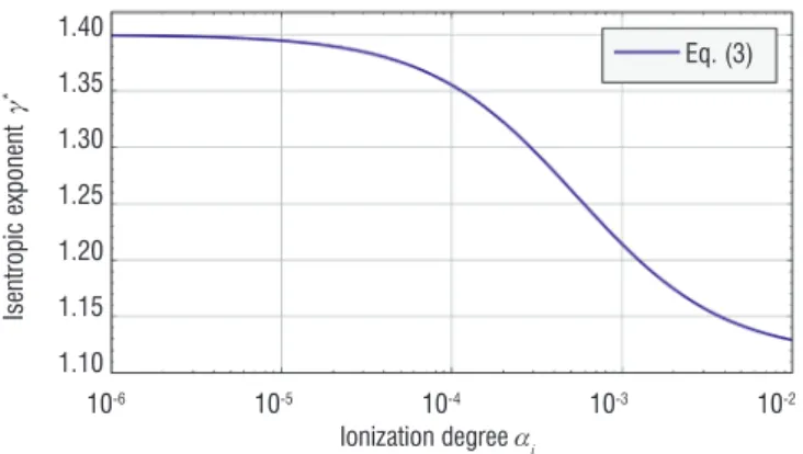
Figure 6 shows the theoretical variation of * according to an
ionization degree ranging from 10-6 to 10-2, corresponding to
a weakly ionized plasma. The gas temperature was fixed at
Tgas = 375 K (from the results shown in Figure 5) and the elec-tronic temperature was fixed at Te = 1 eV. The isentropic expo-nent decreases from 1.4 (non-ionized gas) to about 1.12, and
Rotational temp. Trot (K) N2 + - without flow N2+ - with flow N2 - with flow 0 10 20 30 40 50 60 Discharge current IHV (mA)
600 550 500 450 400 350 300 250
remains almost constant for higher ionization degrees. It can be seen that the isentropic degree begins to decrease significantly for i > 10-5, which corroborates the hypothesis of Bletzinger et
al. [2], who argued that for a very low ionization degree (≈ 10-7)
the flow modification in an ionized gas is predominantly due to thermal effects.
Figure 6 - Isentropic exponent of a plasma as a function of its ionization degree (Tgas = 375 K and Te = 1 eV).
The upstream Mach number of the plasma state M1* can be
calcula-ted with Equations (1) and (2) as a function of the isentropic exponent of the plasma defined with Equation (3). For the values of * plotted in
Figure 6, Figure 7 shows that the plasma is responsible for a decrease in the Mach number upstream from the shock wave.
Figure 7 - Mach number of an ionized flow upstream from a normal shock wave as a function of the isentropic exponent of an ionized gas.
The stand-off distance * in an ionized gas can be calculated by
modifying the empirical relation of Ambrosio and Wortmann [31] as follows: * *2 1 4.67 0.386exp cyl R = M ∆ (4)
where Rcyl is the cylinder radius and M1* is the Mach number of the
io-nized flow upstream from the shock wave (Figure 7). Figure 8 shows the variation in the stand-off distance for a plasma flow according to its ionization degree. The open symbols are the experimental values of calculated from the iccd images for the applied voltages tested. The values of measured experimentally correspond approxima-tely to an ionization degree ranging between 4×10⁻⁵ and 3×10⁻⁴.
These values of i allow the electronic density to be calculated by
considering a neutral particle density behind the shock wave of n2 = 5×10²¹ m-3. For these values of
i and n2, the electron density
varies between 2×10¹⁷ m-3 and 1.5×10¹⁸ m-3, which is of the same
order of magnitude as those mentioned in the literature for this type of discharge. In addition, our measurements show that the increase in is linear with IHV [22], which is the same type of relation as that
existing between the electronic density and the current density (i.e., the discharge current IHV). The increase in with the electrical parameters of the discharge is then explained by a modification of the flow condi-tions via a decrease in the isentropic exponent of the flow. The nature of the flow in the vicinity of the shock wave is therefore of great impor-tance in explaining why increased when the discharge was active.
Figure 8 - Stand-off distance for a flow of ionized gas as a function of the ionization degree of the plasma. The open symbols correspond to the experi-mental values of measured with the plasma actuator.
The flat plate configuration
Description of the flat plate and actuators
The model under investigation is a flat plate (100 long, 80 mm-wide and 4 mm-thick) made of quartz, with a sharp leading edge of 15°. The flat plate is mounted in the test section, 183 mm downstream from the nozzle exit (Figure 9). The Reynolds number, based on the flat plate length L and calculated with the experimental inflow conditions (Table 1), is 794. The Knudsen number based on the same experimen-tal conditions is 0.019, which corresponds to the slip-flow regime.
Figure 9 - Schematic view of the flat plate in the case of the plasma actuator
The plasma actuator is composed of two aluminum electrodes (80 mm-long, 35 mm-wide and 80 µm-thick), which are flush mounted on the upper surface of the flat plate (Figure 10a). The first elec-trode, called the active elecelec-trode, is set at the leading edge of the plate and is connected to a high voltage dc power supply (Spellman, SR15PN6) through a resistor, while the second one is grounded. The glow discharge is generated by applying a negative dc potential to the active electrode, acting as a cathode. Previous works have shown that, for this geometry, one of the effects of the plasma actuator on the flow field is caused by the heating of the surface [11]. In order
Isentropic exponent * Stand-off distance *(mm) Eq. (3) 10-6 10-5 10-4 10-3 10-2 Ionization degree i 1.40 1.35 1.30 1.25 1.20 1.15 1.10 19 18 17 16 15 14 13 12 2.1 2.0 1.9 1.8 1.7 1.6 Mach number M1 * Eq. (1) - (3) 1.40 1.35 1.30 1.25 1.20 1.15 1.10 Isentropic exponent * Eq. (4) experimental stand
de Laval nozzle HV electrode
grounded flat plate M1=2 VHV Rs=11 k Vs z x y test chamber p1=8 Pa settling chamber p0=63 Pa 10-6 10-5 10-4 10-3 10-2 Ionization degree i electrode
to reproduce the surface heating produced by the plasma actuator, a heating element was used. The heating actuator, namely the hea-ter, is composed of a 0.15 mm-diameter resistance wire (28 m-1,
Cu-Ni-Mn alloy) embedded between two layers of polyimide film. The heater is flush mounted on the flat plate surface instead of the active electrode (Figure 10b). The longitudinal distribution of the resistance wire was not constant, in order to reproduce the temperature distribu-tion measured with the plasma actuator. The heater was connected to a dc power supply (0-60 V, 0-2.5 A).
Figure 10 - Schematic views of the flat plate with: (a) the plasma actuator, and (b) the heater.
Figure 11 - Longitudinal distribution of the wall temperature along the flat plate in the case of the plasma actuator.
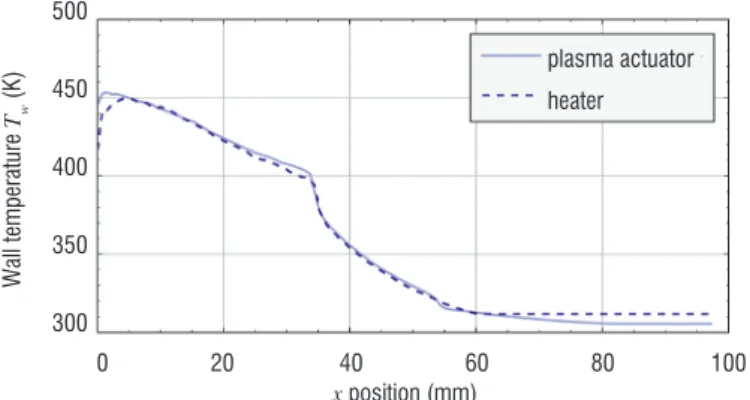
Figure 12 - Comparison of wall temperature distributions along the flat plate between the plasma actuator and the heater.
The surface heating is due to the electrode bombardment by ions and neutrals from the plasma to the wall. This type of heating mechanism is due to the electric field in the vicinity of the cathode. Given that the flat plate has a beveled leading edge, the electric field in the vicinity of the cathode varies along the X-direction. The longitudinal
distribu-tion of the surface temperature is not constant, as evidenced by the infra-red camera measurements presented in Figure 11. The tempe-rature distribution is not homogeneous along the plate and presents the highest values close to the leading edge. The home-made heater allows this longitudinal temperature distribution to be reproduced by choosing an adequate value for the current heater IHE (Figure 12). A maximum wall temperature value of Tw,max ~ 510 K can be repro-duced with the heater.
Description of the natural flow
The flow field around the flat plate was first investigated without any actuation, corresponding to the study of the natural flow (namely, the baseline). In this case, the shock wave was experimentally visua-lized with the glow-discharge flow visualization technique. Figure 13 shows an image of the baseline around the flat plate, visualized with the iccd camera. This image results from the averaging and post-processing of 300 snapshots of the flow field recorded with the iccd camera. The air flows from left to right.
Figure 13 - Image of the natural flow field around the flat plate obtained with the glow-discharge flow visualization technique.
The shock wave is readily recognized on the image obtained with the iccd camera, enabling the estimation of its shape. Under our condi-tions, the shock wave shape for the baseline is hyperbolic and can be described by the following equation:
1/2 2 1 2 3 1 z x c c c = + + (5)
where x and z are the shock wave coordinates in the Cartesian coor-dinate system (centered on the leading edge) and c1, c2 and c3 are the geometric coefficients of the hyperbola. The shock wave angle corresponds to the angle of the hyperbola asymptote. The coefficients
c1, c2 and c3 are estimated by fitting (least squares method) the shock wave position in the iccd images, enabling the shock wave angle to be calculated. For the baseline, the value of is 36.77°. The shock wave is slightly detached from the leading edge of the plate because of the rarefaction effects. The order of magnitude of the shock wave stand-off distance is 1–2 mm. For the baseline, the wall temperature is homogeneous (286.5 K < Tw < 288.4 K).
Modifications induced by the plasma actuator
When the high voltage is switched on, gas above the cathode is io-nized and weakly ioio-nized plasma is created. Visually, it corresponds to the luminous area shown in Figure 14. The dark area above the cathode corresponds to the plasma sheath. The plasma discharge
35 mm a)
z y
x
HV electrode grounded electrode
electrode not wired heater b) 35 mm 35 mm 20 mm 4 mm 15° Wall temperature Tw (K) Wall temperature Tw (K) OFF - 0.81 kV -1.05 kV -1.19 kV plasma actuator heater 0 20 40 60 80 100 x position (mm) 0 20 40 60 80 100 x position (mm) 600 550 500 450 400 350 300 500 450 400 350 300
induces a modification of the shock wave that is deflected outward from the flat plate surface, as illustrated in Figure 14. For the electri-cal configurations experimentally tested, the hyperbolic shape of the shock wave is preserved, allowing Eq. (5) to be used to estimate the shock wave angle. In addition, the order of magnitude of the shock wave stand-off distance remains within the 1–2 mm-range. Figure 15 shows the increase in the shock wave angle with the applied voltage. This variation can be approximated by the following equation
(
)
{
}
0 1 exp n ign HV a b V V β β= + − − − (6)where a = 5.89° and b = 2.65 kV-n, n = 1.28 are the best-fit
para-meters and 0 = 36.77° is the shock wave angle of the experimental
baseline.
Figure 14 - Image of the flow field modified by the plasma actuator (VHV = -1.57 kV and IHV = 74 mA)
Figure 15 - Shock wave angle versus the applied voltage Analysis of the plasma effects
In the rarefied flow regime, one of the main effects expected to be responsible for modifying the shock wave is the heating of the model surface [33], which induces a displacement effect [30]. The flow viscosity above the heater is modified, leading to an increase in the boundary layer thickness and, consequently, a shifting of the shock wave outward from the flat plate surface (i.e., increases). In this experiment, a Pitot survey of the flow above the cathode shows the increase in the boundary layer thickness (Figure 16). At the longitu-dinal position x = 17.5 mm (i.e., in the middle of the cathode), the boundary layer thickness is estimated by measuring the wall-normal position of the maximum pressure. When a plasma discharge is pres-ent (with VHV = -1.47 kV and IHV = 39 mA), the boundary layer thic-kness increases by 60%, showing the displacement effect induced by the plasma actuator.
Another possible effect produced by the plasma discharge is the bulk heating of the gas above the flat plate surface. In order to investigate this, temperature measurements above the cathode were performed by Me-nier et al. [11] with optical emission spectroscopy. These measurements were based on rotational temperature measurements from the N2 second positive system and the N2+ first negative system at = 337.14 nm and
= 390.4 nm, respectively. The results showed that the gas tempera-ture deduced from the rotational temperatempera-ture is weakly increased by the discharge, meaning that the bulk heating is low.
Figure 16 - Pitot pressure profiles in the wall-normal direction at x = 17.5 mm in the case of the plasma actuator
In order to differentiate the surface thermal effect from other effects purely due to the plasma discharge, experiments were carried out using the heater as actuator. Numerical simulations were perfor-med by using the 2D compressible Navier–Stokes equations with the boundary conditions adapted to match the physical phenomena involved in the slip-flow regime, in order to simulate the surface ther-mal effects of the actuators [23, 34]. Figure 17 plots the shock wave angle versus the maximum surface temperature (measured close to the leading edge, Figure 11) for the two actuators (plasma and heater) and for the numerical simulation.
Figure 17 - Comparison of the shock wave angles measured with the two types of actuators (plasma actuator: diamond; heater: square) and calculated with the numerical simulation [23] (circle)
For any given value of Tw,max, the shock wave angle measured with the heater is lower than the value estimated with the plasma actuator. This result is confirmed by the numerical simulation, which exhibits an increase in similar to that measured with the heater [23]. When the heating element is used, it is reasonable to assume that only a purely thermal effect at the model surface induces the flow modifi-cations observed. In this case, the mechanism involved in the shock wave angle increase is the displacement effect. The experimental data presented in Figure 17 provide a direct estimation of the surface
Shock wave angle
(°) Eq. (6) experimental 44 43 42 41 40 39 38 37 36 z position (mm) Off plasma - VHV = -1.02 kV 10 20 30 40 50 60 Pitot pressure (Pa)
50 40 30 20 10 0
Shock wave angle
(°)
plasma actuator
300 350 400 450 500 550 600 650 700 Maximum wall temperature Tw,max (K)
44 42 40 38 36 0.0 -0.5 -1.0 -1.5 -2.0 Applied voltage VHV (kV)
heating effectiveness when the plasma actuator is used. The purely thermal effect at the flat plate surface therefore accounts for almost half of the total shock wave modification when the plasma actuator is used [23]. Moreover, the contribution of surface heating to the shock wave modification decreases with the discharge current, meaning that the efficiency of other actuation modes in the shock wave modi-fication increases.
It is clear that the plasma actuator modifies the flow field in a way other than via a thermal effect alone at the electrode surface. In addition, previous studies [11, 12] have shown that the volu-metric heating is rather low (+10 K for a plasma discharge with a power ranging between 30 W and 90 W), meaning that other effects induced by the discharge must be studied to explain the shock wave modification observed. Investigation with a cylinder has shown that the flow field is modified by a plasma actuator applied over the cylinder surface, because the ionization rate is strong enough to decrease the value of the isentropic coefficient of the gas, leading to an increase in the stand-off distance. This makes us believe that the ionization rate could play a key role in the explanation of the observed modifications over the flat plate, since the flow conditions are the same and the plasma actuator devices are similar.
Supersonic flow modification by a plasma actuator and MHD
The PHEDRA wind tunnel
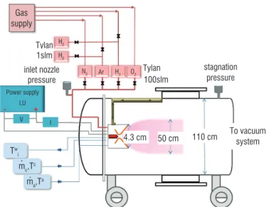
This experimental investigation has been carried out in the superso-nic low-pressure plasma wind tunnel PHEDRA (Figure 18). This wind tunnel is a plasma ground test platform used to simulate low-pressure flight conditions in the upper layer of planetary atmospheres.
Figure 18 - General scheme of the PHEDRA wind tunnel
PHEDRA is a wind tunnel (with a length of 4.3 m and 1.1 m in diameter) where the low pressure level is maintained with a three-stage pumping group ensuring a residual pressure in the vacuum chamber of around 2 Pa during experiments. The rarefied super-sonic plasma flows are produced with a dc arc jet generator. The arc is obtained between the cathode tip and the nozzle throat of the anode. The cathode is a water cooled copper support of 5 mm in diameter, rounded at the tip with a 1.6 mm-diameter
zir-conium insert, on which the cathode spot is found. The anode is convergent up to the position of the cathode tip, then straight for 6 mm with a diameter of 4 mm and then divergent. It is made of cop-per, with a tungsten insert in the straight 4 mm diameter segment. A vortex movement of the gas inside the arc chamber is applied to obtain stable arc conditions. The current ranges from 50 to 250 A, while the mass flow rate can be varied from 0.1 to 0.3 g.s-1, thus
yielding a high specific enthalpy of 5-30 MJ.kg-1. All gases are
supplied directly along the anode. The advantages of this type of plasma generator are the stable plasma jets with a long standing time (over a day in air) at large dimensions (500 mm-diameter and 1500 mm-length at 0.1 Torr) and low jet contamination due to the very small cathode erosion of less than 1 ng.s-1 compared to
the gas mass flow of at least 0.1 g.s-1. The PHEDRA wind tunnel
is equipped with proper instrumentation for the acquisition of the plasma operating parameters and real-time evaluation of the spe-cific enthalpy. The operating parameters and the acquisition chain are shown in Figure 18. The experiments presented in this paper were carried out with two different gas mixtures, a mono-atomic gas with argon and a molecular one with air (80% N2 / 20% O2). The operating plasma conditions for each of these are listed in Table 2.
Argon 80% N2 / 20% O2
Mass flow rate (g.s-1) Arc current (A) Arc voltage (V) Specific enthalpy (MJ.kg-1) 0.47 100 32 3.2 0.32 100 55 10.6
Table 2 - Operating plasma conditions Test models
Two test models were used in these experiments. A blunt body was aligned with the nozzle centerline for the study of the bow-shock (Configuration 1) and a flat plate was used for the study of the boun-dary layer (Configuration 2). The details of these configurations are illustrated in Figure 19.
Figure 19 - Experimental configurations: blunt body (left panel) and flat plate (right panel)
The models are made of non-magnetic materials and they are inserted into the plasma flow by means of a movable support operating with an air-compressed system. For each configuration, two identical models were manufactured and mounted on the movable system, one of them carrying the permanent magnet that allows the effect of the magnetic field to be tested during the same experiment. The magnetic field is created with neodymium magnets fixed on the models. Each magnet has a square section with 10 mm sides and a 3 mm thickness, and its magnetic field strength at the surface is Bs = 0.278 T, perpendicular to the model surface. The magnet pieces have been superimposed to strengthen the magnetic field. Unfortunately, the heat flux leads to the loss of magnetization of the magnets, forcing us to change the magnets for each new experiment.
Tw i mc,Tc ma,Ta Gas supply H2 H2 Tylan Tylan 110 cm Magnets Magnets 14 mm 74 mm 80 mm 30 mm 20 mm 50 mm 10 mm Plasma Plasma 50 cm 4.3 cm 1slm 100slm inlet nozzle pressure stagnation pressure To vacuum system N2 Ar H2 O2 V ∙ ∙ I Power supply I,U
Results
The free stream has been characterized in previous works, in particu-lar the velocity, temperatures and electronic parameters (ne and Te) of the plasma flow [29, 35, 36].
Table 3 summarizes the parameter values characterizing the plasma flow at the nozzle exit. The temperatures of the heavy species in the flow have been determined by optical spectros-copic analysis. In air plasma flows, the rotational and vibrational temperatures are obtained by fitting the N2+ experimental spectra
with the simulated one. In argon plasma flows, the temperature was determined using the Boltzmann plot method by analyzing the atomic emission spectra.
Argon 80% N2 / 20% O2
Velocity (m.s-1) 5500 6200
Temperature (K) 2300(Texc) 3500(Trot
) 9000(Tvib)
Electron density (m-3) 1.21018 3.51018
Electron temperature (K) 3900 10.000
Table 3 - Plasma flow parameters at the nozzle exit.
Configuration 1: blunt body
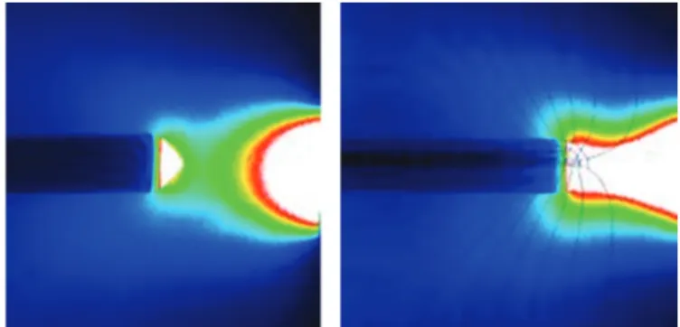
Two identical blunt bodies are used for this experiment. The model is hollow and made of alumina. Inside of one of them, a set of perma-nent magnets fills the cavity; inside the other one, the cavity is filled with a piece of iron. A movable arm positioning them alternately in the plasma flow during the experiments supports the blunt bodies. A position on the system can keep both of them outside of the plasma flow, to protect them from the strong heat flux. The positioning of the bodies with respect to the nozzle is adjusted by moving the plasma generator vertically and horizontally. The blunt bodies are centered according to the exit nozzle at a distance of 5 cm. Figure 20 presents a photo of the models in an argon plasma flow.
Figure 20 - Argon plasma flow around the blunt body without magnetic field (left panel) and with magnetic field (right panel)
The effect of the magnetic field can be observed clearly in Figure 20, where the bow shock around the blunt body is weaker; howe-ver, a strong radiating region remains upstream of the blunt body, and the thickness of the shock wave is slightly increased. In addi-tion, the total diameter of the plasma flow is slightly increased because of the magnetic field. The light emitted by the excited species provides detailed information regarding the flow field. The plasma radiation is visualized with an iccd camera, which allows the analysis of the flow field behavior subject to the magnetic field effects. The images acquired in argon and air plasma flows are
presented in Figures 21 and 22, respectively. In the case of air plasma, the strong influence of the magnetic field upstream of the blunt body, producing a strong attraction of the plasma and increasing the radiation emission in this region, is particularly noteworthy.
Figure 21 - Iccd images of the flow field obtained in argon around the blunt body without magnetic field (left panel) and with magnetic field (right panel)
Figure 22 - Iccd images of the flow field obtained in air plasma around the blunt body without magnetic field (left panel) and with magnetic field (right panel)
The temperature of the plasma in the bow shock region was determined from spectroscopic measurements. The influence of the magnetic field produces a decrease by 30% in the argon temperature in the bow shock region, because the determined temperature is T = 2160 K without magnet and T = 1511 K with the magnet, with an estimated accuracy of 2%. In air plasma flows, the rotational and vibrational temperatures were obtained from the N2+ spectral emission in the bow shock region. The
global intensity emission increases with the effect of the magne-tic field. In the region of the bow-shock formed in front of the blunt body without magnetic field, the rotational and vibrational temperatures are equal to 4000 K while the vibrational tempera-ture increases up to 5300 K with the presence of the permanent magnets inserted in the blunt body, representing an increase by 37% with an accuracy of 5%. Measurements of the electron den-sity and temperature around each blunt body are carried out with a plane electrostatic probe positioned 20 mm upstream of the blunt body and at a height of 4 mm. The probe current is modi-fied by the presence of the magnetic field, making the ion current higher and the electron current lower. The same behavior is ob-served in air plasma. In both cases, argon and air plasma flows, the magnetic field produces a decrease by 52.7% and 79% in the electron density, respectively, and an increase by 38% and 42% in the electron density, respectively. The electrostatic probe was replaced by a Pitot tube, in order to measure the total pressure in the same location as the electron parameters. Values also show a decrease in the total pressure of 8.4% and 9.5% in argon and air plasma, respectively, around the blunt body equipped with the permanent magnets.
Configuration 2: flat plate
The other configuration investigated in this work concerns the flow field around a flat plate and the modification of the boundary layer induced by the presence of a magnetic field perpendicular to the flat plate surface.
Figure 23 - Iccd images of the flow field obtained in argon around the flat plate without magnetic field (left panel) and with magnetic field (right panel)
Figure 24 - Iccd images of the flow field obtained in air plasma around the flat plate without magnetic field (left panel) and with magnetic field (right panel)
The flow field modification in argon plasma flows is presented in Figure 23, which shows that the boundary layer is affected in the region above the magnet. The light intensity emitted from excited species decreases in a zone where the magnetic field lines are more or less perpendicular to the surface plate. The electron density and temperature were estima-ted from the Langmuir probe measurements performed at distances of 8 mm and 16 mm from the surface of the flat plate. The flow at 8 mm is not affected by the magnetic field and the electron value parame-ters confirm this observation. However, at 16 mm, where the boundary layer is strongly affected, the electron density decreases by 13% while the electron temperature increases by 32%.
In air plasmas, the flow field around the flat plate is quite different and the modification produced by the magnetic field does not have the same behavior as in argon plasmas, as can be observed in Figure 24. The plasma follows the magnetic field, creating a circular zone that seems to be more luminous and presents higher electron density and temperature.
This experimental work has shown substantial modifications of the plasma flow field interacting with relatively low magnetic field values and shows that the modifications strongly depend on the plasma nature
Acknowledgements
Romain Joussot's fellowship is provided by the Investissement d'Avenir program of the French Government: Laboratoire d'Excellence CAPRYSSES (Grant No. ANR-11-LABX-0006-01). Additional funding is provided by the Région Centre with the PASS grant (Convention No. 00078782).
References
[1] V.M. FOMIN, P.K. TRETYAKOV, J.P. TARAN - Flow Control Using Various Plasma and Aerodynamics Approaches (short review). Aerosp. Sci. Technol. 8(5):411–21 (2004)
[2] P. BLETZINGER, B.N. GANGULY, D. VAN WIE, A. GARSCADDEN - Plasmas in High Speed Aerodynamics. J. Phys. D: Appl. Phys. 38(4):R33–57 (2005) [3] E. MOREAU - Airflow Control by Non-Thermal Plasma Actuators. J. Phys. D: Appl. Phys. 40(3):R605–36 (2007)
[4] S.B. LEONOV - Review of Plasma-Based Methods for High-Speed Flow Control. AIP Conf. Proc. 1376:498–502 (2011)
[5] L. WANG, Z.B. LUO, Z.X. XIA, B. LIU, X. DENG - Review of Actuators for High Speed Active Flow Control. Sci. China Tech. Sci. 55(8):2225–40 (2012) [6] J.R. ROTH - Aerodynamic Flow Acceleration Using Paraelectric and Peristaltic Electrohydrodynamic Effects of a one Atmosphere Uniform Glow
Di-scharge Plasma. Phys. Plasmas 10(5):2117–26 (2003)
[7] C.L. ENLOE, T.E. MCLAUGHLIN, R.D. VAN DYKEN, K.D. KACHNER, E.J. JUMPER, T.C. CORKE - Mechanisms and Responses of Single Dielectric Barrier
Plasma Actuator: Plasma Morphology. AIAA J. 42(3):589–94 (2004)
[8] R. DURSCHER, S. ROY - Three-Dimensional Flow Measurements Induced from Serpentine Plasma Actuators in Quiescent Air. J. Phys. D: Appl. Phys. 45(3):035202 (9 pp.) (2012)
[9] R. JOUSSOT, A. LEROY, R. WEBER, H. RABAT, S. LOYER, D. HONG - Plasma Morphology and Induced Airflow Characterization of a DBD Actuator with
Serrated Electrode. J. Phys. D: Appl. Phys. 46(12):125204 (12 pp.) (2013)
[10] R.L. KIMMEL, J.R. HAYES, J.A. MENART, J. SHANG - Effect of Surface Plasma Discharges on Boundary Layers at Mach 5. AIAA Paper No. 2004-509 (2004)
[11] E. MENIER, L. LEGER, E. DEPUSSAY, V. LAGO, G. ARTANA - Effect of a dc Discharge on the Supersonic Rarefied Air Flow Over a Flat Plate. J. Phys. D: Appl. Phys. 40(3):695–701 (2007)
[12] S.B. LEONOV, D.A. YARANTSEV - Near-Surface Electrical Discharge in Supersonic Airflow: Properties and Flow Control. J. Propul. Power 24(6):1168– 81 (2008)
[13] P. GNEMMI, C. REY - Plasma Actuation for the Control of a Supersonic Projectile. J. Spacecraft Rockets 46(5):989–98 (2009)
[14] P.Q. ELIAS, B. CHANETZ, S. LARIGALDIE, D. PACKAN, C. LAUX - Mach 3 Shock Wave Unsteadiness Alleviation Using a Negative Corona Discharge. AIAA J. 46(8): 2042-9 (2008)
[15] V.E. SEMENOV, V.G. BONDARENKO, V.B. GILDENBURG, V.M. GUBCHENKO, A.I. SMIRNOV - Weakly Ionized Plasmas in Aerospace Applications. Plasma Phys. Contr. F. 44(12B):B293–305 (2002)
[16] J. MENART, J. SHANG, C. ATZBACH, S. MAGOTEAUX, M. SLAGEL, B. BILHEIMER - Total Drag and Lift Measurements in a Mach 5 Flow Affected by a
Plasma Discharge and a Magnetic Field. AIAA Paper No. 2005–947 (2005)
[17] A. KLIMOV, V. BITYURIN, Y. SEROV - Non-Thermal Approach in Plasma Aerodynamics. AIAA Paper No. 2001–348 (2001) [18] V.A. BITYURIN, A.I. KLIMOV - Non-Thermal Plasma Aerodynamics Effects. AIAA Paper No. 2005–978 (2005)
[19] S.B. LEONOV, D.A. YARANTSEV, V.G. GROMOV, A.P. KURIACHY - Mechanisms of Flow Control by Near-Surface Electrical Discharge Generation. AIAA Paper No. 2005–780 (2005)
[20] J. SHIN, V. NARAYANASWAMY, L.L. RAJA, N.T. CLEMENS - Characterization of a Direct-Current Glow Discharge Plasma Actuator in Low-Pressure
Supersonic Flow. AIAA J. 45(7):1596–605 (2007)
[21] E. MENIER - Influence d’une décharge électrique continue sur un écoulement supersonique raréfié. Ph.D. thesis, Université d’Orléans, France (2007) [22] V. LAGO, R. JOUSSOT, J.D. PARISSE - Influence of the Ionization Rate of a Plasma Discharge Applied to the Modification of a Supersonic Low Reynolds
Number Flow Field Around a Cylinder. J. Phys. D: Appl. Phys. 47(12):125202 (13 pp.) (2014)
[23] R. JOUSSOT, V. LAGO, J.D. PARISSE - Quantification of the Effect of Surface Heating on Shock Wave Modification by a Plasma Actuator in a
Low-Den-sity Supersonic Flow Over a Flat Plate. Exp. Fluids 56(5):102 (18 pp.) (2015)
[24] W. SEARS - Magnetohydrodynamic Effects in Aerodynamic Flows. ARS J. 29(6):397-406 (1959) [25] R.W. ZIEMER - Experimental Investigation in Magneto-Aerodynamics. ARS J. 29(9):642-7 (1959)
[26] A. CRISTOFOLINI, C.A. BORGHI, M. CARRARO, G. NERETTI, L. BIAGIONI, G. FANTONI, A. PASSARO - Experimental Investigation on the MHD
Interac-tion Around a Sharp Cone in an Ionized Argon Flow. AIAA paper N° 2006-3075 (2006)
[27] A. GÜLHAN, B. ESSER, U. KOCH, F. SIEBE, J. RIEHMER, D. GIORDANO, D. KONIGORSKI - Experiments on Heat-Flux Mitigation by Electromagnetic
Fields in Ionized Flows. AIAA paper N° 2009-3725 (2009)
[28] T. YOSHINO, T. FUJINO, M. ISHIKAWA - Possibility of Thermal Protection in Earth Re-Entry Flight by MHD Flow Control with Air-Core Circular Magnet. IEEJ T. Electr. Electr. Eng. Vol. 4, No. 4, 2009, pp. 510-517.
[29] V. LAGO, E. TINON - Experimental Investigation of Supersonic Plasmas Flow Fields Modification by Magnetic Fields. AIAA paper N° 2012-5869 (2012) [30] W.D. HAYES, R.F. PROBSTEIN - Hypersonic Flow Theory. Vol. I Inviscid flows. Academic Press, New York (1966)
[31] A. AMBROSIO, A. WORTMAN - Stagnation Point Shock Detachment Distance for Flow Around Spheres and Cylinders. ARS J. 32(2): 281-1 (1962) [32] K.T.A.L. BURM, W.J. GOEDHEER, D.C. SCHRAM - The Isentropic Exponent in Plasmas. Phys. Plasmas 6(6):2622–7 (1999)
[33] I. ADAMOVICH, I. CHOI, N. JIANG, J. KIM, S. KESHAV, W. LEMPERT, E. MINTUSOV, M. NISHIHARA, M. SAMIMY, M. UDDI - Plasma Assisted Ignition
and High-Speed Flow Control: Non-Thermal and Thermal Effects. Plasma Sources Sci. T. 18(3):034018(13 pp.) (2009)
[34] R. JOUSSOT, V. LAGO, J.D. PARISSE - Efficiency of Plasma Actuator Ionization in Shock Wave Modification in a Rarefied Supersonic Flow Over a Flat
Plate. AIP Conf. Proc. 1628:1146-53) (2014)
[35] P. TARDY, M.A. DUDECK - Magnetohydrodynamic Velocimetry of a Low-Pressure Plasma Jet. Rev. Sci. Instrum. 63(8):3985-8 (1992)
[36] V. LAGO - Mesures des températures électronique et rotationnelle dans des jets supersoniques des plasmas d'air et d'azote. Ph.D. thesis, Université Paris XI, France (1993)
Acronyms
MHD (magnetohydrodynamics) EHD (electrohydrodynamics) dbd (dielectric barrier discharge) dc (direct current)
iccd (intensified charge-coupled device) CFD (computational fluid dynamics)
AUTHOR
Romain Joussot obtained his Master's degree in Physics and Applications from the Univ. of Orléans (France) in 2007 and received his Ph.D. in Plasma Physics in 2010 from the same institution. Since 2013, he has been working as a postdoctoral fellow at ICARE (CNRS) in Orléans. His research interests in-clude experimental investigations on flow control by plasma actuators. His current studies involve the study of various types of discharges applied to subsonic flows and supersonic rarefied flows.
Viviana Lago holds the position of Research Engineer since 1996 at the CNRS at the Laboratoire d’Aérothermique and then at ICARE in Orléans where she is the scientist manager of the ‘Fast’ platform: Facilities for Aerothermo-dynamics and Super-sonic Technologies. She graduated from Paris XI University in Fundamental Physics in 1990. She obtained the Ph.D. in 1993 from the Uni-versité Paris XI, Orsay specialized in ‘Gas and Plasmas Physics’, and the Research Habilitation Degree in 2013 at the Univ. of Orléans. Her research fields concern experimental investigations on: plasma physics, rarefied gas dynamics, re-entry and hypersonic aerodynamics, thermo-chemical non-equilibrium flows and high-temperature thermo-chemistry and plasma flow control applied to super/hypersonic flows. She is a member of the 3AF Aero-dynamic Committee and a member of the 3AF ‘Groupe Régional Centre’.
Sandra Coumar graduated from EPF and is currently doing her Ph.D. on the FAST platform (Facilities for Aerothermodynamics & Supersonic Technologies) at ICARE (CNRS) in Orléans. Her work concerns the physical mechanisms induced by plasma actuators applied to rarefied and supersonic flow control.