Publisher’s version / Version de l'éditeur:
Vous avez des questions? Nous pouvons vous aider. Pour communiquer directement avec un auteur, consultez la
première page de la revue dans laquelle son article a été publié afin de trouver ses coordonnées. Si vous n’arrivez pas à les repérer, communiquez avec nous à PublicationsArchive-ArchivesPublications@nrc-cnrc.gc.ca.
Questions? Contact the NRC Publications Archive team at
PublicationsArchive-ArchivesPublications@nrc-cnrc.gc.ca. If you wish to email the authors directly, please see the first page of the publication for their contact information.
https://publications-cnrc.canada.ca/fra/droits
L’accès à ce site Web et l’utilisation de son contenu sont assujettis aux conditions présentées dans le site LISEZ CES CONDITIONS ATTENTIVEMENT AVANT D’UTILISER CE SITE WEB.
Technical Translation (National Research Council of Canada), 1960
READ THESE TERMS AND CONDITIONS CAREFULLY BEFORE USING THIS WEBSITE.
https://nrc-publications.canada.ca/eng/copyright
NRC Publications Archive Record / Notice des Archives des publications du CNRC : https://nrc-publications.canada.ca/eng/view/object/?id=9d925d16-ffe9-48c3-b8fb-50387c81b584 https://publications-cnrc.canada.ca/fra/voir/objet/?id=9d925d16-ffe9-48c3-b8fb-50387c81b584
NRC Publications Archive
Archives des publications du CNRC
For the publisher’s version, please access the DOI link below./ Pour consulter la version de l’éditeur, utilisez le lien DOI ci-dessous.
https://doi.org/10.4224/20386618
Access and use of this website and the material on it are subject to the Terms and Conditions set forth at Deflection characteristics of wood-joist floors
Hansen, H.; National Research Council of Canada. Division of Building Research
Ser
qセャ
N
'a..
エNセ TT·883NRCI
I
NATIONAL RESEARCH COUNCIL OF CANADA
TECH NICAL TRANSLATION 883
DEFLECTION CHARACTERISTICS OF WOOD - JOIST FLOORS
BY
HENRY HANSEN .
FROM
NORGES BYGGFORSKNINGSINSTITUTT, RAPPORT NO. 26. 1958. 34P.
TRANSLATED BY
H. A. G. NATHAN
THIS IS THE FIFTY - NINTH OF THE SERIES OF TRANSLATIONS PREPARED FOR THE DIVISION OF BUILDING RESEARCH
OTTAWA
T1tIe:
Author: Reference:
Translator:
NATIONAL RESEARCH COUNCIL OF CANADA
Techn1cal Translat10n 883
Deflect10n character1st1cs of wood-jo1st floors (Nedb¢y1ng av Trebjelkelag)
Henry Hansen
Norges Byggforskn1ngs1nst1tutt, Rapport No. 26, 1958.
34p.
Table of Contents
I. Introduction •••••••••••••••••••••••••••••••••••••••••• • • • • 3
II. The Reasons why Stiffness Specifications are
Required for Residential Joist Floors ••••••••••••••••••••• 4 III.
IV.
Summary of the Tests •••••••••••••••••••.•••••.•••••••••••• 7 The Load-Distributing Effect of the Floor Boards •••••••••• 7
V. Opinions Regarding the Stiffness of the Test JOist Floor •• IO
VI. Heavy Floor Versus Light Floor •••••••••••••••••••••••••••• 12
VII. Testing of Residential Floors ••••••••••.•••••••••••••••••• 13
VIII. Can the Quality of Floor be Determined when its
Deflection Due to a Concentrated Load is Known? •••••••••• 16
IX. Comparison with Earlier Investigation ••••••••••••••••••••• 17
X. Tables for Joist Floors •••••••••••••••••••••••••••..•••••• 19
Appendix • • • • • • . . . • • • . • . . • . . . . • • • • • • • • • • . . • • • • • • . • • • 22
Tables •• • • • •• · ..•...•...•.•..•••.••.••••••••••••••••••••••• 25 Figures ••••.•••••••••.••.•••...•...•....•.•••••••••••••••••• 28
prsfaqセ
TwO separate criteria must be consinered in designing
flexural members, strength and deflection. An examination
of tables of maximum allowable spans for wood joists will reveal that, except for short joists ann for the lower grades of lumber, the spans are limited by deflection
rather than strength requirements. Thus the importance,
in code writing, of selecting deflection requirements which will セャ。イ。ョエ・・ floors of adequate stiffness and yet accept-able cost is quite evident.
Not so eVident, however, is exactly what limit will
ensure adequate performance. Hence it is perhaps not
surprising that in recent years this has been the sUbject
of an increasing amount of investigation. As with other
aspects of building performance one of the avenues investi-gated has been the assessment of performance of currently
acceptable constructions. It is with such a programme that
the report translated here is concerned.
The interest of the Division of Building Research in
this subject stems from two not unrelated sources. First
is the interest which springs from the needs of the National Building Code in connection with minimum requirements and
with acceptance of new constructions. The second is the
Division's continuing interest in the general improvement of bUilding and the refinement of the procedures which will
lead to this improvement. Together these interests will
greatly assist in the development of a performance type bUilding code.
This translation is another example of the close liaison with companion organizations in other countries
enjoyed by the Division of Building Research. The Division
has been fortunate in having partiCUlarly close links with the Norwegian Building Institute with whose permission this translation has been prepared.
The Division wishes to record here its appreciation to Mr. H.A.G. Nathan who translated this work.
Ottawa,
DEFIECTION CHABACTEBISTICS OF HOOD-JOIST FLOORS
I. Introduction
The present investigation was carried out with a view to
de-termining how stiff wood-Joist residential floors should be. A
number of facts suggested that this question be studied in greater
detail. In the first place the literature on this subject was
rather meagre, and secondly the bUilding codes of different count-ries varied somewhat with respect to the deflection limit of
wood-joist floors. The Norwegian building code specifies a deflection
limit of 1/200 of the span when the floor is fully loaded (dead
load + live load specified by the authorities). In Denmark and
Sweden the deflection limit is 1/500 of the span when the floor carries the design live load.
It thus appears that not only the numerical values but also the basis of calculation for the deflection limit differ from
country to country. In Norway the deflection is computed for the
total load, whereas in Denmark and Sweden only the live load is
taken into account. Originally, the stiffness requirements of
floor joists did not differ as much as now. In Sweden the
deflec-tion limit was 1/400 of the span for a live load of 200 kg/m セ
In fact, the same deflection limit was applied in Norway, since
1/200 of the span was specified for double the load (g
=
200 kg/m 2,p
=
200 kg/m2) . "'hen the so-called light joi st. floors (g
=
60 kg!m2) were introduced, matters changed completely. In Norway people
living in houses with light Joist floors began to complain about floors that were deflecting too much and about uncomfortable vib-rations, etc.
The Housing Directorate issued a number of tables for light wood-Joist floors in which the deflection limit was set at 1/000 of
the span for a fUlly loaded floor (g
=
60 kg/m2, p=
150 kg/m2) .When the present problem was studied in greater detail it was natural to ask why specifications for the deflection limit of joist
-4-decisive importance in choosing the criterion to be used for the
stiffness. The symbol
i
(where f is the deflection and 1 the span)is used almost universally but this does not necessarily mean that it is the most correct way of expressing the stiffness.
Thomas Tredgold, an Englishman, was one of the first to compile tables for wood-jOist floors taking the stiffness into account.
The first edition of his book "Elementary Principles of Carpentry",
including tables for joist floors, appeared in 1820. His tables
were based on a neflection limit of
TセP
of the span for aconcen-trated load of 750 lb. at the centre of the span. Hence as early
as 1820,
i
was considered a criterion of the stiffness of a joist floor sUbjected to a concentrated load rather than to a uniformlydistributed load. This was changed in later practice, using
uni-formly distributed loads for residential floors instead of
concen-trated loads. It is not clear why the principle of a concentrated
load was abandoned 1n favour of a uniformly distributed load, but this was probably done in order to take the load-distributing effect
of the floor boards into account. This would have made calculation
with the concentrated load too complex and the calculation was therefore based on the uniformly distributed load.
II. The Reasons why Stiffness Specificat10ns arc Required for
Residential Joist Floors
The stiffness requirements of residential joist floors depend
on a number of factors. These requirements may be classified as
follows:
1. Aesthetic requirements;
2. Practical requirements;
3. The necessity of preventing damage to other building
components;
4. The necessity of reducing vibrations to a tolerable limit.
1. The unpleasing effects of excessive deflection in a joist floor
are particularly evident from the underside. Since the ceiling is
generally left unrepaired,the visible effects of the deflection
-5-computed for dead load and live load should then provide a criterion of the appearance of the joist floor.
However, the live load specified in the building codes is
scarcely attained. The mean live load will be much lower. If a
load is applied for short periods, which Reldom is the case, this
cannot have any effect on the appearance. Thus from the aesthetic
point of view the deflection shouln be calculated for dead load +
mean live load. Long-term deflections will frequently determ1ne
the appearance of a joist floor. When green lumber (approximately
30% water) is used the deflection may quadruple if the load is
ef-fective for a long time. Green lumber is unlikely to be used in
residential construction, but a certain long-term deflection must
nevertheless be expected. This must be taken into account when the
maximum value for
i
is established from the aesthetic standpoint.The amount of deflect jon that may be allowed from the aesthetic
point of view is ョセエ PRtablished and there seems to be a great
deal of confusion in this respect.
2. Excessive deviations when the joists are laid reduce the
use-fulness of the floor, since certain parts of the floor will then
no longer be horizontal. For joists supported at both ends the
angle will be ¢
=
セV
•i
when the joists are laid.As a rule a floor is constructed in such a way as to be
hori-zontal under the load of its own weight. The angular deviations
should then be calculated for the live load alone. However, the
long-term deformations must also be taken into account here.
We seldom hear complaints about floors sloping too much or not
heing horizontal. However, the question cannot be neglected
alto-gether. In general, a floor with
i
< 200, where f has beencom-puted for the dead load + live load, will he satiRfactory. The
reqUirement listed under point 4 will usually mean greater stiff-ness of the floor.
3. Building components may be damaged if the joist floor deflects
-
- - - -- - - ; ; ; ; . ;
-6-floor which are liable to be damaged in this way. In the case of
wood-JOist floors, wooden partitions are used and these are usually so elastic that the risk of damage is slight.
A special problem is encountered with plaster ceilings.
Ac-cording to American investigations(3), certain types of plaster
(plaster with vermiculite on セjpウオュ board) tend to crack when the
deflection is as low as
WセoG
whereas other types of plaster(plaster with sand on gypsum board or fibre board) remain relatively
free from cracks at a deflection of
Rセo
•Because of its dead load a Joist floor deflects even before the
walls are erected or the ceiling is plastered. In this case,
there-fore, the deflection need be calculated only for the live load.
4. Excessive vibrations of a floor when persons walk across it
are of decisj.ve importance in many cases. Generally speaking, the
stiffness of a floor wiJl be judged according to the vibrations
ex-perienced by the persons walking on it. Frequently the vibrations
are accompanied by sounn, e.g. tinkling glass, thus increasing the
sUbjective impression that the floor vibrateso Since vibrations
seem to be a decisive criterion of the stiffness of a floor, these are discussed in greater detail below.
In 1931 a number of experiments were carried out in Germany(2) in order to determine how sensitive people were to vibrations.
The persons participating in the exper1ments classified the
vibra-tions as perceptihle, clearly perceptible, annoying, etc. It was
found that the product anfTI (where a is the amplitude, f the fre-quency and nand m are given constant values) provided a measure
of the degree of unpLeaaarrtne s s experienced.
In the German experiments the participants were exposed to
undamped oscillations. The vibrations or oscillations encountered
in wood-jOist floors are heavily damped and this makes a great
difference. This difference in damping often becomes striking, for
example when a steel-joist floor is compared with a wood-Joist
floor. There is also some difference between a heavy wood-joist
floor and a l1ght one. Light wood-joist floors attain oscillations
-7-are damped considerably within a short time).
Heavy wood-jOist floors are subject to slow oscillations which
are damped more slowly (as セ function of time). However, as a
workins hypothesis, it may be stated that the product anrm provides a criterion of the quality of the floor with respect to vibrations. The vibrations are produced chiefly by concentrated loads (e.g. a
perSOll walking on the floor). Therefore, it may be correctly
assumed, that the amplitude a is proportional to the deflection y
produced by a concentrated load. The frequency is a function not
only of the dead load but also of the span and the moment of
inertia of the joists. The expression yPlq may then be used as a
criterion of the vibrations. In thls expression y is the deflection
for a given concentrated load, 1 the span of the joist and p and q are constants which are for the present unknown.
III. Summary of the Tests
In order to'define more clearly the stiffness requirements of jOist floors, the follo\lling experiment.s were carried out:
1. A joist floor was constructed in order to carry out deflection
measurements with a view to determining the load-distributing effects of the floor boards.
2. A number of test floors having different stiffnesses were
con-structed and a number of persons were asked to give their opinion on the stiffness.
3. A numr.er of perHons liVing in completed houses were asked to
give their opinion regarding the stiffness of the joist floors.
IV. The Load-Distributing Effect of the Floor Boards
A joist floor was constructed with five 3" x 7" jOists, which
had been pretested to determine the modulus of elasticity of
-8-Joist I 123,000 kg/cm2
Joist II 104,000 kg/cm2
Joist III 161,500 ko'/cm2
0
Joist IV 123,500 kg/em2
Joist V 168,000 kg/ern"
The test floor was placed on trusses and a concentrated load applied at the centre of the centre joist (Fig. 6).
The results of the deflection measurements are shoT,o.rn in Fig. 7, where it can be seen that the floor boards have a considerable
load-distributing effect. For a nailed floor the effect of
bridg-ing is relatively unimportant. The ceiling increases the
load-distributing effect considerably.
It might be supposed that where the floor is nailed to the jOists, these will act as T-beams and this would greatly increase
their stiffness. However, this was found not to be the case.
The flange of the T-beam consists of wood which is subjected to pressure across the cross grain (wood has a considerably lower
modulus of elasticity across the fibres than alone them). When
the different moduli of elasticity in stem and flange
1
(Eflange
=
20 Estern) are taken into account the moment of inertiashould increase by 24 percent when the floor is nailed on.
There-fore, if no increase occurs in the moment of inertia of the joist when the floor is nailed on, it must be because either the floor boards were not laid sufficiently close together or because there was too much yield in the nailed joint between board and joist.
The load-distributing effect of the floor boards was
calculat-ed in the following way. The floor boards will exert a force on
the loaded ,joist in the upward direction. This force attains its
ュ。クゥセ|セ value at the centre, where the deflection is greatest. Therefore, it is reasonable to assume that the force in the urMard direction will be distributed as shown in Fig. 8.
A force of corresponding form in the downward direction will
then be applied to the non-loaded jOists. Futhermore, it is
-
-9-cannot be complete if the degree of fixation equals o.. An equat10n
may now be formulated for the elast1c deformat10n of the j01st floor and the extent of the deflect10n for a concentrated load may be calculated.
The fo 110'r'11ng 1s obta1ned for a frame w1th f1ve jo1sts:
f
=
f o'X I..L
I + (18-16.5a.)k + (7-90.+20.2)k 2 6 36 'X = 5 + 1 (34-31.5o.)k +..l...
(7-9o.+2o.2 )k2 6 36 (1) (la)where f
=
deflect10n which the frame undergoes when a force P isapplied at the centre.
f o
=
deflect10n wh1ch the centre jo1st undergoes when a forceP 1s app11ed at the centre.
It 1s assumed that the centre j01st 11es ent1rely free and has no connection w1th the floor.
ct
=
degree of f1xat1on between floor and jo1st.where
a
=
distance from centre to centre of the j01sts,Ib = mcment of inertia of the j01st,
Ig = moment of inertia of the floor boards per unit of width,
1 = span of the joists.
In a corresponding manner 'X may be calculated for a Joist
floor w1th 7 j01sts:
(I-O,975CX)+(lZ-Z3,Zllt+II,ZIIIlZ)k+(J.64-9,4SOC+8,08llt Z.2 Z5l1l3)k 2+(0,IZ_0 3470(+0 3480(2. 0 137",3+0 015CX4)k 3
K •
7(I-O,975lt)+(3Z,7-63,35l1.+30,7Cl,Z)k+(S,36-13,95ll.+11.95I1lZ-3.35Cl 3)k 2+(0 12·0,347C1+0 348l1l2.Oll37(f.3+0,01511l4)k 3
These formulae were computed on the assumption that all the
j01sts are of equal st1ffness. In the test floor the individual
-10-had different stiffnesses. Other and somewhat more complex
for-mulae for a joist floor where the jOists have different stiffnesses may be set up.
By means of these formulae
xcalculated = 0.42
was obta.ined for a test joist floor with a
=
°
and Efloor=
136,000 kg/cm2
• The measurements showed that x
=
0.412. Theagree-ment was very good, but may be somewhat fictitious since Efloor was not measured but was equated to the mean modulus of elasticity
for the joists (Efloor
=
106,000 kg/cm2 ) . If a = 0.6, thenx = 0.339 is obtained.
The measurements with nailed floor, bridging and ceiling showed
that x
=
0.313. A number of tests were also carried out with anailed floor and a ceiling consisting of セB「ッ。イ、N From these
tests it seems justified to assume that a = 0.5. The function of
the ceiling in a joist-floor system is to prevent the joists from tWisting so that the fixing between floor boards and jOists
be-comes effective. A degree of fixation between the joists and floor
boards as high as 0.5 scarcely occurs in practice. Therefore the
calculations below are based on a value a
=
0.4.The calculation of the load-distributing effect of the floor
boards is approximate, but the approximation seems to be adeque.te
here. An exact calculation taking into account the twist of the
floor boards and the moments in the plane of the floor would be too tedious.
v.
Opinions Regarding the Stiffness of the Test Joist FloorIn the present case the test joist floor consisted of
3" x 7" jOists, 5/4" floor and was provided with diagonal bridging
at the centre. Laths had been placed under the joists so as to
--11.-A number of persons Here asked to waLk on the floor and to state whether in their opinion the stiffness of the floor was
satisfactory, doubtful or unsatisfactory. These opinions were
translated into quality ratings, i.e., 1
=
satisfactory, 2=
doubt-ful and 3
=
unsatisfactory. A total of 89 persons participated inthe tests and gave their opinions on the stiffness of the floor. Owing to a number of reasons it was impossible for all 89 persons to test the various spans of the floor.
The results have been listed in Table I.
The results should not be considered conclusive, since such a test floor cannot give the complAte illusion of an actual floor. Since test joist floor had been placed over a concrete floor, walk-ing across it made it reverberate like a drum and this had a certain psychological effect on the participants.
The same system of quality ratings was also applied in testing
the floors of completed houses. The above test was therefore
ap-plied to obtain an answer to the following question. vfuat is the
percentage of dissatisfied people that must be expected at a given rating?
The simplest way would be to determine the percentage of par-ticipants who could not decide whether the stiffness of the floor was satisfactory or unsatisfactory (i.e., rating 2) at a given
mean rating. As is evident from Table I, if the average rating is
2, apprOXimately 58% of the participants (i.e., of the adults) must
have put down rating 2. If we assume that the average rating is
close to 1, then the ratings put down must consist of ones and twos. If the average rating is close to 2, the individual ratings must
be twos or threes. On the basis of this reasoning, the angular
co-efficient for the curve of the average ratings 1 and 2 in Fig. 10
may then be determined. (If the average rating K is close to I,
then Pdoubtful • 2 +(100 - Pdoubtful)
=
lOOK, where Pdoubtful 1sthe percentage of those who put down rating 2.)
If, at the average rating K, there are P2
%
who put downpI
-12-'in Fig. 10:
(4)
The percentage of dissatisfied participants (i.e., the percent-age of those who considered the floor as unsatisfactory) may now be readily obtained when the average rating K is determined, viz.,
(5)
where P3
=
percent of dissatisfied participants. This equation isshown graphically in Fig. 11. The results obtained when the
par-ticipants were asked for their opinion have been plotted in the figure.
VI. Heavy Flnor Versus Lirrht Floor
As stated above, the product of frequency and amplitude of a floor should be a criterion of personal reactions to the vibrations
of a floor. As Table I shows, the test floor was also sUbjected to
a total load of 600 kg in order to simulate a heavy floor. It is
also evident from Table I that people were on the average more
dis-satisfied with the heavy floor than with the light one. At first
glance this seems to be contrary to sound reasoning.
In order to clarify this to some extent, the vibrations of the joist floors were measured.
This was done by dropping a pile of papers on the floor from a height of 45 em and measuring the vibrations with an oscilloscope. Two characteristic results thus obtained are shown in Fig. 12 and 13.
It can be seen that both the amplitude and the frequency at-tain a maximum in the light floor, but the vibrations are damped
rapidly. This indicates that the vibrations must last for a
-13-floor is chosen in order to redress this, it must be so heavy that the amplitude and frequency of the vibrations become too small to be ーセイ」・ャカ・、N However, the tests are too limited in scope to
per-mit a conclusive statement on the effect of heavy floors. The fact
that the vibrations were but slightly damped may be ascribed to resonance effects.
VII. Testing of Residential Floors
These investigations involved a total of 23 joist-floor
systems, all in frame houses. All these jOist-floor systems were
so-called light floors (g
=
60 kg/cm2) . Six of them had continuousjOists while the other 17 had joists supported at both ends.
Wherever possible a number- of identical houses wer-e studied. This
was done in order to obtain fairly useful 。カ・イ。セ・ values. The
investigation thus 1ncluded 10 types of j01st-floor systems, each
type involving 1 to 3 examples.
a. Measurements of the deflection of a floor subjected to a
concentrated load
These measurements were carried out in the way shown in Fig. 14. The test jOists were placed d1rectly on top of a floor joist and
the deflections were measured at the centre and at the quarter
points of the jOist. The load cons1sted of a man weighing
approxi-mately 100 kg standing on a wood block close to the midmost dial
gauge. In order to determine the load-distributing effect of the
floor, the deflection of the neighbour jOist was also measured. This was done by leaving the d1al gauge in place and shifting the load to the neighhour joist.
Since all the measurements werg carried out on residential floors, the values obtained for the deflection const1tuted the total deflection plus the yield of the floor itself.
The results of these measurements have been assembled in
Table II. As is evident from the table, the deflections are
relatively small. The floor distributes the load over several
-14-the neflectlon of -14-the loaded joist would have been -14-the sum of all
the deflections. ifuen the symbols shown in Fig. 15 are used the
following equation is obtained:
(6 )
where fo is the deflection which the centre joist would undergo in
the absence of a load-distributing floor. Even though it is assumed
that the centre ェoセウエ undergoes the deflection f o' this deflection
is smaller t}lan that obtained by calculation alone when a joist supported at both ends is sUbjected to a load of 100 kg at the
centre. This must then be due to the fact that either too low a
modulus of elasticity (100,000 kg/cm2) is used in the calculations
or the joists are partly fixed. Because of the deflection at the
centre it is impossible to say whether the reduction in the deflec-tions is due to tre monulus of elasticity or to the fixing, since these effects cannot be separated from one another.
In the case of a joist supported at both ends With the moments taken about the points of fixation aPl at both ends, the deflection at the centre becomes
P13
fo
=
48 EJ • (1-6n).The measurements· showed that a mean deflection of
P13 1
f o
=
48 100,000 J 1.96(7)
ュセケ be expected. It had been assumed for the calculation that the
floor (the meA.surernents were セ。イイゥ・、 out on the floor) had yielded
0.05 mm, i.e., that the loaned joist had deflected 0.05 mm less tham the measurements showed •
•
The deflection measurements were carried out for a greater
-15-Measurements of the deflections of the joists were also
carriod out at the quarter points and the moment at the fixed end
could be calculated on the basis of the deformation curve. Even
the slightest meA.surl'YJE'S inaccuracies will show in the calculated
moment at the fixed end. If the moments at the fixed ends thus
P13
b. Subjective testing
The floors were tested subjectively by three men from the
Norwegian Building Research Institute (NBI). Their reactions to
the floor were rated a8 f011ows:
(1) satisfactory,
(2) doubtful,
(3) unsatisfactory.
After each man had put down his rating an average was taken.
These average イ。エャョセウ have been listed in Table II.
Furthermore, hous ewi ve s were asked a number- of questions with
respect to the stiffness of the joist floors. The floors were
-16-ratings were 。ーイQQセッ as those put down by the NBI (cf. above)
and have also he en listed in Table II.
Finally an average of the ratings was taken. Equal importance
was attached to the reactions of the NBI men and the housewives. It is of course open to debate whether equal weight should be
given to the reactions of both groups. However, it must be
remembered that the ratings put down by the NBI men were based
only on the impression they obtained after walking across the floor several times.
The ratings put down by the housewives merely represent
personal.reaction. On the other hann, they had been living in the
houses for ウッセ・ time when the floors were tested and consequently
had greater experience regarding the quality of the floor. It is evident from Fig. 17 that the hous8t'llves were more
positive in their judgement than the three NBI men. However , there
is one exception. In house type no. 4 the deflection was 1.01 mm
and the rating arrived at from the housewives was 2.66. There
was a specific reason for this. The houses were semidetacne1
doubles and the joist floor was continuous. When someone walked in
the room of the one unit the vibrations could be felt in the room
of the other. The vibrations were slight, but it is clear that
vibrations brought about by the neighbour are far more annoying than those brouP."ht about by oneself or one's family.
Anocber- char-act.er-Lst i c trend which is evident from Fig. 17 is
the fact that when the deflections were great, the housewives did not hesitate to rate the joist floor as unsatisfactory (frequently
in strong terms). The three NBI men seem to have adopted a less
definite attitude.
VIII. Can the QualttY of Floor be Determined when its Deflection
Due to a Concentrated Load is Known?
The stiffness of a j01st floor was classified above, using the
quality ratings 1 - 3. In Fig. 17 the ratings are shown as a
function of deflection. It is natural to try to establish a
-17-In Section II it was shown that the expression yPlq may be
used to express エィセ stiffness of a joist floor. The quality
rating K must then evidently be a function of yPlq. If the
deflec-tion is zero, the quality rating must obviously be 1, and if the deflection is infinitely great t the rating must obviously be 3.
Therefore, it may be assumed that the following equation holds true:
(8 )
where at p and q are constants t which are unknown for the present. On the strength of the numerical values (floor no. 1 has not been
included since the measurements were inaccurate ィセイ・I the constants
at P and q may be calculated by means of the method of least
squares (cf. Appendix I). The correlation calculation shows that
there is little relation between K and 1. Therefore, q is equated
to zero and the other two constants may be 」。ャ」オャ。エ・セN Then the
following equation is obtained:
-0 421 3.23 .
K
=
3 - 2e • y •The correlation coefficient 「セ」ッュ・ウ l'
=
0.927.For each value of y (the deflection due to a concentrated load of 100 kg) the corresponding value for K may then be determined.
IX. Comparison with Earlier Investiga!J,.Qn
Relatively few data were available for the present
investiga-tion. The results were necessarily somewhat uncertain. tィセイ・ヲッイ・L
it was of ァイセ。エ value to compare the present results with those
obtained from ・。イャゥセイ investigations. One such investigation was
carried out in the U.S.A.(3).
In the American investigation six test floors of different stiffnesses were constructed and 225 persons were asked to walk on these floors' and to express their opinion on whether the stiffness
seemed to be satisfactory or not. There were thus the following
-18-carried out by the NBI:
1. The Norwegian investigation was carried out in completed houses,
whereas the American investigation was carried out on teBt floors which had been set up in a laboratory.
2. In the Norwegian investigation an opinion could be expressed
on whether the floor vias satisfactory, doubtful or
unsatis-factory. In the American investigation the participants in the
test were limited to expressing either satisfaction or dissatisfaction.
3. In the Norwegian investigation some of the participants (i.e.,
housewives) who were asked for their opinions had the oppor-tunity of using the floors for some time and in the majority of cases they had made up their minds about the floors before
being asked. In the American investigation the judging was
more direct.
A comparison between the NBI and the American investigations
is shown in Fig. 18. It can be seen that one jOist floor (marked x
in Fig. 18) has been singled out in the American investigation and
thus has no connection with the other results. This was a floor
with steel joists. The fact that so many participants were
dis-satisfied with the steel-joist floor, although it was relatively stiff, is most probably due to the vibrations being less effectively damped than in a wood-Joist floor.
In all other respects the NBI investigation and that carried
out in the U.S.A. show good agreement. Furthermore, it appears
that in this respect the Norwegian public is slightly more
dis-criminating than the American public. It seems that in Norway
ュッイセ people are satisfied with a stiff joist floor and fewer
people are satisfied with a limber floor, whereas the opposite seems
to be true in the U.S.A. This result may possibly be ascribed to
the testing method (e.g. the housewife who was more accurate in her judgment than the three NBI men).
-19-x.
Tables for Joist FloorsA table for jOist-floor systems may now be constructed on the
folloNing basis. If it is assumed that a certain percent8ge of
people are dissatisfied with the stiffness of the floor, the
de-flection due to a concentrated load of 100 kg which corresponds
to this percentage may be determined.
On the strength of the tests and calculations carried out it is possible to determine how much a given joist floor will deflect when it 1s subjected to a concentrated load of 100 kg.
The table for jOist-floor systems 1s computed on the following
bas1s. A floor joist to which a load of 100 kg is applied at the
centre will deflect 1n the following way:
100 • 13 • 1
Y
=
48 • 100,000 • Ib 1.96· 10 mm.
The modulus of elasticity of the floor boards equals 120,000 kg/cm 2•
It is assumed that the load is distributed over seven joists
and that there 18 a セ・セ・・ of fixation a
=
0.4 between JOists andfloor boards. "lith this degree of fixation it is assumed that the
joists are held in place, i.e., the joist-floor system is provided with a ceiling or stay board.
It is not assumed that the ceiling has any binding resistance. If the ceiling is relatively stiff and is properly nailed, this may be taken into a.ccount by increasing the joist spacings referred to according to the equation.
a1
=
(10)The calculations are also based on a cleflection of y
=
0.87 mm dueto a concentrated load of 100 kg. This corresponds to approximately
6 percent dissatisfied participants. Joist spacings were computed
for both 5/4'1 and I" floors. The table for jOist-floor systems
...
20-The above method of calculation cannot be applied to floating
floors. It is evident from fゥセN 7 that the deflection 1s greater
for a floating floor than for a nailed one. In the test Joist
floor the ratio between the deflections of a floating floor and a
( ) 2.32
nailed floor in both cases with bridging was 2.13 = 1.09. An
estimate shows that for floating floors the joists must be
approxi-mately 10 - 12% stiffer than for a nailed floor.
If a floating floor is to be satisfactory it must rest
properly against the joists. This is often difficult to accomplish
because the joists frequently warp when they dry. Despite their
obvious drawbacks floating floors are used a great deal because of
their very good sound-insulating properties. In the case of a
floating floor the system of JOists should be provided, if possible,
with a stiff ceiling and hridging. In a joist-floor system \'l1th
continuous j01sts these will he somewhat stiffer than where they
are supported at both ends. In the latter case it was assumed
above that the joists had a degree of fixation of approximately 1/2.
For continuous joistG a suitable degree of fixation is approximately
5/8. This will then correspond to a 16% increase in the stiffness
of the jOists. Therefore, for continuous joists the moment of
inertia of the joists may be reduced by 15% according to the table
for joists supported at both ends. Summar..Y
It is ウィッセュ that the specifications for deflection limits of
wood-joist floors differ from building code to bUilding code. It
is then explained why specifications for deflection limits of
resi-dential wood-joist floors are necessary. Futhermore, it is shown
that vibrations are the main drawback of JOists with considerable deflection.
An investigation of residential fleers is described. The
floors were rated for their Quality (satisfactory or unsatisfactory) by both the housewives and a team from the Nor-wegtan Building
Research Institute. The ratings were found to be closely related to
-21-app11ed. The results obtained from the present investigation are
compared with those obtained from an earlier investigation in the
U.S.A. The results of the two investigations show reasonable
agreement.
Tests were carrled out to determine the deflection of complete-ly assembled residential joist-floor systems (wood jOists, bridging,
floor and ceiling). The results of these tests are used as a
basis for the calculation of the deflection limit. Tables for
wood-jOist floor systems are given. They were computed on the
assumption that the deflection of the completed floor does not
exceed 0.87 mm (0.034") when the floor is suhjected to a concentrated load of 100 kg (222 Ib).
References
1. Moderne trehushygglng. Utarbeldet av Bollgdlrektoratet som
speslalnummer av BD-orlentering (Construction of Modern Wooden Houses, prepared by the Housing Directorate as a
reprint of a Bd bulletin). 3rd editlon, 1954.
2. Buildlng Research Statlon Digest No. 78. iセイ Majesty's
Stationery Offlce, London 1955.
3. Deflection Characteristics of Residential v!ood-Jolst Floor
Systems. Housing Research Paper No. 30, April 19540
Appendix I
Calculation of the correlation between K, a (deflection) and 1 (span)
log
10 100 log 100 100
キ・GXセエ
k 2 2 2 v.6y v.t:x 1 log 1 V.tJ.z v. tJ. )(2 2 V.6z2 V. 6x t:.y 1V.t:.x 6z v.t::.Yt:. z
V. 3-k In 3-k In 3-k &1 100 &1 V.6y
3 1. 22 1.12 0.113 -0.946 -13.38 83 1.919 -24.3 4.98 0.697 +29.1 196.8 59.7 282.3 +108.3 -235.5 -130.8 1 2.33 2.99 1. 095 0.0394 +5.39 112 2.049 +4.9 4.45 0.648 +4.8 24. - 29. - 23. - +26.4 +24. - +25.9 2 1. 83 1. 77 0.571 -0.243 +5.14 101 2.004 +0.8 4.98 0.697 +19.4 0.4 13.2 188.2 +2.0 +7.8 +49.8 1 2.67 6.06 1. 802 0.256 +7.56 184 2.265 +26.5 3.80 0.580 -2. - 702.2 57.2 4. - -200.3 -53. - -15.12 1 2.88 17.88 2.884 0.46 +9.6 2.00 2.301 +30.1 3.80 0.580 -2. - 906. - 92.16 4. - +288.96 '-60.2 -19.2 1 2.50 4. - 1. 386 +0.142 +6.42 1. 58 2.199 +19.9 3.80 0.580 -2. - 396. - 41.34 4. - +127.76 -39.8 -12.84 2 1. 083 1. 0433 0.0424 -1.373 -17.46 0.57 1. 756 -48.8 3.80 0.580 -4. - 1190.8 152.4 8. - +426. - +97.6 +35. -2 1.92 1. 85 0.6152 -0.211 +5.78 0.99 1. 996 -0.8 3.54 0.549 -10.2 0.4 16.6 52. - -2.2 +4. - -29.4 2 1. 67 1. 50 0.405 -0.393 +2.14 0.91 1. 959 -8.2 3.60 0.556 -8.8 33.6 2.2 38.8 -8.8 +36. - -9.4 3 1.44 1. 28 0.247 -0.607 -3.21 0.78 1.892 -32.4 4.23 0.623 +6.9 350.4 3.3 15.9 +34.8 -74.7 -7.5 3 1.44 1. 28 0.247 -0.607 -3.21 0.77 1.887 -33.9 4.23 0.623 +6.9 383.1 3.3 15.9 +36.3 -78. - -7.5 21 -0.500 +4.77 2.000 -66.2 0.600 +38.1 4183.7 473.4 636.1 +1239.86 -370.8 -121. 06 I 1\) ro I
-23-Append1x I (cont1nued) 2 x 66.2 2 4183.7 -
21
= 4183.7 - 286.8 = 3897 2 0 MセM x = • 0 21.100 - セ 4.77 Y = 0.5 +21.10 = -0.4773 2 2 = 473 4 _ 4. 77 = Y • 21 473.4 - 1.1 = 472.3 z2 = 636.1 -SセNOR
=636.1 -69.3 = 566.8 xy = 1239.9 + 66.2' 4. 77 = 1239. 9+ 15 = 1254. 9 21 -370.8 + 66.2' 38.1 -370.8 + 120 -250.8 zx = = 21 -121. 06 - 38.1 • 4.77 -121.06 - 8.65 -129.74 zy = = 21 z o.6 + 21.100 - 0.6181セM 3.23 rxy = +0.927 rzx = -0.169 r = -0.249 yz 0.927 - 0.169.0.249 +0.8849 + 0.927 r = = xy.zセ
(1 - 0.2492)(1 - 0.1692 )'セッN
938 . 0.972' -0.249 TO. 927 . 0.169 - O.092 -0.249 r =V(l -
0.9272) (1 - 0.1692) = yz.x 'J0.1407. 0.972'W1th two var1ables the follow1ng 1s obta1ned:
D. = 1254.9 1002
tJ 3897· 1000 ==
The equat10n becomes:
2
log In 3-k + 0.4773 :: 3.23(log 100 a
1 -1.9685) 2
log In 3 -k :: 3.23 log a1 + 0.102 - 0.4773 = 3.23 log a
1 - 0.3753. In Sセォ = 0.421 8 1 3 •23 2 3-k 0.421 a 3.23 = e 1 . 3.23 k = 3 _ 2e -0.421 a 1
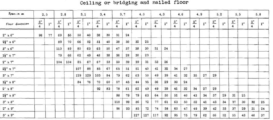
Appendix I I
Table for Floor-Joist Systems Distance be tween the jOist in em
Basis: 6% dissatisfied, y
=
0.87 mm, Efloor=
120,000 kg/cm2Ceiling or bridging and nailed floor
Spa"in '" 2,5 2.8 3.1 3.4 3,7 4,0 4,3 4.6 4.9 5.2 5.5 5.8 5" 5" 1.: セ 5" £
I" 5" セ L £ 5" .§::
Floo.- di",ensio n I" I" I" I" I" - I" I" I" I" I" I"
4 4 4 4 4 4 4 4 4 4 4 4 2"X6" 98 77 69 55 50 40 38 30 31 24 21" X6" 89 70 66 52 51 40 38 30 32 25 3" X6" 113 89 80 63 63 50 47 37 38 30 31 24 li" X 7" 79 66 62 49 48 38 36 28 30 23 I 2" X7" 104 104 85 67 67 53 50 39 39 31 33 26 21" X 7" 107 88 85 67 65 51 51 40 41 32 34 27 3" X7" 129 129 103 84 79 62 63 50 49 39 41 32 35 27 29 II"X 8" 84 76 70 60 57 45 44 35 36 29 30 24 2" X 8" I 92 83 78 61 62 49 49 39 41 32 34 27 29 21" X8" 98 79 79 63 64 50 51 40 43 34 37 29 31 25 3" X8" 118 99 86 72 77 61 63 50 52 41 43 34 37 30 32 25 -2" X9" 98 93 85 72 74 58 60 47 49 39 42 33 37 29 31 24 3" X9" 127 127 117 92 95 75 79 62 66 52 55 43 46 37 I N If.l>. I
MMMMセセMMMセセMMMN⦅セMセ
.
Table I
Distribution of the quality ratings put down for the test joist floor
Nurnbe r- of opin i on s
f'
Span in kves» be Comout.ed deflection
t
forLoad
3atis- Dcubt- Uns ati s- rating
m Total
fa r:tory ful factory q = 210 kg/m2 p= 150 kg/m 2
4.67 70 (63) 1 24 (18) 45 (44) 2.73 (2,68) 1/198 1/277 5,th 4,34 53 3 16 34 2,59 1/247 1/346 ro 4.07 36 (33) 1 (0) 11 (9) 24 2,64 (2. 73) 1/298 1/417 land 3.77 47 (38) 11 (7) 27 (22) 9 1,95 (2.05) 1/375 1/525 2.98 8 7 1 1,13 1/760 1/1065 '-'ith 3,77 36 (25) 4 (1) 21 (16) 11 (8) 2,19 (2,28) 1/375 1/525 load 4.07 57 3 27 27 2,42 1/298 1/417 600 kg 1 3 2, '15 1/247 1/346 4,34 4
In some of the tests children have been
included in the total numbers. In such
cases the number of adults is given in
par-an t he se s ,
The deflections have been
computed for I
=
3360 cm3 and E=
100,000 kg/cm2 I l\) (J'l I--J
Table IIResult of 、・ヲャセ」エQッョ measurements and ratings in the 1nvestigation in completed houses
セヲGZ]v
Deflect10n f 1n mm 0.38 \1.00 OAl 0.68 1 all 5 1 10.83 0.48 0.49 0.70 1.12 0.88 0.85 0.4711.01 0,4 8 0.57 0.5711.81 0.60 0.83 p.2651 0.57 0.31 0.28 I 0.53!0.99 0.66 0.66 0.41I
O.91 0.41 0.36 0.43 0.78 0.41 0.38 0.38 0.77 0.39,0.35 I N (J) I 1/312 1/245 1/434 1/420 1/550 1/238 1/337 1/267 1/267 d・ヲャX」エゥッセ eocoro mg to s oc o I» fica Hans f T 7.78 8.16 2.3 5.34 4.1a
4.76 4.76 3.25 5.18 Compu'beddeflec-tion in rom due to
a concentroted load af 100 kg セ f : Tセ E'r·10 5000 5000 3330 3330 1410 5000 1725 2380 3330 3330 3'x8" 60 3"x8" 60 .. 60 60
セ
!f..
J=7n
1 1 1 1 -Joists .5pac.ing
I
I C,.m I -"_ S irtl1"'1 Sl.lpported SiMpl '( Sl.lpported 460 - 1 1 - 498 Cantゥャ|ャNHdャHLセ 445 2"xff 498 t'x8" 380 txs" I 60 II " I 380 3x8 I 60 354 68x 145 55 360 66x163 55 423Rセx
8::I
6a
423 2)(8 60 3 I 2a 2 1I
1 11.66 1.33 3 1 1.44 1.22 1 2.33 2.33 2.33 2 1.0 2.66 1.83 3 2.33 3.0I
2.67 2 1.16 1.00 1.08 2 2.33 1.5 1.92 2 1.67 1.67 1.67 3 1.56 1.33 1.44 3 1.77 1.11 1.44 No.I
Rat1ng o f 'l
I
tests HOlASe-1 NB I wif.e.! L'oOl1 1
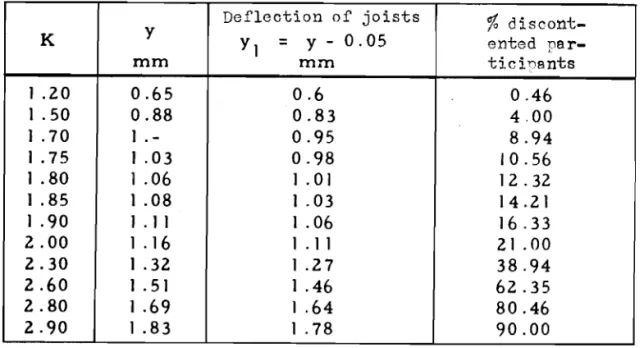
-27-Table III
Relationship between quality rating, deflection and percentage of discontented participants
Deflection of joists
%
discont-K y Yl = Y - 0.05 outed per-mm mm ticinants 1 .20 0.65 0.6 0.46 1 .50 0.88 0.83 4.00 ] .70 ]
.-
0.95 8.94 ] .75 1.03 0.98 10.56 1.80 1.06 ] .01 12.32 ] .85 1 .08 1 .03 14.21 1.90 1 .11 1 .06 16.33 2.00 1.16 1 .11 21.00 2.30 1 .32 1.27 38.94 2.60 1 .51 1 .46 62.35 2.80 1.69 1.64 80.46 2.90 1.83 1 .78 90.001
-28-Building regulat1ons: Housing Directorate:1:.
<.l.
1 200 f < 1 1 300.Swed1sh and Danish regulat1ons:
-f 1
1 <
5"00
Canadian regulations:
i
<SセP
Fig. 1
Comparison of the deflection requirements of joist floors in d1fferent countr1es
-29-The st1ffness of jo1st floors 1s computed
on the bas1s of a load of 150 kg/cm2
. , t - - - , Bu11d1ng regulations: Housing Directorate:
1:
<_1_ I 280 f 1 1 < 420Swedish and Danish regulat1ons: f1 <
500
1"Ganad1an regulations:
Fig. 2
Comparison of the deflection requirements in different
-30-Aesthetic
Cracks in the wall, etc.
Practical
Fig. 3
Vibrations
-31-100LMMMMMMMLMMMMLMMMMMMMMLMMMMセMMセMMMMMLLMMMMイ⦅⦅M⦅⦅L 50 ·30 (,I
"..,
<, セ 20 <::; e-I セg
10"
2-
lmper-Lt:
Ctptible5
3 35
/0 20 50 100 200 Amplitude in '//000mm
Fig. 4 500 1000Personal reaction to undampAd oscillations (according to Building B.eseareh Station Digest No. 78)
-32-1----
60 ./\Jmm
&)'fsl(tlI b,Mc!Sectio:1 throu)1 tho ェッゥgエMヲャッッセ セySエ・ュ with floor, 「イゥ、セャョァ and CGlllllS
Fig. 5
Test ,joist-floor system with floor, hridging and ceiling
LQcld we.ights ャP「GGGセ ...rood
---4-+--_1/4 ---o--r--- 1/4
___to-+---" - - - / - 480
- - - 1Fig. 6
Setup for measuring the deformations of the joist floor. Lead weights serve as the load
-33-5
--- joists with bridging framo with floating floor --.---- frame with floating floor
and bridging
frame with nailed floor and bridging
__ 0_-
frame with nailed floor Bnd no bridging---._ .. _. frame vrith nailed floor, 「イゥ、セゥョァ and ceiling 4
,
I I I,
,
,
,
,
"\,
I \, ,I \,. ,, \, ,I \ , \ I V \ \ \ \ \ \ \ I uャMMMMMKMMMMM]NNMMMMMNZセエ⦅i⦅⦅MゥMMM-s51r---...:....-_ _
s:l o .r!t
1,5イMMMMMセJGMMMMMZNセ⦅⦅⦅⦅Z⦅ZZセM⦅KM⦅⦅ZZZZM]M]K⦅⦅⦅⦅⦅[[スl⦅ャ⦅⦅MMMMMM⦅⦅j (l) r-l G-i (l) セ zNPイMMMMMMKMセセB⦅_⦅セセセセlM⦅Z⦅ Fig. 7Deflection of a test floor (measured at the centre) when a
concen-trated load of 128.18 kg is applied at the centre
A
セMMMMM
x ...
l
---lJ
Fig. 8
Force assumed to be exerted by the 'floor boards on the individual jOists
Brick wall I I / I / I / / / / / / I / I / / / I I I I I I I / I I / / /
r
1-( Rag rug
I
I
,
Span -34-Tableo
/
セi
Frame wall ャセB xIt"
lath floor Frame wall«
Fig. 9Joist floor under sUbjective testing. The frame walls were p-rected
3,0
3,0
xx2,5
IHMIHセ .X 2,0 Average rating 1,5/,5
-35-ojNNNNNMMセZZZZZZZZZNNNNNMMMMャMMMMMMl ---L. _J/,0
/00
r - - - . - - - _ r - - - - _ r - - - , tt:I セ 80 セ ro 0-..-f C) ... セ 60 セ ro 0-ro Q) ... セ'10
tt:I ..-i セ m tt:I tt:I ..-f ro 20 セ セ 100 .0 ::s 0 ro 80 セ ..-i_ N 60 tt:Iセセ
roorl /fa ーLセ ..-i(,'j C) セ ..-f-20 セ セ ro P-o
セ 1,0 2,0 2,5 Average rating Fig. 10Graph showrng the relationship between the average rating and the
percentage of participants who put down rating 2
Fig. 11
Graph showing relationship between the average rating and the percentage of participants who put down rating 3 (i.e., those
fャァセ 12
Vibrations of a joist floor when an object weighing 5 kg is dropped
On it from a height of 45 em"" The joist-floor system consists of
5 jOists,
floor
and bridging..The
span is 3 ... 77 eM" The floor lISnot SUbjected to a load
Vibrations
ot
S joist floor when an object welghing 5 kg 1s droppedon it from a help.;ht
or
45 om.. The jOist-floor system consists of5 jOists; floor and. bridging.. The span 1s 3",77 m... The floor is
-37-Fig. 14
Set-up for measuring deflections of residential joist floors
Fig. 15
-38-CJ.
Pi
Fig. 16
Symbol used in equation (7)
3r----r----r----r---r--===..,...-0-j
/,75
- - x -/,5 セᆳ-x - - -
NBt
e Housewife /,25 x x0,75
I
/ ---<i>"'="---'--)(- - - ) 0 ( .l....- ----I. --l...._...10,50
/,00
セ
;i
2
イMMMMMMMMKMMMMMMKMMセセセMMiMMMMMMMエ⦅⦅MMM⦅⦅KNM⦅⦅⦅ェ セ CdDeflection in mm due to a concentrated load of 100 kg
Fig. 17
Relationship between the ratings for the floor quality and
39
-..
Amer1can 1nvest1gat1on
nッイセ・ァQ。ョ 1nvest1?at1on
Steel-jo1st floor (Amer1can 1nvest1gat1on)
2,0 1,5 I,D CI.l セ /00 a3 p. ..-4 o ..-4 75 / +:I / M a3 P.
..
'd 50 (\) .p s:: (\) .p s:: 25 0 o CI.l ..-4 'd セolMMMGZZZZZB]BB _ _....l..- ---J.. ---=-, 0.5Deflect10n 1n mm due to a concentrated load of 100 kg
F1g. 18
Compar1son of the Norweg1an 1nvest1gat1ons w1th the Amer1can