Publisher’s version / Version de l'éditeur:
Canadian Geotechnical Journal, 1, 1, pp. 43-51, 1963-09
READ THESE TERMS AND CONDITIONS CAREFULLY BEFORE USING THIS WEBSITE.
https://nrc-publications.canada.ca/eng/copyright
Vous avez des questions? Nous pouvons vous aider. Pour communiquer directement avec un auteur, consultez la
première page de la revue dans laquelle son article a été publié afin de trouver ses coordonnées. Si vous n’arrivez pas à les repérer, communiquez avec nous à PublicationsArchive-ArchivesPublications@nrc-cnrc.gc.ca.
Questions? Contact the NRC Publications Archive team at
PublicationsArchive-ArchivesPublications@nrc-cnrc.gc.ca. If you wish to email the authors directly, please see the first page of the publication for their contact information.
NRC Publications Archive
Archives des publications du CNRC
This publication could be one of several versions: author’s original, accepted manuscript or the publisher’s version. / La version de cette publication peut être l’une des suivantes : la version prépublication de l’auteur, la version acceptée du manuscrit ou la version de l’éditeur.
Access and use of this website and the material on it are subject to the Terms and Conditions set forth at
The modulus of elasticity of leda clay from field measurements
Bozozuk, M.
https://publications-cnrc.canada.ca/fra/droits
L’accès à ce site Web et l’utilisation de son contenu sont assujettis aux conditions présentées dans le site LISEZ CES CONDITIONS ATTENTIVEMENT AVANT D’UTILISER CE SITE WEB.
NRC Publications Record / Notice d'Archives des publications de CNRC: https://nrc-publications.canada.ca/eng/view/object/?id=b47f7479-c1d9-409b-b0fa-60e9c2f4324a https://publications-cnrc.canada.ca/fra/voir/objet/?id=b47f7479-c1d9-409b-b0fa-60e9c2f4324a
THIS publication is being distributed by the Division of Building Research of the National Research Council. I t should not be reproduced in whole or in part, without permission of the original publisher. The Division would be glad to be of assistance in obtaining such permission.
Publications of the Division of Building Research may be obtained by mailing the appro- priate remittance (a Bank, Express, or Post Office Money Order or a cheque made payable a t par in Ottawa, to the Receiver General of Canada, credit National Research Council) to the National Research Council, Ottawa. Stamps are not acceptable.
A coupon system has been introduced to make payments for publications relatively simple. Coupons are available in denominations of 5,25 and 50 cents, and may be obtained by making a remittance as indicated above. These coupons may be used for the purchase of all National Research Council publications including specifications of the Canadian Government Specifi- cations Board.
Reprinted from Cnnndinrt Geotcchnicul Jounzal, Vol. I , No. 1, Sept. 1963
THE MODULUS OF ELASTICITY OF LEDA CLAY
FROM FIELD MEASUREMENTS
'I'he construction of the Ottawa Sewage Treatment Plant provided a n opportunity t o measure hottotn heave in two large excava- tions in clay. With gauges installed prior t o excavation, elastic heave, swellilzg, and heave due t o pile driving were measured in a n excavation 31.5 ft. deep. Using a Poisson's ratio of 0.4, the modulus of elasticitv deter- mined fro111 field measurements compared favourablv with the initial t a t l ~ e n t
-
modulus from the best unconfined conlpression strength tests. In the other excavation a drow in the ground water table produced a n elastic settle- ment that exceeded the elastic heave resultincr ',from u~lloading by excavation.
La construction d'une usine d'Cp~tration des eaux B Ottawa nous a fourni urle occasio~i de mesurer les soul&vements d u fond de dells fouilles d'importarlce d a r ~ s l'argile LCda. Avant le debut de l'Cxcavation, des jauges furent itlstallCes pour rnesirrer le svul&vement dii B la dCforrnation Clastique, au gonfletnent e t au battage des pieux at1 fond d'une fouille de 31.5 pieds de profondeur. Le module d'elasticitk calculC A partir des mesures sur le terrain e t du coefficient de Poisson de 0.4
est colnparable au module dotlnC par la tangent B la partie ir~itiale de la courbe con- trainte-dCformatio obtenue par les nleillerrrs essais en corrl~ressio~l simwle. Dans I'autre fouille, un affaissement de la nappe phrCatique a produit 1111 tassement 4lastique de plus
grande amplitude que le soul&verr~ent dil A I'excavation.
When a soil is unloacled rapiclly by excavation it r e b o ~ ~ n d s elastically. Re- loading produces an elastic settlelnent of equal magnitude, and if greater loads are applied, additional settlement due to consolidation of the subsoil may occur. Elastic tnovenlcnts may be unimportant for many sliallow excava- tions, but for deep excavatioris such as for basements of large t~uildings elastic rebound and subsequent elastic settlement may cause serious difficulties. I t is often not possible to predict accurately the elastic movements because it is verjr difticult to Ineasure the ~ l ~ o d u l u s of elasticity E for a soil material. The moduli deternlined from unconfined conlpressioll tests on undisturbed tube samples are usually much too low and field measurements are difficult t o make.
The constructiorl of the Ottawa Sewer Plant, with an initial capacity of
40 million gallons per day (mgd), was started in 1961. When conlpleted in 1963, it will provide primary treatment of the 25 mgd of raw sewage now emptying into the Ottawa River through twenty-three separate outlets. When necessary, its capacity can be increased t o
7,5
nlgd to serve an ultimate population of 590,000. The design and constructioll details have been puh- lished by MacLaren et a,?. (1960). Large excavatiorls were necessary for the constructiori of the main pumphouse of the plant, the digestor tanks, and the primary settling tanks. 'The Division of Building Research of the National*Research Officer, Soil Mechanics Sectiotl, Division of Building Research, National Research Council, Canada.
Research Council of Canada took the opportunity to Irieasure bottoill heave it1 two of the large excavations.
The sewer plant is situated on the eastern outskirts of the city of Ottawa on 320 acres of flat clay plain about 40 ft. above the Ottawa River (mean water elevation 134). The subsoils are lacustrine and rriarine clay (Gadd,
1963) : stiff, fissured, brown-grey to a depth of 20 ft. ; stiff grey clay to 50 ft. ;
becoming black-mottled and very silty to a depth of 86 ft., where glacial till is fourid. Grey limestone bedrock is a t a depth oi 96 ft.
Excavatioris for the three digestion tanks and the priniary settling tanks are shown in Figure 1. For the digestion taxiks the excavatiorl was roughly
--- PROPOSED LOCATION OF STRUCTURES
-
L I M I T S OF EXCAVATIOU HEAVE GAUGES0 50 I00 200
SCALE IN FEET
O DEEP BENCH MARKS O DBY
( A ) D I G E S T I O N TANKS ( 0 ) PRIMARY SETTLING TANKS
FIGURE 1. Location of heave gauges in excn\~atiolls for digestiori and pri~nary settling t a n k s
L-shaped, with each leg about 320 ft. by 190 ft. by 31.5 ft. deep. For the primary settling tanks it was rectangular with sides 330 ft. by 240 ft. The depth varied, increasing frorn 12 ft. a t the north and south ends to 21 ft. in the trench a t the centreline. I t was therefore possible to measure bottom heave i n two excavations of different depths.
During excavation for the main pumphouse il~imediately north of the other cxcavations, large undisturbed block sarnples of soil were obtained a t regular intervals for laboratory tests. These samples indicated a preconsolidation of niore than 3 kg./sq. cm. (Crawford, 1961). The liquid limits of the material vary froni 70 to 50, with the natural water content usually much higher. Grain size analyses indicated that GO to 70 per cent of the soil particles were in the
clay size range. Thc soils are very sensitive, have a high initial void ratio, and liquidity indices between 1 and 3. Six unconfi~leil compressio~l tests performed on specimetis tri~nrned from each undisturbed block sanlple produced shear strengths of 1.5 kg./sq. cni. For the initial tangent n~odulus the highest value from the ~lrlconfined tests on each block was used, A sum1n;irj- of the test results and a soil profile is plotted in Figure 2.
At the excavation for the digestion tanks initial instrumeiitntio~i corisistetl of three sets of heave gauges, installed to depths of 15 ft. and 31.5 ft. below the ground surface, and a deep bench illal-I<. Unfortutlately, the 15 ft. gxuges were lost during excavation without any possibility of their t~eing rend. Four heave gauges and a deep bench mrtrk were also installed a t t h c site of the primary settling tanks. The depths of the gauges a t statiorls (12
+
471, (13+
OO), (13-I-
05), (13+
10) were 14.5ft., 13.5ft., 17.5ft., and 23.5ft. respectively. The locations of the heave gauges and bench mnrl;s are shown in Figure 1. The purpose of this arrangement of gauges was to ol~serve tlie bottolil heave near the edge and towards the iniddle of the excavntions.The heave gauges were patterned after thosc used in Norwaj. (Norivcgian Geotechnical Institute, 1962). They consist of four 0.25 in. thicl; steel lins welded together to form a vane 3.5 in. diameter and 13 in. long supporting a 0.7.5 in. thick plate as dctailed in Figure 3. -4 slotted lie, hole was prepnrecl in the centre of the plate to facilitate install (1 t ' 1011.
CLAYEY SOIL CAVATION I I
BENTONITE GEL, WITH ERYTHROSI DYE, COLOUR IND
HEAVE GAUGE D E T A I L OF STEEL HEAVE GAUGE
FIG. 3. Details and installations of heave garlge
The heave gauges were lowered with drill rods dowri a clean augcred 4 in. diameter boreholc and forced into the undisturbed soil. The rods were dis- engaged arid removed, leaving the gauge in place. The boreliole was then purnped full from the bottom with a bright red bentonite slurry that would gel (about 800 per cent water content and coloured with Erythrosine dye
Colour Index 773, Figurc 3). The bentonite gel protected the borehole froill caving and from filling from the top with loosr soil di~ring excavation, and the bright red colour assisted in locating boreholes while excavation was in progress. Readings on the gauges were rilade by souridirig through the gel arid taking ~izeasurenients to f 0.001 ft. with an engineer's precise level.
The deep bench 111arks consist of an iron pipe with a steel foot driven into the glacial till. The iron pipe, which is the reference point, is protected fro111 the surrounding soil by an oil-filled casing. Details of this iristrumentation and the installation procedure have been described by Bozozuk ct al. (1963).
FIELD
N~EASUIIEMENTSDigestiofe Tanks
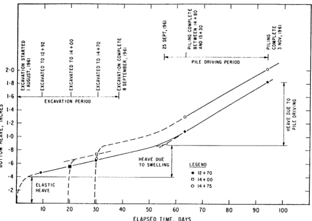
Excavation for the digestion tanks was started August 1, 1961. The con- tractor excavated unifornlly over the area with scrapers and pushers to a depth of 3 ft. to 4 ft., but this equiprilerit bogged down arid the excavation had to be conipleted with drag lines and shovels. As shown in Figure 1 the clrag lines excnvated to the full 31.5 ft. depth in one stage, starting a t the south~vest end and completing the excavation a t the north end 011 Scptenibcr 8. The floor was then covered with 1.5 ft. of crushed stone iill to provide a iirnl worliing base for construction equipment. Pile driving for the individual tanks coniine~iced a t the west end of the excavation on September 25 and was com- pleted over the site on Noveinber 3, 1961. An inceresting part of the pile- driving operation was the ease with which the piles were driven. Once they were positionecl arid tapped with the hamnler a couple of tinles they were pushed to the full depth of 50 ft. (the boom length of the pile driver) in one quick strolte.
Because of the method of excavation, it was impossible to obtain readings on I-he heave gauges a t various stages of unloading as had originally been planned. Readings were obtained onlj. after the excavation had heen coni- pleted over the various gauges.
As is shown in Figure 4, bottoni heave occi~rrecl in three stages: (i) instan- taneous or elastic heave, (ii) time-dependent heave or swelling, and (iii) heave due to pile driving. Elastic heave was least near the edge of the excavation, becoming grealer in the middle. As thc material was always fully satirrated (the water tnl~le was found in the crushed stone fill) swelling also took place. Before swelling was complete pile driving was begun and caused additional heaving. At tlie end of pile driving the total combined heave ranged fro111 1.8 in. a t the edge of the excavation to 2.0 i l l . a t the centre. About half of
this total coulcl be attributed to pile driving.
Primary Settling Tanks
The heave gauges a t the primary settling tanks were installed December 14,
1961. Excavation proceeded between January 23 and February 26, 1962. The top 5 ft. to (5 ft. were removed by scrapers; because of freezing temperatures the contractor was forced to rip the frozen soil so that thc scrapers could be push loaded. Finally drag lines were used to conlplete the job.
A
1.5 ft. layer of crushed stone fill was then placed on the floor of the excavation.I I I I I I I I I I W o L m - J + rO E $ ? t- a s z f w - L'z W W gg5' - 2 - 0 C "7 ; c a 5 - 5 8 o + h O W 0 - w z ? : Z &
:
J - + - w N a m < L U C ) 4 N x r d Z ? r n ~0 0 -- . ~ . - 'C t- 0 + S =- PILE ORlVlNG PERIOD -4
$ " n a w o Z W 2.0 -;; W o m c a m u a > u C > $ 2 1.8
-$$
5
u x v a x =-E x 3~ Y - W w W x w m " 1.6 --A L . 14
EXCAVATION PERIOD V) y 1.4 - U a w ,A, n9
1.2 - / > w 4-1 - W 2 1.0 - W X - '8 - I- - I- HEAVE DUE P '6 - LEGEND - A* I 12 t 7 0 * 4 - / 5 -1 1 0 1 4 t O O - / E L A S T I C I I 0 14 t 7 5 '2 t HEAVE I I-
I 11 11 I I I I I I I 10 20 30 40 50 60 70 8 0 90 100ELAPSED TIME, DAYS
F I C ; U K L ~ 4. Bottoin heave in 31.5-ft. deep excavatio~~ for digesliori tanks
I I I - 6
-
- v, - 4 - -. W I"
.2-
f 0-
-
- - 0 OF-. 0-0-0-
- - - u,
--
- 0 - 0 - 0 W rl I-
.2-
\ \ m'
.
a# -I - 0 I- -.4 - J.2 I- - 0 43 - - 6 - - W D - - 8 - 0 12 t 47 AT D E P T H 14.5 F T - 13+
10 AT D E P T H 23.5 F T +- LL q 13 t 0 5 AT D E P T H 17.5 F T I 3 t 00 AT D E P T H 13.5 F TE X C A V A T I O N ABOVE HEAVE GAUGES
CRUSHED S T O N E F I L L -
v//////////////Y/////////////,
+--
a JUST E A S T OF H E A V E GAUGES W I I 1 0 50 100 150 200 ELAPSED T I M E , DAYSSatisfactory measurements on the heave gauges were difficult to obtain. A t
the start of excavation the contractor chose to use the area where the deep bench mark was located as a spoil area for stockpiling the excavated soil. A
large concrete foundation for one of the nearby structures was therefore used as a refererice datum, but it soon became evident that it was not stable, probably because of frost action. When the frost disappeared in the spring, it was possible to locate the original bench rnark and use i t for the final survey. This indicated that a small net settlement had occurred at the 23.5 ft. gauge. All preceding surveys in which the concrete forrndation had been used as a datum were referenced, therefore, to the 23.5 ft. gauge and the results plotted in Figure 5 .
A srrlall heave of about 0.1 in. occurred a t the edge of the excavation. 'To- wards the centre, the botto~n settled about 0.3 in. initially, reducing to 0.15 in.
with subsecltrent swelling of the soil. Lowering of the ground water table, caused by pumping from the adjacent 31.5 ft. excavation and drainage from the 21 ft. cleel:, trench, apparently caused an elastic settlelllent that exceeded the elastic heavc due to unloading.
The elastic. settlemelit of the corner of a rectangular uniformly-loadecl area located a t the ground surface was given by Steinbrentler (1934) and Tet-zaghi (19-23) :
where p
-
elastic settlementp = surc:harge
B = width of loaded area
E = elastic ~nodulus
I, = influence factor which depends upon size and shape of the loaded
nr-e;~, Poissorl's ratio (,u) ancl depth of con~pressible soil. The influence factor, I,, tnaj7 be obtained from :
where
F1
and Fg are co~lstants that rnay be obtained from the graphs given bjr Steinbreriner (1934) or Terzaghi (1943).The modulus of elasticity rnay be determined from heave measurements 1)y re-arranging equation (1) into the form:
where p = elastic heave
q = amount of unloading.
calculated from the original surface of the ground and corrected for the depth of the excavation. The depth of soil subject to elastic heave would increase from the edge of the excavation toward the centre. Assuming that this "depth" increased linearly from the toe of the slope by 45", the heave gauges a t
(1 2
+
70) and (14+
00) would be affected by the edge of the excavation. A t(14
+
75) the gauge was 66 ft. from the toe of the slope. Consequently, thedepth of soil subject to elastic heave was limited by the depth of clay over- lying the glacial till a t this location, 55 ft.
The modulus of elasticity a t (14
+
75) was calculated for Poisson's ratiosof 0.3, 0.4, and 0.5 and summarized in Table
I.
For comparison, the averageinitial tangent modulus of elasticity El for the soil profile, obtained from
laboratory strength tests, was also included. The laboratory value for El of
750 kg./sq. cm. compared favourably with the field results of 720 kg./sq. cm. for a Poisson's ratio of 0.4.
TABLE I
Summary of Calculations: Modulus of Elasticity Determined from Heave Measurements it) Excavation for Digestion Tanks
E = Modulus of Elasticity, kg/sq. cm.
Location - .-
p = 0 . 3 p = 0 . 4 p = 0 . 5 El*
14
+
75 822 720 59 1 753*Average maximunl initial tangent modr~lus for the soil profile, obtained from the best unconfined strength tests on specimens trimmed from large undisturbed block samples.
Field measurements of bottom heave a t the primary settling tanks showed that a net settlement occurred in the nliddle of the excavation; this was
attributed to a lowering of the ground water table. [Jsing an E value of
720 kg./sq. cm. measured in the deep excavation, the elastic settlement due
to a drop in ground water table of 28 f t. and the elastic heave due to unloading
were calculated for Poisson's ratios of 0.3, 0.4, and 0.5. The results given in
'Table
I1
show that the calculated net settlement of 0.02 ft. for Poisson'sratios of 0.3 and 0.4 is very close to the measured value of 0.03 ft.
'TABLE 11
Compariso~l of Measured with Calculated Bottoin Heave in the Excavation for the Primary Settling Tanks
p , due t o drop in p , due to P
E ground water table, unloading, Net p , Measured,
kg/sq. cm. P ft. ft. ft. ft.
From the measurements in these excavations, the Poisson's ratio for Leda clay appears to be 0.4 or slightly less. I t substantiates the use of this value
for estimating elastic settlements of buildings in Ottawa (Legget et al., 1961)
and supports arguments against the arbitrary assunlptio~~ that the Poisson's
ratio for saturated soils is 0.5 (Crawford and Burn, 1963). A more realistic value for Poisson's ratio of saturated soils may be between 0.3 and 0.4.
The observations also show that elastic heave may be compensated by elastic settlement due to a lowering of the ground water table (Serota and Jennings, 1959).
The bottom heave in ari excavation 31.5 ft. deep in Leda clay near Ottawa occurred in three stages;
( a )
instantaneous elastic heave; ( b ) heave due to swelling with time; and ( c ) heave d u e to pile driving (this accounted for one- half the total heave).Field measurements of the modulus of elasticity, E, with a Poisson's ratio
of 0.4 compared with the best values of initial tangent modulus
El
obtainedfrom unconfined laboratory strength tests on specimens tritnmed from large undisturbed block samples.
The elastic settlements resulting from lowering the ground water table exceeded the elastic heave due to unloading the soil. This caused a net settle- ment in the bottom of the excavation for the primary settling tanks, as is shown by field measurements and verified by calculations.
This investigation was carried out with the co-operation of the city of Ottawa, the con- sultants (James F. MacLaren and Associates), and the general contractor (D. L. Jones Con- struction Company). The author wishes to express his sincere appreciation to all concerned for their valued assistance in this study. Thanks are also due to I<. N. Burn, who assisted in the instrumentation, and to C. B. Crawford, Head of the Soil Mechanics Section, for his encouragement and direction in the study. The paper is a contribution from the Division of Building Research and is presented with the approval of R. F. Legget, Director of the Division.
B o z o z u ~ , M., JOHNSTON, G. H., and HAMILTON, J. J., 196'3. "Deep Bench Marks in Clay
and Permafrost Areas." In press.
CRAWFORD, C. 13., 1961. "Engineering Studies of Leda Clay." Soils i n Canada (Toronto:
University of Toronto Press), 200-17.
CRAWFORD, C. B., and BURN, K. N., 1963. Discussion of "Settlement Studies on the Mount Sinai Hospital, Toronto." Engineering Journal 46: no. 5.
GADD, N. R., 1963. "Surficial Geology of Ottawa Map-Area, Ontario and Quebec." Canada,
Department of Mines and Technical Surveys, Geological Survey, Paper 62-16: 1-4. LEGGET, R. F., BURN, I<. N., and B o z o z u ~ , M., 1961. "Three Buildings on 'Floating Founda-
tions' in Ottawa, Canada." Journal of the National Buildings Organization 6: 106-19. Reprinted in Cunadian Consulting Engineer 4: 48-54.
MACLAREN, J. W., PAPPAS, N. D., and CLEMENT, D. B., 1960. "A Deep Pumping Station
for the Ottawa Sewage Treatment Plant." Engineering Journal 43: 56-63.
Norwegian Geotechnical Institute, 1962. Measurements at a Strutted Excavation, Oslo Sub-
way, Vaterland 1 , km. 1373. (Oslo, Norway, Technical Report no. 6 . )
SEROTA, S., and JENNINGS, R. A. J., 1959. "The Elastic Heave of the Bottom of Excava- tions." Gtotechnique 9: 62-70.
1
STEINBRENNER, W., 1934. "Tafeln zur Setzungsberechnung" (Tables for the calculation of