HAL Id: hal-00361665
https://hal.archives-ouvertes.fr/hal-00361665
Submitted on 8 Feb 2013HAL is a multi-disciplinary open access
archive for the deposit and dissemination of sci-entific research documents, whether they are pub-lished or not. The documents may come from teaching and research institutions in France or abroad, or from public or private research centers.
L’archive ouverte pluridisciplinaire HAL, est destinée au dépôt et à la diffusion de documents scientifiques de niveau recherche, publiés ou non, émanant des établissements d’enseignement et de recherche français ou étrangers, des laboratoires publics ou privés.
Experimental response and vibrational characteristics of
a slotted rotor
Jean-Jacques Sinou
To cite this version:
Jean-Jacques Sinou. Experimental response and vibrational characteristics of a slotted rotor. Com-munications in Nonlinear Science and Numerical Simulation, Elsevier, 2009, 14, pp.3179-3194. �10.1016/j.cnsns.2008.10.024�. �hal-00361665�
Experimental response and vibrational characteristics of a
slotted rotor
J-J. Sinou
Laboratoire de Tribologie et Dynamique des Syst`emes UMR CNRS 5513 Ecole Centrale de Lyon, 36 avenue Guy de Collongue, 69134 Ecully Cedex, France.
Abstract
This paper proposes to perform experimental tests on the vibrational characteristics of a slotted rotor. Changes in the responses of then× amplitudes are examined for small and deep slots that
can be considered as open cracks. The evolutions of the orbital patterns and the 2× harmonic components near one-half of the first critical speed are investigated in details to propose an efficient indicator of the presence of slots in rotor: a special attention is given to both the com-parison of the horizontal and vertical maximum amplitudes of the2× harmonic components, and changes in the size of the inside loop of orbits when the rotor is passing through one-half of the first critical speed.
A huge experimental work considering the influences of the slot depth and the orientation of unbalance relative to the slot direction is investigated in order to examine the possibility of detecting the presence of a transverse slot in rotors.
1
Introduction
Dynamic behavior of cracked rotors has been a subject of substantial interest for the last three decades. Reviews on cracked rotors and structures can be found in [1–3]. Most of the previous studies focused on detecting cracks in rotor by means of the observation of the lateral non-linear rotor’s steady-state vibrations using only numerically analysis [4–7]. They indicated that the presence of a crack induces changes in the2× and 3× harmonic components of steady-state response of the rotor system. They also proposed to exploit the evolutions of orbital pattern of the cracked rotor at one-half of the first critical speed for the non-destructive detection of cracks in rotors.
More recently, several researchers have studied the dynamic response of cracked rotors com-bining theoretical and experimental approaches. Generally, experimental tests are undertaken in order to illustrate the efficiency of the proposed methodologies and on-line diagnostic tech-niques. For example, Seibold and Weiner [8] proposed a time domain identification algorithm based on the Extended Kalman Filter for the localization of cracks in rotating machinery. Ex-perimental and numerical investigations on the response of the cracked rotor to periodic axial excitation were carried out by Darpe [9] to prove that coupling of bending and longitudinal vi-brations may be used as the signature of a transverse crack in rotors. Bachschmid et al. [10–12] proposed a model-based diagnostic approach with a least-squares identification for the detection
of cracks in rotors. The reliability of the proposed methodology was validated by experimental tests on industrial rotating machineries with an excellent accuracy obtained in identifying both the position and depth of cracks [12].
Finally, relatively less work is reported on a complete experimental study of the steady-state non-linear vibrations of a rotor with various crack depths. Exception are the works of Pennacchi et al. [12], Darpe et al. [13], Adewusi and Al-Bedoor [14] and Mayes and Davies [15, 16]. These works have been widely used by other researchers to validate their theoretical studies. These experimental studies showed that the steady-state vibration signal of a propagating crack produces changes in 1× and 2× amplitudes and induces the classical two-loops orbit at
one-half of the critical speed. Moreover, Adewusi and Al-Bedoor [14] noted that the3× amplitudes appear just before the rotor’s fracture. In these papers, the authors proposed to generate a real propagating transverse crack in the rotor.
In the following study, the type of crack that has been chosen is a slot (i.e. the crack always remains open). As indicated by Sabnavis et al. [3], cracks that are assumed to be open all the time are also known as gaping cracks or called “notches”. Even if this slot does not reproduce exactly the typical propagating and breathing behavior of a crack in rotors, it allows to show the effects of an always open crack due to the rotor stiffness unsymmetry introduced by the slot. For the following study, this type of crack reproduction has been chosen for two main reasons. Firstly the reproduction of a real propagating crack in a rotor is a very difficult and expensive work especially if a huge experimental work is required. As explained by Sabnavis et al. [3], most experimental work is focused on open cracks due to the fact that a slot is easy to mimic in a laboratory environment. Secondly, a transverse breathing crack is experimentally done by starting from a slot that allows to initiate a fatigue crack at the desired location. Then, the repeated experiment of cyclic loading cause the crack propagation as a consequence of fatigue solicitation [12,14]. For example, Mayes and Davies [15] decided to rotate the shaft slowly with a static load applied to the crack location. Darpe [13] proposed to place the rotor in a three-point-fatigue bending machine and to subject the shaft to cyclic loading. The disadvantage of this procedure is that the crack is firstly done in the shaft and then the complete rotor system is assembled. As explained by Pennachi et al. [12], this fact implies that it can be difficult to have a valid reference case of the healthy rotor: differences in alignment and unbalance can be introduced and so comparisons with the healthy rotor can be difficult. As explained by some researchers [12,15], the shaft is broken at the end of tests in order to reveal the fracture surface of the crack. Moreover, the initial slot and the propagating crack are both present in the shaft and so they influence the vibrational characteristic of the cracked rotor. Then, the shaft characteristics can be changed due to the cyclic loading used to create the crack and the appearance of a bow in rotor can be introduced. Thus comparisons of the vibration characteristics of the healthy rotor with those of the rotor with different cracks can be difficult to be done precisely. It can be noted that Mayes and Davies concluded in their study [15] that a horizontal cracked shaft, except for large crack where the depth is greater than the radius of the shaft, behaves as a slotted shaft with additional excitation due the crack breathing. They also indicated that their experimental results for a cracked rotor can be compared with the results obtained for an asymmetric shaft (based on the results of the experimental study of Taylor [17]). Numerical comparisons of the response of cracked and asymmetric rotors were also proposed by Henry and Okah-Avae
[18]: responses at the main critical speed and at one-half of the critical speed and the effect of eccentricity for both a linear asymmetry and a crack were studied. The authors indicated that the crack can tend to remain always open in the vicinity of the main critical speed due to the combined effect of eccentricity orientation and gravity. So, the shaft can behave like an asymmetric shaft if the eccentricity keeps the crack open. On the other hand, they also observed that the shaft behaves like a symmetric shaft if the eccentricity orientation is such to close the crack. The opening/closing phenomenon was also investigated by Jun et al. [19]. They performed an extensive numerical study of the necessary condition for a crack to remain always open or close, or to breathe. They indicated that opening and closing conditions are dependent upon the crack depth and unbalance. For example, they observed that the crack tends to breathe or to remain always open before the first critical speed if the unbalance and the crack are in the same direction. Above the first critical speed, the crack tends to remain always close. The opening/closing phenomenon is reversed if the unbalance coincides with the opposite direction of the crack. The authors indicated that the rotor tends to breathe when the direction of the unbalance is perpendicular to that of the crack (except near the critical speed). They also suggested that the crack tends to alternate the open and closed states when the unbalance becomes small. When the unbalance is relatively large, the crack tends to remain open or closed. Plaut et al. [20] also studied behavior of a cracked rotating shaft. They compared the responses of a shaft with a breathing crack to those for a crack that remains open and to those for an uncracked shaft. They demonstrated that the angle between the crack and the unbalance can induce significant changes in the responses of the rotor.
Finally, as suggested by Bachschmid et al. [21], different thermal states can force the crack to be always open. For example, Bachschmid et al. [21] explained that the thermal stresses tend to prevent and to reduce the breathing behavior for a heating transient (a positive temperature gradient). Moreover, if a cooling transient is observed (a negative temperature gradient), the crack can be always open. So the thermal states can drastically affect the breathing behavior.
So the limits of the experimental results that will be proposed in this paper concern the case of a slotted rotor, the vibrational behavior of a slotted rotor being sufficient to give the primary effects of the vibration changes for a rotor with an open crack. A complete study of the effect of different open crack depths, a complete comparison with the healthy rotor by considering the evolutions of thenth
orders (withn = 1, 2, . . . , 6) and the orbits (at the first critical speed
and at the n1 sub-critical resonant speeds) will be studied. The objective of this present study is to perform an huge experimental analysis of the effects of an open crack on the dynamic characteristics of rotors. Not only the evolutions of thenth
orders (forn = 1, ..., 6) as a function
of the rotating speed and the crack depths, but also interaction between the front open crack and the unbalance, and orbital evolutions will be discussed.
This paper is divided into three parts. Firstly, the experimental setup is presented. Then, the evolutions of the n× amplitudes and orbital evolution in the horizontal and vertical directions are investigated for the healthy and slotted rotors. Finally, the influence of the open crack depth and the interactions between the open crack and the unbalance parameters (intensity and orientation with the front crack) are undertaken.
2
Experimental setup
The equipment used for the experiment tests is composed of a Rotor Kit with a motor speed control and data acquisition interface unit that is controlled by the I-DEAS Software. The measured vibratory data are transmitted to a PC via the National Instruments PCI-4472 channel dynamic signal acquisition devices. Then the data are transferred from I-DEAS Software to Matlab in order to be examined and manipulated to obtain the n× amplitudes and the orbital pattern.
The picture of the experimental rig is shown in Figure 1. This test rig that consists of a steel shaft of480mm long and 10mm diameter, is simply supported at both ends by two bush
bearings. The experimental system is directly mounted on a rigid massive concrete table isolated from the environment. The left end of the rotor is coupled with an electric motor by means of a flexible coupling. The shaft carries one disc made of steel and placed at 382mm from the
left end of the shaft. Disc dimensions are75mm diameter and 35mm thickness. The disc has
sixteen holes that are separated by regular degree angle in order to be able to investigate the influence of the unbalance and angle between the front crack and imbalance intensity. Before the experimental tests, the level of the residual unbalance of the healthy rotor has been estimated
at0.18gm and 168deg.
The location of the open crack is at 243mm from left end of the rotor. The rotor’s cracks are made by cutting a piece of width0.2mm with a jeweler’s saw. Runs are done at five different
crack depths (from the small crack µ = 0.2 to depth equals to the half of the shaft diameter µ = 1, with intervals of non-dimensional crack depth δµ = 0.2) and with the uncracked rotor.
µ defines the non-dimensional crack depth and is given by µ = h
R where R is the radius of
the shaft andh the depth of the crack. Each cutting is realized on the complete rotor without
dismantling operations in order to be able to compare all the experimental tests with various crack depths. The cut introduces an open crack in the rotor. Indeed the lateral deflections being small, the slot may not completely close and would not eventually breathe. So the rotor under study may be considered as a slotted rotor (i.e. a rotor with an open crack) due to the cut which in turn may give different dynamic response from a rotor having a breathing crack. However, this experimental procedure has been chosen to be sure that changes in thenth
orders, the non-linear responses and the orbits are only due to the evolutions of the slot depth and not to structural modifications that may be introduced by dismantling operations.
To assess the non-linear dynamic of the cracked rotor and to investigate the effects of the presence of a transverse crack, the displacements of the shaft are measured in several transversal planes. Six non-contact displacement transducers that are mounted in both the horizontal and vertical directions are used in order to measure the displacement of the rotor. They consist of two orthogonal proximity probes for each plane and are placed at 70mm (plane A1), 210mm
(plane A2) and 440mm (plane A3) from the left end of the shaft. The position of the three
planes are given in Figure 1. Therefore, a tacho signal is used to measure the rotor speed that is measured and monitored at regular intervals during the tests. A variability of2.5rpm/s for the
Figure 1: Picture of the experimental rig and the transverse crack
3
Experimental results
The experimental procedure is divided into three parts. The first set of experiments are done for the healthy shaft. Secondly the evolutions of the non-linear behavior and then× associated
amplitudes of the slotted rotor are investigated by increasing the speed of the rotor (with a constant acceleration speed profile) until the first critical speed is reached. The effects due to the interactions between the open crack and the imbalance parameters (intensity and orientation with the front crack) are undertaken. Finally, the orbital evolutions are studied for various crack depths when the rotor passes through one-half and one-third of the first critical speed.
3.1
Healthy rotor
First of all, two cases are considered for the healthy rotor. The first case concerns the initial residual unbalance that has been estimated at0.18gm and 168deg. The second case corresponds
to the addition of an unbalance of1gm at 0deg.
An order tracking test (DSP method of filtering the measured time history signal) is performed to access the harmonic contents of the non-linear vibrations of the healthy rotor when the rotor runs from 0 to 4000rpm. Results of the n× amplitudes (n = 1, 2 and 3) and phases in plane A2 are presented in Figures 2 and 3 for the unbalance of0.18gm at 168deg, and 1gm at 0deg.,
respectively.
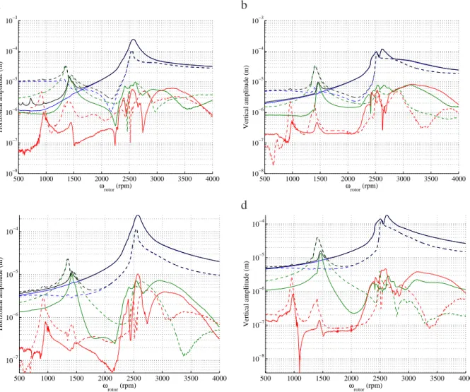
Some of the order tracking plots (the whole signal magnitude called the composite power, orders 1, 2 and 3) are presented in Figures 4 at the locations A1 and A3 in both the horizontal and vertical directions for the second unbalance case (i.e. 1gm at 0deg.).
The order 1 response peaks (Figures 2(a) and the blue lines in Figures 4) correspond to the first critical speeds of the healthy rotor. These figures show that the first rotor critical speed is around2500rpm.
From the phase evolution of the vertical and horizontal plots in Figure 2(a), the precession of the rotor is forward below 2700rpm and above 2800rpm: the vertical vibration leads the
horizontal vibration. Between2700rpm and 2800rpm, the rotor vibrates in reverse in the period
between the two principal resonances (i.e. the precession is reverse) and the horizontal vibration leads the vertical vibration. The simplest and predominant reason for this reverse orbiting is the asymmetric (i.e. anisotropic) support stiffness of the rotor system, as showing in the picture of the rotor system (see Figure 1). This is typically the case of most horizontal machines that are weaker horizontally.
From the 2× harmonic components in Figures 2(c), 3(c) and Figures 4, it can be inferred
the2× harmonic components are present. From the analysis of the 2× amplitudes in Figures 4,
the2× harmonic components are about 10 − 15µm for planes A1 and A3, and 25µm for plane
A2) at the 12 sub-critical resonances. The3× harmonic components appear to be very small for
the three planes in both the vertical and horizontal directions (with small peaks about1µm for
planes A1 and A3, and1.5µm for planes A2 when the rotor is passing through 1
3 of the first
critical speed). The presence of the2× component are typically due to the combination of the
asymmetry and a steady-state radial load that is generally due to the gravity on horizontal rotor. Then Figures 5 show the orbital evolutions of the healthy rotor at the middle of the shaft (plane A2) around one-half of the first critical speed, wherein a small distorted two-loop orbit is formed.
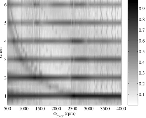
To clarify the presence of other orders than 1×, Figure 6 illustrates the evolutions of the n× amplitudes (forn = 0.25 − 6.25 with a step of 0.25). To compare the magnitudes of each order,
then× amplitudes are normalized on the speed range under study as follows:
Xnormalized = log (X) − log (X min)
log (Xmax) − log (Xmin)
(1) whereXminandXmaxdefine the minimum and maximum amplitudes of all then× amplitudes
on the speed range. Figure 6 shows that not only the second and third orders are present at the
1 2 and
1
3 sub-critical resonant speeds, respectively, but also the fourth, fifth and sixth orders at
the 14, 1 5 and
1
6 sub-critical resonant speeds, respectively. However, the 2×, 3×, 4×, 5×, 6×
amplitudes are small in comparison with the vibration amplitudes of first order. Finally, it can be also observed that thenth
orders (withn = 1, 2, . . . , 6) are present when the rotor speed reaches
the first critical speed, even if the associated amplitudes are not very significant in comparison with the first order of the non-linear response of the healthy rotor.
The small amount . that are mechanisms generating . components when the system behavior is non-linear. In fact, the presence of the bushings causes a non-linear response of the rig: super-harmonics are excited by synchronous excitations (like the residual or the additional unbalance) even without the presence of the slot. Thus the test-rig response is non-linear by itself and the effect of the slot is the combination of two non-linear responses. The non-linear response of the slot cannot be evaluated as simply additional to that of the rotor without the slot.
The small amount of super-harmonic components other than 1× can be attributed to the bow-related side load on the shaft-disk, and the rotor anisotropy and the unbalance that are mechanisms generating2× and 3× harmonic frequency components when the system behavior
is non-linear. In fact, the presence of the bushings causes a non-linear response of the rig: super-harmonics are excited by synchronous excitations (like the residual or the additional unbalance) even without the presence of the slot. Thus the test-rig response is non-linear by itself and the effect of the slot that will be studied in the following section of the paper is the combination of two non-linear responses. The non-linear response of the slot cannot be evaluated as simply additional to that of the rotor without the slot.
3.2
Slotted rotor
3.2.1 n× amplitudes
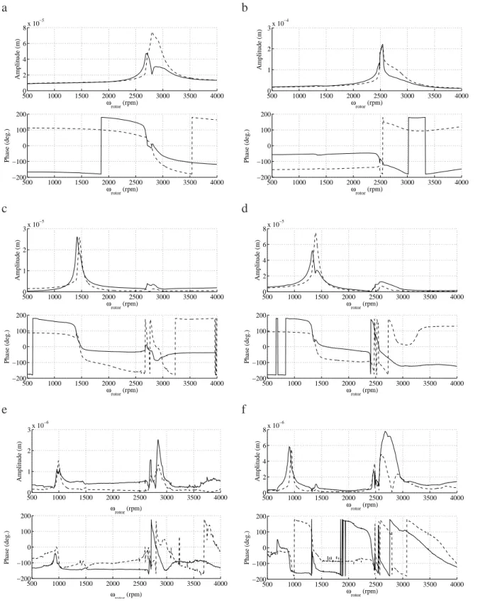
The effects of an open crack on the response curves of the rotor system are first considered in the present section. Figures 2 and 3 indicate changes of the1×, 2× and 3× amplitudes and phases for the healthy and slotted rotor in plane A2 (two unbalance configurations are given: the first case concerns the initial residual unbalance of 0.18gm at 168deg. and the second corresponds
to an added unbalance of1gm at 0deg). Then, Figures 4 show the evolutions of the non-linear
responses and the 1×, 2× and 3× amplitudes for both the healthy and slotted rotor at the
locations A1 and A3 for the second unbalance case (1gm at 0deg). In the case of the open
cracked rotor, the crack is situated at the middle of the shaft (as shown in Figure 1) and the non-dimensional crack depth is equal to 1, which corresponds to the case of half the area of the cross-section is missing due to the open crack.
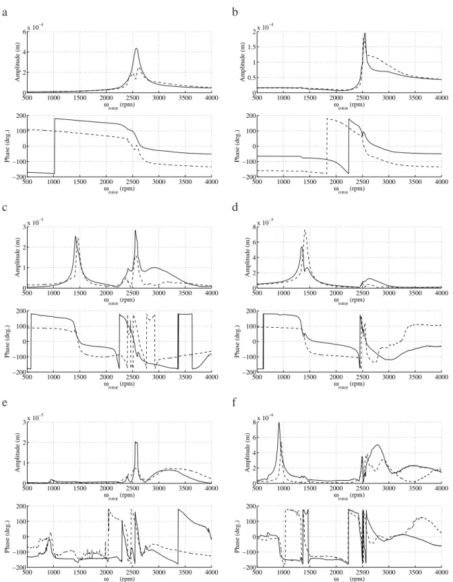
In regards to the1× amplitudes, an offset at very low rotating speeds is observed (see Figure 3(b) or Figures 4 (a) and (b) for example). This fact indicates a significant and permanent bow in the rotor. Then, the change in1× amplitudes at the first critical speed is clearly observed in all cases. From the analysis of the results for the initial residual unbalance (0.18gm at 168deg) in
Figures 2(a) and (b) for the plane A2, the vertical and horizontal synchronous amplitudes varies
from75µm and 48µm to 210µm and 220µm, respectively. With an added unbalance of 1gm
at0deg, the horizontal and vertical 1× amplitudes change from 440µm and 250µm to 200µm
and 180µm, respectively. Typically these changes in synchronous amplitudes are caused by
the shaft bowing due to the asymmetric transverse open crack. The bow is introduced by the slot and so the effect of the slot is equivalent of an additional unbalance. In our case, it can be observed that the offset due to this bow is important. For the slotted rotor, the bow generate around10µm and 15µm in the horizontal direction for the planes A1 and A2 (see Figures 4(a)
and (c) or Figure 3(b)).
Then, Figures 2, 3(c), and 4 illustrate the fact that the2× and 3× harmonic amplitudes for the
slotted rotor are more significant than that of the healthy rotor when the rotor reaches one-half and one-third of the first critical speed, respectively.
The high amplitudes of the peaks (about30 − 40µm for planes A1 and A3, and 55–75µm for
plane A2) at one-half of the first critical speed are clearly due to the open crack. Moreover, the resonance amplitudes of the3× components (about 3–5µm for planes A1 and A3, and 5–8µm
for plane A2) at one-third of the first critical speed, are recognisable. Even if the3× amplitudes are not very important, they are three times more important than for the healthy rotor and so clearly show the effect of the open crack.
The same conclusions can be done from the analysis of the2× and 3× amplitudes in Figures 2. The peaks of the horizontal and vertical 2× amplitudes change from 25µm and 24µm to
52µm and 75µm at one-half of the first critical speed, respectively. At one-third of the first
critical speed, the3× amplitudes changes from 1µm to 6µm in both the vertical and horizontal directions. Then, the rotating speeds where the 2× and 3× maximum amplitudes are observed (at one-half and one-third of the first critical speed, respectively) decrease significantly (from
1465rpm to 1410rpm for the 1
2 sub-critical resonant speeds, and from 980rpm to 960rpm
for the 13 sub-critical resonant speeds from the analysis of the 2× amplitudes in Figures 4).
Moreover, the 3× amplitudes increase at 1
2 sub-critical resonant speed and at the first critical
speed due to the presence of the open crack.
Then, it clearly appears that the2× and 3× harmonic components are present when the rotor is passing through nearly the first critical speed.
From the analysis of the2× and 3× amplitudes in Figures 4, it appears that the 2× and 3× amplitudes are multiplied by three due to the presence of the open crack. So the differences of
2× and 3× harmonic components between the healthy and slotted rotors are significant enough
in order to be used as a diagnostic tool.
Finally, the n× normalized amplitudes are shown in Figure 7. Not only the 2× and 3× amplitudes are present, but also the4×, 5× and 6× harmonic components are visible at 1
2
sub-critical resonant speed whereas they are not visible for the healthy rotor. Moreover, it clearly appears that the 2×, 3× and 4× normalized amplitudes are more significant when the slotted rotor reaches one-half, one-third and one-fourth of the first critical speed, respectively.
In regards to the 2× amplitudes in Figures 6 and 7, it is observed that the speed range where2× amplitudes are recognisable increases due to the presence of the open crack: for the slotted rotor, the2× amplitudes are important from 500rpm to 2000rpm, whereas they are only
recognisable between1300 − 1700rpm for the healthy rotor.
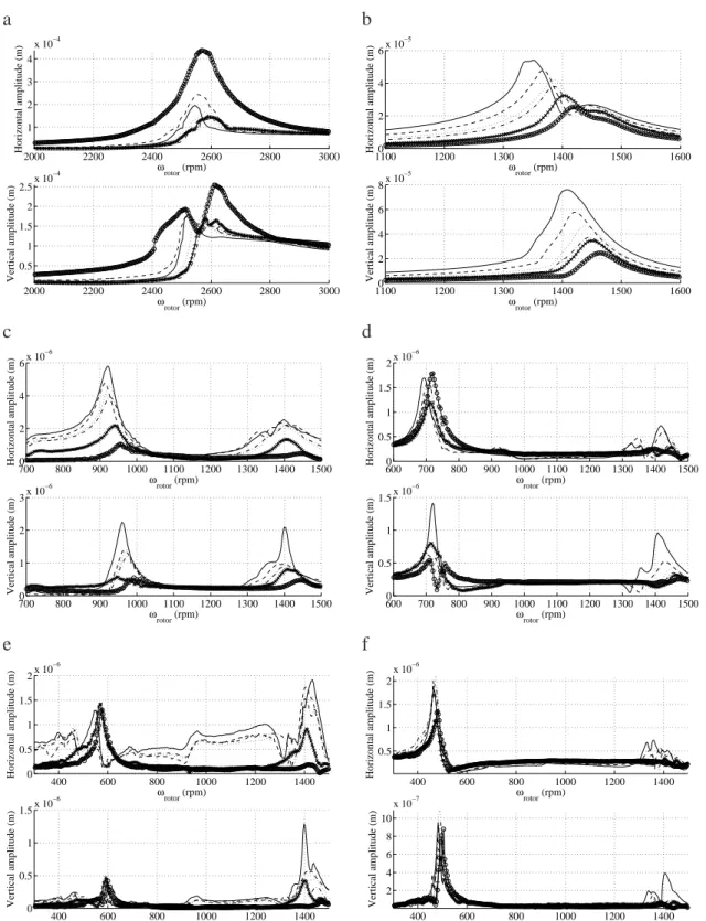
All these results can be key indicators for the detection of open cracks in a rotating shaft. All the previous results and comparisons between the healthy and slotted rotors are made when one-half of the shaft diameter is cracked. In real machine, it is interesting to detect small cracks when the crack depth is not greater than 10%-30% of the shaft diameter. So, to clarify the effects when the open crack is not very deep, experimental tests are done for various non-dimensional crack depths. Figures 8 show the evolutions of 1×, 2×, 3×, 4×, 5× and 6× amplitudes for both the vertical and horizontal directions.
First of all, the 1× amplitudes increase or decrease with the increase of the transverse slot
depth in both directions whereas the critical speed of the rotor system always decreases, as illustrated in Figure 8(a). The effect of slots on the critical speed of slotted rotors is consistent with the results reported by Sekhar and Srinivas [22], Pennacchi et al. [12], and Darpe et al. [13] From the analysis of the2× and 3× amplitudes in Figures 8(b) and (c), it is observed that the horizontal and vertical maximum amplitudes of the 2× and 3× orders growth gradually with the non-dimensional open crack depth at the 12 and
1
3 sub-critical resonant speeds, respectively.
3× maximum amplitudes are observed (at one-half and one-third of the first critical speed
re-spectively). These experimental results reflect the fact that the natural frequencies of the rotor system are changed due to the reduced stiffness resulting from the transverse slot. If the open crack is not very deep (i.e. the slot is equal toµ = 0.4), the 2× amplitudes in the horizontal di-rection are twice more important than in the case of the healthy rotor as indicated in Figure 8(b). Moreover, the vertical and horizontal peaks at one-half of the rotating speed are very important and exceed40µm. Showing the evolutions of the 3× amplitudes in the horizontal direction (see Figure 8(c)), the3× amplitudes appear to be four times more important than in the case of the healthy rotor. So the evolutions of the 2× and 3× amplitudes can be used for the detection of
an open crack even if the crack is not deep. However, it can be observed that it can be difficult to detect a transverse slot that is inferior toµ = 0.4 in the present study.
In regards to the 3× amplitudes in Figures 8(c), it is observed that the 3× amplitudes
in-crease at 12 sub-critical resonant speed with increasing the slot depth. As previously shown, the evolution of the3× amplitudes at 12 sub-critical resonant speed is significant even if the
trans-verse slot depth is not deep and is clearly recognisable if the slot depth is superior toµ = 0.4
(see the horizontal direction in Figure 8(c)). However, it may be noted that the amplitudes of
the3× amplitudes are small (about 4µm). Consequently, the detection of variations in the 2×
and3× amplitudes at one-half and one-third of the first critical speeds can be used as a
diag-nostic tool for the detection of slotted rotor if the open crack is superiorµ = 0.4. We recall that
the conclusions presented in this study are consistent with our test rig and limited to the case of an open crack. All the results that are presented in the study only give general tendencies for the vibration characteristics of slotted rotors. For a real machine, some researchers have demonstrated that it is possible to detect smaller cracks (14% of the diameter for the study of Pennacchi et al. [12] for example).
Finally, evolutions of the 4×, 5× and 6× harmonic components are given in Figures 8(d-f). In these cases, the increases of the 4×, 5× and 6× maximum amplitudes at 14,
1 5 and
1 6
sub-critical resonant speeds are not observed or not significant enough to be used as diagnostic tools. However, it is observed that increasing the crack depth increase the4× and 5× amplitudes in both the vertical and horizontal directions when the cracked rotor is passing through one-half of the first critical speed. Nevertheless, theses variations are not important enough (about 1-2
µm) and can not be used to detect the presence of a transverse crack in rotors.
3.2.2 Influence of the slot–unbalance interaction
The main objective of the following experiments is to investigate the effects of slot-unbalance interaction on the 2× and 1× response amplitudes by considering variations of the unbalance
orientation angle and, the amount of unbalance and the transverse slot depth.
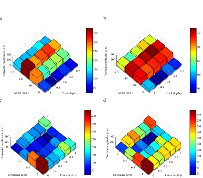
Firstly, the effects of the slot depth and the relative angle between the slot and the unbalance for the 1× maximum amplitudes when the rotor is passing through the first critical speed are shown in Figures 9(a-b) (with an unbalance of 0.4gm). Experimental results are given for
various non-dimensional slot depths in both the vertical and horizontal directions. One maxima is seen near 180◦ and one minima is at approximately0◦ for both the vertical and horizontal
and the unbalance (for0.4gm) is more important that the effects of the slot depth (for this present
study) in regards to the 1× maximum amplitudes at the first critical speed. All these results are in agreement with the level of residual unbalance that has been estimated for the healthy rotor (0.18gm at 168deg). By comparing with the experimental results previously published
by Darpe [13], it is noted that the variation of the peak response with phase of unbalance does not match exactly but looks similar to his case with a lower unbalance of0.53gm and a slotted
crack ofµ = 0.23.
Then, the effects of the amount of unbalance and the transverse slot depth are given in Fig-ures 9(c-d) by keeping a phase between the unbalance and the slot front of 0deg. It clearly
appears that the amount of unbalance drastically affect the evolutions of the1× maximum am-plitudes. For the healthy rotor, increasing the amount of unbalance increases the1× maximum amplitudes at the first critical speed for both the vertical and horizontal directions. This result is in agreement with the level of residual unbalance of the healthy rotor (0.18gm at 168deg). From
the analysis of the evolutions of the1× maximum amplitudes for the slotted rotor in Figures 9(c) and (d), the unbalance of 0.4gm now gives lower responses for all the slot depths
com-pared to the healthy rotor. The smallest horizontal and vertical amplitudes (about 40-50µm) are
observed for the transverse slot depth ofµ = 0.8. These results imply that the presence of the
slot in the rotor system modifies lightly the level of residual unbalance.
Secondly, the effects of the relative angle between the transverse slot and the unbalance for
the2× maximum amplitudes when the rotor is passing through one-half of the first critical speed
respectively, are shown in Figures 10(a-b) for various non-dimensional crack depths (with an unbalance of0.4gm at 0deg.) in both the vertical and horizontal directions. Then, the effects of
the crack depth and the amount of unbalance is given in Figures 10(c-d) (in this case the phase between the unbalance and the crack front is chosen to be0deg).
It is observed that for a given slot depth, the 2× peak amplitudes at 12 sub-critical resonant speed do not depend upon the angle between the unbalance and the slot front. Increase of the slot depth induces an increase of the2× amplitudes for all the slot–unbalance configurations.
These results are in perfect agreement with the previous study of Mayes and Davis [15]: they observed that the2× harmonic component increases monotonically with the slot depth and that there is no variation in the 2× amplitude with out-of-balance distribution. However, it can be
remembered that some numerical studies [7, 19] demonstrated that the orientation between the unbalance and the crack can affect the amplitudes of the2× peak amplitudes at 12 sub-critical
resonant speed. For example, Jun et al. [19] observed an increase of the amplitude of the second harmonic components with increasing the crack depth, but they indicated that the2× harmonic components tend to have maximum or minimum amplitudes when the unbalance is in phase and out of phase with respect to the crack. As explained by Sinou [7], the intensity of unbalance is one of the key factor that can induce changes (or not) of the2× harmonic component with the orientation between the crack and unbalance.
Considering these experimental results, it can be concluded that the changes in the 2×
am-plitudes of the rotor system through one-half of the first critical speed drastically depend on the crack depth and so appear to be the classical and robust signature for detecting the presence of an open crack in rotors.
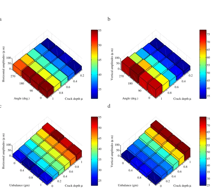
horizontal amplitudes with regard to the transverse slot depth and phase between the crack and the unbalance, and the slot depth and the unbalance intensity respectively. These results demonstrate that the differences between the 2× vertical and horizontal amplitudes increase
monotonically with the increase of the slot depth, when the rotor is passing at one-half of the first critical speed. This phenomenon is due to the increased asymmetry as slot depth increases. These results also indicate that the effects of the slot depth are stronger that those of the unbal-ance intensity or those of the phase between the slot front and the unbalunbal-ance.
So, for a rotor with an opened crack (with a given unbalance and phase with the crack front), not only changes in the 2× amplitudes in both the vertical and horizontal directions may be
used for the detection of cracks in rotors, but also differences between the 2× horizontal and vertical amplitudes can be considered as one of the most practical indicators of the presence of a crack in rotors for health-monitoring purposes.
3.2.3 Orbital evolutions
Now, the attention is focused on the evolution of the orbits around one-half and one-third of the first critical speed. Firstly, the case of a rotor with a transverse slot of relative depth of µ = 1
is investigated. As illustrated in Figures 12, the orbit of the slotted rotor at the middle of the shaft (plane A2) firstly changes from double loops to an outside loop (like a ”‘eight”’) as the speed of the rotor increases. Then, when the rotating speed of the slotted rotor reaches through half of the first critical speed, the orbit plot changes from the outside loop to a loop containing an important loop inside with a rotation of this loop indicating a significant change in both the phase and amplitude of the 2× vibration. As mentioned by Darpe et al. [13], the inner loop changes its orientation by almost180◦.
In regards to the the phase evolution of the vertical and horizontal 2× amplitudes of the slotted rotor (see Figure 3(d)), the rotor vibrates in a forward precession below1340rpm and
above1390rpm. So the horizontal phase leads the vertical phase and the double inside loop is
present. Between1340rpm and 1390rpm, this is a reverse precession orbit and the horizontal
phase lags the vertical phase as illustrated in Figure 3(d): the double outside loop appears, as shown in Figures 12. Typically, the internal loop in the direct orbit is one of the characteristic for signals containing two vibration components with the same direction of precession (see the phases of the1× and 2× components in Figures 3(b) and (d)).
By comparing the evolutions of the healthy and slotted rotors’ orbits (see Figures 5 and 12), it clearly appears that the presence of an open crack generates a strong evolution of the vibration characteristics of the rotor when the rotating speed passes through nearly half of the machine critical speed. Not only the maximum amplitudes of the orbits are modified, but also the size of the inner loop. In regards to the orbits of slotted rotor in Figures 12, it is shown that the speed range where the inside loop is present is larger than that of the healthy rotor (given in Figures 5). So the intensity of the inside loop can be used for the detection of an open crack in rotor.
To verify if the previous observations (variation and change of orbits around one-half of the first critical speed) are valid for deeper slot, experimental investigations with various slot depths are performed. Results are shown in Figures 13. First of all, the distortion in the two outside loops (i.e. the ”‘eight”’) increases when the slot depth increases, as indicated in Figures 13 (for
the rotating speedωrotor = 1340rpm). For planes A1 and A2, even if the slot depth is small
(see for example the case ofµ = 0.4), the orbital patterns are different from the healthy rotor.
Therefore, the detection of an open crack can be done by using the evolutions of the outside loops before crossing 12 sub-critical resonance. However, the differences of the two outside loops for the different slot depths (fromµ = 0.4 to µ = 1) are not significant enough significant
enough to be estimate the size of the slot.
Then, when the orbit changes from a double loop to an inside loop (i.e just before crossing
1
2 sub-critical resonance), the inside loop increases with increasing the transverse slot depth for
the three positions of the shaft at the left, middle and right of the rotor, as illustrated in Figures 13(d), (e) and (f) respectively (for the rotating speed ωrotor = 1410rpm). After crossing
1 2
sub-critical resonance (at ωrotor = 1530rpm), Figures 13(g), (h) and (i) show that the same
results are observed: increasing the slot increases monotonically the inside loop for the three planes A1, A2 and A3. This results are in perfect agreement with the numerical study of Jun et al. [19]. In regards to the orbital patterns at ωrotor = 1410rpm (see Figures 13(d), (e) and
(f)), it can be concluded that the vibration characteristics of the slotted rotor are different from those of the healthy rotor even if the slot depth is not deep. Moreover, the size of the inside loop is a good indicator of the slot depth. From the analysis of the evolutions of the orbital patterns from ωrotor = 1410rpm to ωrotor = 1530rpm, it is observed that the rotation of the
inside loop indicating a significant change in both the phase and amplitude of the2× vibration is recognisable and significant enough to be the signature of the presence of a transverse slot in rotor. For example, Figures 13(d) and (g) indicate that the inner loop changes its orientation by almost180◦.
Showing Figures 13(d), (e) and (f), the difference between the horizontal and vertical sizes of the inside loops increase with the increase of the slot depth. These results agree with the previous observations done in Section 3.2.2 for the evolutions and differences of the2× ampli-tudes in the vertical and horizontal ampliampli-tudes. So it clearly appears that the orbital changes of the inside loop can be one of the most efficient and robust signature for detecting the presence of a transverse crack in rotors.
In conclusion, all these results clearly indicate the change in both the phase and the ampli-tude of the2× harmonic components around one-half of the first critical speed, as previously
explained in Section 3.2.1. The size of the inside loop is drastically affected by the slot depth even if the open crack is not very deep. So, the orbital movements of the rotor through the passage of one-half of the first critical speed can be used as the signature of a transverse slot in the rotor.
Now, the effects of the unbalance, and the relative orientation angle between the transverse slot and the unbalance near the rotational speeds at 12 of the first critical speed are investigated.
Figures 14(a) and (b) illustrate the orbital changes at the middle of the rotor (plane A2).
From the analysis of the orbits in Figure 14(a), it appears that the orbital evolutions with increasing the unbalance are not significant for a given slot depth (i.e. µ = 1). The sizes
of the inside and outside loops are practically the same for all the cases. Then, Figure 14(b) indicates that the outside and inside loops are not also drastically affected by the variation of the angle between the slot front and the unbalance. These observations can be correlated with the evolutions of the2× amplitudes of the rotor system through one-half the first critical speed,
as previously explained in Section 3.2.2.
In conclusion, the distortion of the orbit and changes of the size for the inside loop in the orbit at one-half of the first critical speed can be consider as a robust damage assessment technique for the non-destructive detection of a transverse slot.
4
Conclusion
This study presents an experimental work on the vibration characteristics of a slotted rotor that corresponds to the case of an open crack. The presence of a transverse slot in rotor induces an increase of the contributions of then× harmonic components, and a decrease of the first critical speed and the associate n1 sub-harmonic resonances.
It is also illustrated that the diagnosis of the presence of a slot can be based only on the evolution of the2× harmonics response at one-half of the critical speeds. However, a reference case that is generally chosen to be the healthy rotor is needed in order to avoid a worse diagnostic since there are several other mechanisms in rotor that generate2× amplitudes. The response of slotted rotor can be compared with those of an asymmetric rotor.
Then, a slight increase of the inside loop of orbital patterns when the rotor speed is around one-half of the first critical speed can be a key indicator for the detection of transverse slot in a rotating shaft. Moreover, the difference between the horizontal and vertical2× amplitudes at one-half of the first critical speed appears to be a robust indicator of the presence of a slot in rotors.
So, the author hopes that the published experimental data may be useful for the future investi-gations of researchers that are currently working on the detection and identification of transverse open cracks in rotors. We recall that the results presented in this study can give general tenden-cies for the vibration characteristics of open crack rotors, but they are consistent with our test rig and limited to the case of an open crack.
Acknowledgements
The author would like to thank the financial support of the Centre National de la Recherche Sci-entifique and the laboratory LTDS UMR-CNRS 5513 (Laboratoire de Tribologie et Dynamique des Syst`emes, Unit´e Mixte de Recherche du Centre National de la Recherche Scientifique 5513) to carry out this research.
References
[1] Wauer, J., 1990. “Dynamics of cracked rotors: Literature survey”. Applied Mechanics
Review, 43, pp. 13–17 .
[2] Dimarogonas, A., 1996. “Vibration of cracked structures: a state of the art review”.
[3] Sabnavis, G., Kirk, R. G., Kasarda, M., and Quinn, D., 2004. “Cracked shaft detection and diagnostics: A literature review”. The Shock and Vibration Digest, 36(4), pp. 287–296. [4] Darpe, A., Gupta, K., and Chawla, A., 2006. “Dynamics of a bowed rotor with a transverse
surface crack”. Journal of Sound and Vibration, 296, p. 888–907.
[5] Sinou, J.-J., and Lees, A. W., 2005. “Influence of cracks in rotating shafts”. Journal of
Sound and Vibration, 285(4-5), pp. 1015–1037.
[6] Sinou, J.-J., and Lees, A. W., 2007. “A non-linear study of a cracked rotor”. European
Journal of Mechanics A/Solids, 26(1), pp. 152–170.
[7] Sinou, J.-J., 2008. “Detection of cracks in rotor based on the 2x and 3x super-harmonic frequency components and the crack-unbalance interactions”. Communication in
Non-linear Sciences and Numerical Simulation, 13, p. 2024–2040.
[8] Seibold, S., and Weiner, K., 1996. “A time domain method for the localization of cracks in rotors”. Journal of Sound and Vibration, 195(1), pp. 57–73.
[9] Darpe, K., Gupta, K., and Chawla, A., 2003. “Experimental investigations of the response of a cracked rotor to periodic axial excitation”. Journal of Sound and Vibration, 260(2), pp. 265–286.
[10] Bachschmid, N., Pennacchi, P., Tanzi, E., and Vania, A., 2000. “Identification of trans-verse crack position and depth in rotor systems”. Meccanica, 35, p. 563–582.
[11] Bachschmid, N., Pennacchi, P., and Vania, A., 2002. “Identification of multiple faults in rotor systems,”. Journal of Sound and Vibration, 254(2), pp. 327–366.
[12] Pennacchi, P., Bachschmid, N., and Vania, A., 2006. “A model-based identification method of transverse cracks in rotating shafts suitable for industrial machines”.
Mechani-cal Systems and Signal Processing, 20, p. 2112–2147.
[13] Darpe, A., Gupta, K., and Chawla, A., 2004. “Transient response and breathing behaviour of a cracked jeffcott rotor”. Journal of Sound and Vibration, 272, p. 207–243.
[14] Adewusi, S., and Al-Bedoor, B., 2002. “Experimental study on the vibration of an over-hung rotor with a propagating transverse crack”. Shock and Vibration, 9, p. 91–104. [15] Davies, W. G. R., and Mayes, I. W., 1984. “The vibrational behaviour of a multi-shaft,
multi-bearing system in the presence of a propagating transverse crack”. Transactions of
the ASME Journal of Vibration, Acoustics, Stress, and Reliability in Design, 106, pp. 146–
153.
[16] Mayes, I. W., and Davies, W. G. R., 1984. “Analysis of the response of a multi-rotor-bearing system containing a transverse crack in a rotor”. Transactions of the ASME
[17] Taylor, H., 1940. “Critical speed behaviour of unsymmetrical shafts”. Journal of Applied
Mechanics.
[18] Henry, T., and Okah, B., 1976. “Vibration in cracked shafts”. IMechE Conference on
Vibrations in Rotating Machinery, C/162/76, p. 15–19.
[19] Jun, O., Eun, H., Earmme, Y., and Lee, C., 1992. “Modelling and vibration analysis of a simple rotor with a breathing crack”. Journal of Sound and Vibration, 155(2), pp. 273– 290.
[20] Plaut, R., Andruet, R., and Suherman, S., 1994. “Behaviour of a cracked rotating shaft during passage through a critical speed”. Journal of Sound and Vibration, 173, pp. 577– 589.
[21] Bachschmid, N., Pennacchi, P., Tanzi, E., and Audebert, S., 2003. “Transverse crack mod-eling and validation in rotor systems, including thermal effects”. International Journal of
Rotating Machinery, 9(2), pp. 113–126.
[22] Sekhar, A. . S., and Srinivas, B. N., 2002. “Vibration characteristics of slotted shafts”.
a b 5000 1000 1500 2000 2500 3000 3500 4000 2 4 6 8x 10 −5 ωrotor (rpm) Amplitude (m) 500 1000 1500 2000 2500 3000 3500 4000 −200 −100 0 100 200 ωrotor (rpm) Phase (deg.) 5000 1000 1500 2000 2500 3000 3500 4000 1 2 3x 10 −4 Amplitude (m) ωrotor (rpm) 500 1000 1500 2000 2500 3000 3500 4000 −200 −100 0 100 200 Phase (deg.) ωrotor (rpm) c d 5000 1000 1500 2000 2500 3000 3500 4000 1 2 3x 10 −5 ωrotor (rpm) Amplitude (m) 500 1000 1500 2000 2500 3000 3500 4000 −200 −100 0 100 200 ωrotor (rpm) Phase (deg.) 500 1000 1500 2000 2500 3000 3500 4000 0 2 4 6 8x 10 −5 ωrotor (rpm) Amplitude (m) 500 1000 1500 2000 2500 3000 3500 4000 −200 −100 0 100 200 ωrotor (rpm) Phase (deg.) e f 5000 1000 1500 2000 2500 3000 3500 4000 1 2 3x 10 −6 ω rotor (rpm) Amplitude (m) 500 1000 1500 2000 2500 3000 3500 4000 −200 −100 0 100 200 ωrotor (rpm) Phase (deg.) 500 1000 1500 2000 2500 3000 3500 4000 0 2 4 6 8x 10 −6 ω rotor (rpm) Amplitude (m) 500 1000 1500 2000 2500 3000 3500 4000 −200 −100 0 100 200 ω rotor (rpm) Phase (deg.)
Figure 2: Evolution of n× amplitudes and phase in plane A2 for the healthy and slotted ro-tors (µ = 1) with the initial residual unbalance (a) 1×, healthy rotor (b) 1×, slotted rotor (c)
a b 5000 1000 1500 2000 2500 3000 3500 4000 2 4 6x 10 −4 ωrotor (rpm) Amplitude (m) 500 1000 1500 2000 2500 3000 3500 4000 −200 −100 0 100 200 ωrotor (rpm) Phase (deg.) 5000 1000 1500 2000 2500 3000 3500 4000 0.5 1 1.5 2x 10 −4 ωrotor (rpm) Amplitude (m) 500 1000 1500 2000 2500 3000 3500 4000 −200 −100 0 100 200 ωrotor (rpm) Phase (deg.) c d 5000 1000 1500 2000 2500 3000 3500 4000 1 2 3x 10 −5 ωrotor (rpm) Amplitude (m) 500 1000 1500 2000 2500 3000 3500 4000 −200 −100 0 100 200 ωrotor (rpm) Phase (deg.) 5000 1000 1500 2000 2500 3000 3500 4000 2 4 6 8x 10 −5 ωrotor (rpm) Amplitude (m) 500 1000 1500 2000 2500 3000 3500 4000 −200 −100 0 100 200 ωrotor (rpm) Phase (deg.) e f 5000 1000 1500 2000 2500 3000 3500 4000 1 2 3x 10 −5 ω rotor (rpm) Amplitude (m) 500 1000 1500 2000 2500 3000 3500 4000 −200 −100 0 100 200 ω rotor (rpm) Phase (deg.) 5000 1000 1500 2000 2500 3000 3500 4000 2 4 6 8x 10 −6 ω rotor (rpm) Amplitude (m) 500 1000 1500 2000 2500 3000 3500 4000 −200 −100 0 100 200 ω rotor (rpm) Phase (deg.)
Figure 3: Evolution ofn× amplitudes and phase in plane A2 for the healthy and slotted rotors
a b 500 1000 1500 2000 2500 3000 3500 4000 10−8 10−7 10−6 10−5 10−4 10−3 ωrotor (rpm) Horizontal amplitude (m) 500 1000 1500 2000 2500 3000 3500 4000 10−8 10−7 10−6 10−5 10−4 10−3 ωrotor (rpm) Vertical amplitude (m) c d 500 1000 1500 2000 2500 3000 3500 4000 10−7 10−6 10−5 10−4 ωrotor (rpm) Horizontal amplitude (m) 500 1000 1500 2000 2500 3000 3500 4000 10−8 10−7 10−6 10−5 10−4 ωrotor (rpm) Vertical amplitude (m)
Figure 4: Evolution of the global response, 1×, 2× and 3× amplitudes for the healthy and slooted rotors (µ = 1) with an unbalance of 1gm and a phase between the unbalance and the
crack front of 0 degree. (a-b) plane A1 (c-d) plane A3 (solid lines = uncracked rotor, dashed lines = cracked rotor, black = global amplitudes, blue =1×, green= 2×, red = 3×)
2e−005 4e−005 5e−005 0.0001 5e−005 0.0001 5e−005 0.0001
ωrotor = 1285rpm ωrotor = 1345rpm ωrotor = 1385rpm ωrotor= 1405rpm
5e−005 0.0001 2.5e−005 5e−005 2.5e−005 5e−005 2e−005 4e−005
ωrotor = 1425rpm ωrotor = 1445rpm ωrotor = 1470rpm ωrotor= 1590rpm
Figure 5: Orbital evolutions for the healthy rotor for the plane A2 around one-half of the first critical speed with an unbalance of 1gm and a phase between the unbalance and the crack front of 0 deg.
500 1000 1500 2000 2500 3000 3500 4000 1 2 3 4 5 6 ω rotor (rpm) Order 0.1 0.2 0.3 0.4 0.5 0.6 0.7 0.8 0.9
Figure 6: Evolutions of the nth
orders for the healthy rotor with an unbalance of 1gm and a phase between the unbalance and the crack front of 0 deg.
500 1000 1500 2000 2500 3000 3500 4000 1 2 3 4 5 6 ωrotor (rpm) Order 0.1 0.2 0.3 0.4 0.5 0.6 0.7 0.8 0.9
Figure 7: Evolutions of thenth
orders for the slotted rotor withµ = 1 (unbalance = 1gm, phase
a b 2000 2200 2400 2600 2800 3000 1 2 3 4 x 10⁻⁴ ωrotor (rpm) Horizontal amplitude (m) 2000 2200 2400 2600 2800 3000 0.5 1 1.5 2 2.5x 10 −4 ωrotor (rpm) Vertical amplitude (m) 11000 1200 1300 1400 1500 1600 2 4 6x 10 −5 ωrotor (rpm) Horizontal amplitude (m) 11000 1200 1300 1400 1500 1600 2 4 6 8x 10 −5 ωrotor (rpm) Vertical amplitude (m) c d 700 800 900 1000 1100 1200 1300 1400 1500 0 2 4 6x 10 −6 ωrotor (rpm) Horizontal amplitude (m) 700 800 900 1000 1100 1200 1300 1400 1500 0 1 2 3x 10 −6 ωrotor (rpm) Vertical amplitude (m) 600 700 800 900 1000 1100 1200 1300 1400 1500 0 0.5 1 1.5 2x 10 −6 ωrotor (rpm) Horizontal amplitude (m) 600 700 800 900 1000 1100 1200 1300 1400 1500 0 0.5 1 1.5x 10 −6 ωrotor (rpm) Vertical amplitude (m) e f 400 600 800 1000 1200 1400 0 0.5 1 1.5 2x 10 −6 ω rotor (rpm) Horizontal amplitude (m) 400 600 800 1000 1200 1400 0 0.5 1 1.5x 10 −6 ω rotor (rpm) Vertical amplitude (m) 400 600 800 1000 1200 1400 0.5 1 1.5 2 x 10⁻⁶ ω rotor (rpm) Horizontal amplitude (m) 400 600 800 1000 1200 1400 2 4 6 8 10 x 10−7 ω rotor (rpm) Vertical amplitude (m)
Figure 8: Evolutions of then× amplitudes for various crack depths with an unbalance of 1gm and a phase between the unbalance and the slot front of 0 deg. (a)1× - plane A2, (b) 2× - plane A2, (c)3× - plane A1, (d) 4× - plane A3, (e) 5× - plane A1, (f) 6× - plane A3 (-o- uncracked,
a b 1 0.8 0.6 0.4 0.2 0 90 180 270 0 200 400
Angle (deg.) Crack depth µ
Horizontal amplitudes ( µ m) 50 100 150 200 250 300 350 1 0.8 0.6 0.4 0.2 0 90 180 270 0 200 400
Angle (deg.) Crack depth µ
Vertical amplitudes ( µ m) 50 100 150 200 250 c d 0 0.2 0.4 0.6 0.8 1 1 0.8 0.4 0 0 250 500
Unbalance (gm) Crack depth µ
Horizontal amplitudes ( µ m) 50 100 150 200 250 300 350 400 0 0.2 0.4 0.6 0.8 1 1 0.8 0.4 0 0 200 400
Unbalance (gm) Crack depth µ
Vertical amplitudes ( µ m) 40 60 80 100 120 140 160 180 200 220 240
Figure 9: Evolutions of the1× maximum amplitudes at the first critical speed for the horizontal
and vertical directions at the plane 2 (a,b) versus the slot depth and the phase between the unbalance and the slot front for an unbalance of 0.4gm (c,d) versus the slot depth and the unbalance with a phase between the unbalance and the slot front of 0 deg.
a b 1 0.8 0.6 0.4 0.2 0 90 180 270 0 50 100 Horizontal amplitudes ( µ m) Crack depth µ Angle (deg.) 35 40 45 50 55 1 0.8 0.6 0.4 0.2 0 90 180 270 0 50 100
Angle (deg.) Crack depth µ
Vertical amplitudes ( µ m) 35 40 45 50 55 60 65 70 75 c d 0 0.2 0.4 0.6 0.8 1 1 0.8 0.4 0 0 50 100
Unbalance (gm) Crack depth µ
Horizontal amplitudes ( µ m) 25 30 35 40 45 50 55 0 0.2 0.4 0.6 0.8 1 1 0.8 0.4 0 0 50 100
Unbalance (gm) Crack depth µ
Vertical amplitudes ( µ m) 25 30 35 40 45 50 55 60 65 70 75
Figure 10: Evolutions of the2× maximum amplitudes at one-half of the first critical speed for
the horizontal and vertical directions at the plane 2 (a,b) versus the slot depth and the phase between the unbalance and the slot front for an unbalance of 0.4gm (c,d) versus the slot depth and the unbalance with a phase between the unbalance and the slot front of 0 deg.
a b 0 0.5 1 0.2 0.4 0.6 0.8 1 0 10 20 30 Unbalance (gm) Crack depth Amplitude differences ( µ m) 0.2 0.4 0.6 0.8 1 0 90 180 270 0 10 20 30 Crack depth Phase (deg.) Amplitude differences ( µ m)
Figure 11: Differences between the horizontal and vertical directions of the2× maximum
am-plitudes at one-half of the first critical speed on plane A2 (a) for various crack depths and unbalance with a phase of 0 deg. (b) for various crack depths and phases between the unbalance and the crack front with an unbalance of 0.4gm
5e−005 0.0001 5e−005 0.0001 5e−005 0.0001 0.00015 5e−005 0.0001 0.00015
ωrotor= 1280rpm ωrotor = 1310rpm ωrotor = 1350rpm ωrotor = 1370rpm
5e−005 0.0001 0.00015 5e−005 0.0001 0.00015 5e−005 0.0001 0.00015 5e−005 0.0001 0.00015
ωrotor= 1380rpm ωrotor = 1400rpm ωrotor = 1420rpm ωrotor = 1440rpm
5e−005 0.0001 5e−005 0.0001 2.5e−005 5e−005 2e−005 4e−005
ωrotor= 1450rpm ωrotor = 1470rpm ωrotor = 1530rpm ωrotor = 1585rpm
Figure 12: Orbital evolutions of the cracked rotor for plane A2(withµ = 1) around one-half
of the first critical speed with an unbalance of 1gm and a phase between the unbalance and the crack front of 0 deg.
a b c 5e−005 0.0001 5e−005 0.0001 0.00015 2.5e−005 5e−005 d e f 5e−005 0.0001 5e−005 0.0001 0.00015 1e−005 2e−005 3e−005 g h i 5e−005 0.0001 5e−005 0.0001 1e−005 2e−005 3e−005
Figure 13: Orbits of the cracked rotor around one-half of the first critical speed with an unbal-ance of 1gm and a phase between the unbalunbal-ance and the crack front of 0 deg. (red: µ = 1,
magenta:µ = 0.8, blue: µ = 0.6, black: µ = 0.4). (a) Plane A1 - ωrotor= 1340rpm, (b) Plane
A2 -ωrotor = 1340rpm, (c) Plane A3 - ωrotor = 1340rpm, (d) Plane A1 - ωrotor = 1410rpm,
(e) Plane A2 - ωrotor = 1410rpm, (f) Plane A3 - ωrotor = 1410rpm, (g) Plane A1
a b 5e−005 0.0001 0.00015 5e−005 0.0001 0.00015
Figure 14: Changes in the orbital patterns at the one-half of the first critical speed as a function of (a) the phase withµ = 1 and an unbalance of 1gm ( red: 0 deg., magenta: 90 deg., blue: 180
deg., black: 270 deg.), (b) the unbalance withµ = 1 and a phase of 0 deg. (black: 0gm, blue: 0.4gm, magenta: 0.8gm, red: 1gm)