HAL Id: hal-02417789
https://hal.archives-ouvertes.fr/hal-02417789
Submitted on 18 Dec 2019
HAL is a multi-disciplinary open access
archive for the deposit and dissemination of
sci-entific research documents, whether they are
pub-lished or not. The documents may come from
teaching and research institutions in France or
abroad, or from public or private research centers.
L’archive ouverte pluridisciplinaire HAL, est
destinée au dépôt et à la diffusion de documents
scientifiques de niveau recherche, publiés ou non,
émanant des établissements d’enseignement et de
recherche français ou étrangers, des laboratoires
publics ou privés.
L. Berge, N. Estre, D. Tisseur, E. Payan, D. Eck, V. Bouyer, N.
Cassiaut-Louis, C. Journeau, R. Letellier, E. Pluyette
To cite this version:
L. Berge, N. Estre, D. Tisseur, E. Payan, D. Eck, et al.. Fast high-energy X-ray imaging for Severe
Accidents experiments on the future PLINIUS-2 platform. ANIMMA-2017, Jun 2017, Liege, Belgium.
�hal-02417789�
Abstract— The future PLINIUS-2 platform of CEA Cadarache
will be dedicated to the study of corium interactions in severe nuclear accidents, and will host innovative large-scale experiments. The Nuclear Measurement Laboratory of CEA Cadarache is in charge of real-time high-energy X-ray imaging set-ups, for the study of the corium-water and corium-sodium interaction, and of the corium stratification process. Imaging such large and high-density objects requires a 15 MeV linear electron accelerator coupled to a tungsten target creating a high-energy Bremsstrahlung X-ray flux, with corresponding dose rate about 100 Gy/min at 1 m. The signal is detected by phosphor screens coupled to high-framerate scientific CMOS cameras. The imaging set-up is established using an experimentally-validated home-made simulation software (MODHERATO). The code computes quantitative radiographic signals from the description of the source, object geometry and composition, detector, and geometrical configuration (magnification factor, etc.). It accounts for several noise sources (photonic and electronic noises, swank and readout noise), and for image blur due to the source spot-size and to the detector unsharpness. In a view to PLINIUS-2, the simulation has been improved to account for the scattered flux, which is expected to be significant. The paper presents the scattered flux calculation using the MCNP transport code, and its integration into the MODHERATO simulation. Then the validation of the improved simulation is presented, through confrontation to real measurement images taken on a small-scale equivalent set-up on the PLINIUS platform. Excellent agreement is achieved. This improved simulation is therefore being used to design the PLINIUS-2 imaging set-ups (source, detectors, cameras, etc.).
Index Terms— X-ray imaging, MODHERATO, PLINIUS-2,
Severe Accidents, Corium
I. INTRODUCTION
HE study of severe nuclear accidents is a major research topic at CEA (French atomic energy agency). In this scope, the PLINIUS experimental platform situated in
All authors work at CEA, DEN, Cadarache, F-13108 Saint-Paul-lez-Durance, France.
L. Berge, N. Estre, D. Tisseur, E. Payan and D. Eck are with Nuclear Measurement Laboratory (LMN).
V. Bouyer, N. Cassiaut-Louis, C. Journeau, R. Le Tellier are with Severe Accidents Physics and Modeling Laboratory (LPMA).
E. Pluyette is with Instrumentation and Technological Assays Laboratory (LIET).
Cadarache studies the behavior of corium (melt fuel-structure mixture), through several experimental set-ups [1]. The tests performed on this facility provide crucial data and validation for the models elaborated at CEA. Among the test facilities of PLINIUS, the KROTOS facility studies the corium-water interaction, through the release of corium into a water tank [2]. It includes high-frequency X-ray imaging through the whole process, which allows a worldwide unique real-time visualization of the reaction [3] (see Fig. 1).
Fig. 1. High-energy X-ray visualization of the corium-water interaction on the KROTOS facility [4]
Imaging the water test column requires an X-ray spectrum of the MeV order of magnitude. A 9 MeV linear electron accelerator (LINAC) coupled to a tungsten target is used to produce an X-ray pulsed cone-beam. The dose rate is about 15 Gy/min at 1 m. The detector is composed of a scintillating Gadox plate coupled to four high-framerate sCMOS cameras. The reaction kinetics (corium fragmentation) imposes a high image frequency in order to decompose the reaction process. Each camera reads up to 50 Hz, and the LINAC pulse frequency is set so that there is one image per pulse (200 Hz at most).
The Fukushima accident in 2011 has launched new effort in the field of severe accidents study. A new platform named PLINIUS-2 is planned in Cadarache, and will be dedicated to larger-scale experiments for corium study (higher corium masses) [5]. In addition to water reactors, the PLINIUS-2 field of study will cover future sodium-cooled fast reactors under design by CEA.
High-energy X-ray imaging will be required on three experiments of PLINIUS-2: the test sections for water-corium interaction and sodium-corium interaction study, and the stratification process study. Higher attenuation than in KROTOS is expected on these bigger test columns. In this scope, the design of imaging set-ups is carefully examined and
Fast high-energy X-ray imaging for Severe
Accidents experiments on the future PLINIUS-2
platform
L. Berge, N. Estre, D. Tisseur, E. Payan, D. Eck, V. Bouyer, N. Cassiaut-Louis, C. Journeau,
R. Le Tellier, and E. Pluyette
design for PLINIUS-2 is made on a simulation basis, with the KROTOS imaging performances as a target (millimetric detection limit, relative noise level about 1%). The simulation is based on the MODHERATO code, which produces simulated radiographies, quantitatively comparable to the images obtained by a real imaging system. Section II will describe the simulation principle, and validation through confrontation to real images taken on KROTOS. Then, application to the design and imaging performances previsions for the future PLINIUS-2 imaging set-ups will be discussed in section III. Section IV will finally present the conclusion and perspectives of this work.
II. UPGRADE OF THE SIMULATION AND VALIDATION
The MODHERATO code has been developed by CEA/LMN for high-energy imaging applications in radiography and tomography. In the view of the PLINIUS-2 design studies, the simulation has been improved and validated on an experimental basis, in order to allow fine quantitative prediction of the future imaging system performances. We present in this chapter the simulation principle of MODHERATO applied to point-source radiography, as well as the confrontation with experimental images on the case of KROTOS.
A. Simulation in cone-beam radiography
Computation of the radiographic signal includes two distinct steps. The first step is the exponential attenuation of the X-ray beam through the matter up to the detector. This step requires:
Description of the angular and energetic distributions of the X-ray source. This requires a Monte Carlo computation using the MCNP-6 code [6], describing the electron beam and conversion target. The calculation is done once for all for a given LINAC;
Description of the geometrical objects present in the path of the X radiation to the detector, with their elementary composition and density (description of the test column, and description of corium and vapor inside the column for example);
Tabulated data for the photon-matter interaction cross-sections [7];
The distances between source, object and detector (magnification factor).
The attenuated flux I(y,z) incident on point (y,z) of the 2D detector is related to the source flux I0(y,z) emitted in direction
of point (y,z) by:
m m me
z
y
I
z
y
I
,
,
ln
0where, for each material m on the path from the source to point (y,z), m is the attenuation coefficient (in cm
-1
) and em is
the thickness crossed by the X-ray in this material.
The second part of the simulation is the computation of the detector response. In a KROTOS-like configuration (scintillator and camera coupling), this requires:
For a given scintillator material and thickness, a preliminary calculation with MCNP of the detection efficiency , and the mean energy deposited by the X-photon as a function of its energy, as well as the associated dispersion (“swank noise”);
The scintillation yield;
The de-magnification factor (phosphor screen dimensions over camera sensor dimensions);
The camera characteristics: electronic yield, readout noise, numerical conversion.
The detected X-ray flux is randomly sampled in a Poissonian law around the mean value I to account for the statistical
noise. It is then converted into visible photon flux, then into electron flux also randomly sampled in a Poissonian law around the mean value, then into numerical signal in ADC1 units. The simulated signal noise, in addition to the statistical fluctuation of X-photons and visible photons counting, accounts for the swank and readout noise sources.
The simulation also accounts for the source spot-size, and for the detector response FWHM for a point-source, resulting in image blur.
The absolute simulated signal in ADC units is quantitatively comparable to experimental raw signals taken on the corresponding configuration without any background subtraction or normalization.
B. Scattered X-ray flux contribution
The use of a 2D phosphor plate induces high contribution of the scattered X-ray flux, i.e. photons that encountered trajectory deviation due to Compton scattering inside the test column. The signal induced by these photons will be mis-interpreted as coming directly from the source.
The MCNP code is used to evaluate the bias on the X-ray flux incident on the detector. At each point of the detector, MCNP gives the proportion of X-photons that encountered at least one scattering event on their path from the source to the detector. A map of scattered X-ray flux Is(y,z) on each point of
the detector is then constituted once for all in a given configuration. Scattering due to objects inside the column is considered as high as scattering due to the background (water or sodium for PLINIUS-2). In the presence of corium, the scattering flux will then be slightly overestimated.
The MODHERATO code has been upgraded to take the scattered-photon flux map on the detector surface as an input, and add it to the attenuated direct flux I. The total flux on the detector surface corresponds to both direct and scattered flux contributions: Itot(y,z) = I(y,z) + Is(y,z). Fig. 2 shows the ratio
of direct over scattered flux on the Gadox plate in KROTOS, given by MCNP. This ratio is around 2, i.e. the scattered flux represents about 1/3 of the total flux. It is interesting to note that the direct flux I on the detector is peaked on the image center, due to the LINAC emitting preferentially forward, whereas the scattered flux is rather spread on the image. The
scattering is therefore less disadvantageous in the image center.
Fig. 2. Ratio of direct flux over scattered flux on the Gadox screen for the KROTOS water test section (MCNP simulation).
C. Validation on KROTOS images
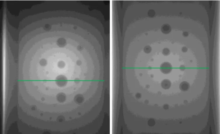
KROTOS is a good representation of the future PLINIUS-2 imaging challenges. Especially for the corium-coolant interaction (interaction of corium with water or sodium), the future experiments are extended from KROTOS. Images taken on KROTOS with a known phantom were used to validate the simulation. The phantom consists in a polyethylene cylinder of density 0.95, representing water (similar density and attenuation power), containing various steel balls of known positions and diameters (see Fig. 3). This phantom was created originally to estimate the detection limit of the set-up.
Fig. 3. Steel balls phantom: polyethylene cylinder (left). The inside of the cylinder is filled either with polyethylene or with the plate containing the balls (right).
Fig. 4 presents the real image from one of the four cameras, together with the simulated image using the same grey-scale. Fig. 5 shows the signal on the central horizontal profile (pictured in green on Fig. 4), in the case of real image (raw signal from one camera, in ADC units) and simulated image (simulation signal in ADC units). The simulated profile without scattered flux contribution is also presented to highlight the scattering correction impact.
Fig. 4. Real image (left) and corresponding simulated image (right) of the steel balls phantom on KROTOS.
Fig. 5. Comparison between real signal taken on KROTOS and corresponding simulated signal from MODHERATO, with and without scattering, for the green profile of Fig. 4.
The account of scattered flux significantly reduces discrepancy between simulated and measured data as expected. Very good agreement is achieved, especially near the image center. Near the edge of the picture, the measured signal darkens due to a vignetting effect of the camera objective, which is not simulated to date. The noise level is also well reproduced by the simulation: around 1.2% of the total signal.
As it was shown in paragraph A, the simulation only relies on parameters obtained by simulation (MCNP) or known from the cameras documentation. No empirical artefact is added to the calculated signal. Therefore, the good agreement with the measured data is a validation that the simulation is predictive for such systems.
III. DESIGN OF THE FUTURE PLINIUS-2 IMAGING SET-UPS AND ASSOCIATED PREDICTED PERFORMANCES
The PLINIUS-2 imaging set-ups will rely on the same principle as KROTOS on which the simulation was validated,
i.e. radiography using a LINAC and phosphor screens coupled
to sCMOS cameras. The imaging performances estimation on the different PLINIUS-2 experiments is therefore based on the simulation presented in paragraph II.
PLINIUS-2 will host bigger test columns for the study of corium-sodium interaction (IC-Na) and corium-water interaction (IC-E). A detailed study of the imaging performances expected on IC-Na has already been performed based on the MODHERATO simulation described in paragraph II. A similar design study will be done for IC-E imaging as well. In the following, we will summarize the results obtained for IC-Na and the main characteristics of the future IC-E imaging set-up.
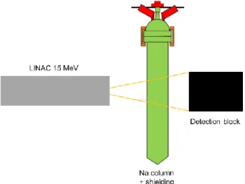
The principle for IC-Na is the same as on KROTOS (see Fig. 6): sudden hot corium release in a test column, filled with liquid sodium about 800°C instead of water.
Fig. 6. Schematic view of the PLINIUS-2 IC-Na experiment. The corium is released from the top of the column and falls into the sodium test section.
The X-ray attenuation in matter depends for a part on the nature of elements composing the material and on the X-ray energy. But for a given X-ray source, the attenuation is mostly related to the surface density, defined as the product of the material density and thickness e. The surface density of KROTOS is 36 g/cm2, whereas the IC-Na surface density will be 137 g/cm2, due to a larger sodium column and to important thermal shielding, and despite the liquid sodium density of 0.75. Therefore, the 9 MeV LINAC in use on KROTOS would not give enough output flux for a good quality image. A 15 MeV LINAC will be used, delivering about 100 Gy/min at 1 m. The optical coupling between the Gadox plate and the sCMOS cameras is also optimized. Instead of having 1 camera per acquisition and 4 cameras alternating to achieve a better image frequency, on IC-Na the 4 cameras will be required for each image. This implies a reduction in the image frequency to about 100 Hz, which is an acceptable frequency for the LINAC. The collected optical signal emitted by the Gadox layer is then 4 times higher than with only one camera. Another option is considered for the scintillating material, by replacing the Gadox 2D plate by a set of LYSO
(Lu2(1-x)Y2xSiO5:Ce) scintillating crystals jointed together on a
2D screen. These crystals have high detection efficiency for several MeV photons: about 35% for a 2 cm thick LYSO crystal, for about 4% for the current KROTOS 1.4 mm tick Gadox layer. Due to the achievable size for current LYSO
for a radiographic magnification factor of 1.45. Both options (LYSO assembly or Gadox screen) are currently considered and were evaluated by simulation. Additional MCNP calculations were run prior to the MODHERATO simulation: one to get the characteristics of the 15 MeV source (energy and angular distributions), one to get the scattered X-ray flux associated to the IC-Na configuration, and one to describe the LYSO crystals (deposited energy per X-ray energy and swank noise). Fig. 7 shows the expected signal, obtained with MODHERATO, for the same iron balls as on the phantom of Fig. 3 in the PLINIUS-2 IC-Na test section, for both scintillator options. The KROTOS signal is also shown on the same figure for comparison. With the 15 MeV LINAC and 4 cameras instead of 1, we finally get more output signal than we have on KROTOS, despite the high-attenuating sodium section. Moreover, the use of LYSO crystals instead of the Gadox screen significantly increases the signal, and thus, reduces the statistical noise level. We remind here that the noise is also simulated.
Fig. 7. Expected signal obtained on PLINIUS-2 IC-Na with the same iron balls than on the KROTOS phantom of Fig. 3 (simulation). The KROTOS signal is shown for comparison. The two scintillator options, Gadox and LYSO screens, are shown.
Fig. 8. Contrast-to-noise ratio corresponding to the signals of Fig. 7 for PLINIUS-2 IC-Na (Gadox or LYSO screen) and in the case of KROTOS.
Fig. 8 shows the contrast-to-noise ratio associated to these signals. A contrast of more than 5 times the background noise level (i.e. contrast-to-noise ratio superior to 5) is the criterion of object detectability (detection limit). The noise being for a large part related to the X-ray flux, and less dependent on the scintillator-camera coupling, the Gadox configuration leads to a lower contrast-to-noise ratio than on KROTOS where the output signal is lower. In the case of the LYSO screen on the contrary, we get higher contrast-to-noise ratio: around twice the values obtained with Gadox, which leads directly to the ability to detect twice smaller objects. The detection limit is determined using the balls phantom, as the diameter of the smallest detected ball. The phantom contains balls of various diameters, especially every 1 mm between 2 mm and 10 mm. The detection limit is about 8 mm for the Gadox solution which is the same detection limit obtained on KROTOS, and falls down to 5 mm for the LYSO crystals.
In both cases (Gadox or LYSO) the use of a 15 MeV LINAC and 4 cameras leads to a detection limit and noise level of the same order than on KROTOS. The design of IC-Na is therefore validated.
The IC-E test section geometry and composition is under design, the associated imaging set-up design will be close to the one for IC-Na. The surface density of the column should not exceed that of the IC-Na test section, around 137 g/cm2, in order to have a comparable attenuation.
B. Corium stratification experiment
Imaging will also be required for the study of corium stratification. The experiment consists in observing the evolution of different corium phases inside a crucible of diameter about 30 cm. A feasibility study for a real-time X-ray imaging with a framerate of 1 image/s has been performed using MODHERATO, accounting for scattering, based on corium behavior previsions. The corium cylinder is decomposed into 33 slices of different chemical composition and density. The time evolution of these 33 slices is discretized into 17 configurations. Fig. 9 shows images calculated with MODHERATO of 3 typical configurations using a 15 MeV LINAC, and the same detector as on KROTOS (Gadox coupled to 1 camera per image). The interfaces between different type of corium phases (oxide, light metal, heavy metal) are detectable, as shown on Fig. 10. A more detailed study is planned in a close future to establish the ability of high-energy X-ray imaging to study the shape evolution of these interfaces.
Fig. 9. Evolution of the different corium phases (simulation radiography images).
Fig. 10. Vertical profile of corium cylinder in configuration 7 (simulation), indicated in green on Fig. 9. The two peaks correspond to the two interfaces visible on Fig. 9.
IV. CONCLUSION
In this paper, we have presented real-time X-ray imaging which is a high value-added feature of severe nuclear accidents study performed at CEA in Cadarache. Such an imaging set-up is already used on the PLINIUS platform with success, and will be extended for the future PLINIUS-2 platform large-scale test facilities, on which higher attenuation is expected. These new imaging systems will require the use of a more powerful 15 MeV source, instead of the current 9 MeV LINAC.
We described the simulation principle, using the MODHERATO code developed at CEA Cadarache, from the description of the source spectrum, object geometry and detector characteristics, to obtain a simulated “raw” signal in the same units as the signal from the cameras. The simulation includes calculation of statistical noise, due to X-photons and scintillation photons, swank and readout noises, as well as image blur due to the source spot-size and detector unsharpness. The simulated signal also accounts for the scattered flux contribution, calculated beforehand using the MCNP transport code. We also presented a comparison between measured and simulated “raw” signals, in the case of a phantom used on KROTOS. Since excellent agreement is achieved, the simulation was validated. The imaging performances expected on PLINIUS-2 were then estimated using the simulation. A design study for the future IC-Na imaging set-up was performed using MODHERATO, which confirms performances of the order of the KROTOS imaging quality. A feasibility study has also been performed for high-energy X-ray imaging for corium stratification study, giving satisfactory results. A similar study is planned for the imaging design on the future IC-E test section.
REFERENCES
1. C. Journeau, “Severe accident research at the PLINIUS
prototypic platform” in ICAPP’05., Seoul., Korea, 2005, pp.
1074
2. M. Bonnet et al., “KROTOS FCI Programme at CEA
Cadarache”,. ICAPP-05, Seoul, KOREA, May 15-19, 2005,
Paper 5381
3. N. Estre et al., “Fast Megavoltage X-Rays Radioscopy”, proc. of IEEE-NSS/MIC, Strasbourg, 2016
Journal of Energy and Power Engineering 7 (2013), pp 423-431
5. Ch. Journeau et al., “Corium-sodium and corium-water
fuel-coolant-interaction experimental programs for the PLINIUS-2 prototypic corium platform”, NURETH-17, Xi’an,
China, Sept. 3-8, 2017 (to be published)
6. J. Goorley et al., “Initial MCNP6 Release Overview -
MCNP6 version 1.0”, LA-UR-13-22934 NEA report, 2013
7. M.J. Berger and J.H. Hubbell, XCOM: Photon cross-section database: https://www.nist.gov/pml/xcom-photon-cross-sections-database
![Fig. 1. High-energy X-ray visualization of the corium-water interaction on the KROTOS facility [4]](https://thumb-eu.123doks.com/thumbv2/123doknet/12695652.355225/2.918.515.805.505.614/high-energy-visualization-corium-water-interaction-krotos-facility.webp)