HAL Id: hal-00910188
https://hal.archives-ouvertes.fr/hal-00910188
Preprint submitted on 27 Nov 2013
HAL is a multi-disciplinary open access
archive for the deposit and dissemination of
sci-entific research documents, whether they are
pub-lished or not. The documents may come from
teaching and research institutions in France or
abroad, or from public or private research centers.
L’archive ouverte pluridisciplinaire HAL, est
destinée au dépôt et à la diffusion de documents
scientifiques de niveau recherche, publiés ou non,
émanant des établissements d’enseignement et de
recherche français ou étrangers, des laboratoires
publics ou privés.
Perfect and robust phase-locking of a spin transfer
vortex nano-oscillator to an external microwave source
A. Hamadeh, Nicolas Locatelli, V. V. Naletov, Romain Lebrun, G. de
Loubens, Julie Grollier, Olivier Klein, V. Cros
To cite this version:
A. Hamadeh, Nicolas Locatelli, V. V. Naletov, Romain Lebrun, G. de Loubens, et al.. Perfect and
robust phase-locking of a spin transfer vortex nano-oscillator to an external microwave source. 2013.
�hal-00910188�
linewidth is found to decrease by more than five orders of magnitude in the phase-locked regime (down to 1 Hz, limited by the resolution bandwidth of the spectrum analyzer) in comparison to the free running regime (140 kHz). This perfect phase-locking holds for frequency detuning as large as 2 MHz, which proves its robustness. We also analyze how the free running spectral linewidth impacts the main characteristics of the synchronization regime.
Spin transfer nano-oscillators (STNOs) are nanoscale microwave generators [1, 2] which have become very at-tractive due to their wide range of potential applications (frequency generation [3, 4] and detection [5, 6], signal processing [7, 8], dynamic recording [9, 10]). The trans-fer of angular momentum from a spin-polarized current to a ferromagnetic layer can excite the gyrotropic mode of a magnetic vortex [11, 12] having typical frequency be-tween 20 MHz and 2 GHz [13]. Vortex-based STNOs are very promising due to their narrow generation linewidth (about 1 MHz) and potentially high output power [14]. Recently, we have proposed a way to minimize even more the auto-oscillation linewidth by operating a STNO based on two coupled vortices in a spin-valve nanopillar, which can yield highly coherent signals (Q > 15000) with linewidths under 50 kHz at room temperature and near zero magnetic field [15].
Synchronization to an external periodic signal and mu-tual phase-locking of several STNOs have been proposed as means to increase the emitted power and reduce the phase noise of STNOs [16]. It has also been suggested that synchronized arrays of STNOs could be operated as associative memories [17]. So far, mutual phase-locking has been achieved using spin wave coupling between nanocontacts [18–20] and 2D arrays of vortices and anti-vortices [21]. It is also predicted to occur using the com-mon microwave current emitted [22, 23] or the dipolar interaction between adjacent STNOs [24, 25]. To demon-strate the efficiency of these two types of coupling, syn-chronization to an external microwave current passing through the device [26–29] or to a microwave field pro-duced by an external antenna [30, 31] have been studied. Two key characteristics to analyze the quality of the synchronization are the locking range and the generation linewidth in the phase-locked regime, which are respec-tively related to the coupling efficiency and the response to noise of the oscillator. In a single vortex-based tunnel-ing magnetoresistance (TMR) device, it was shown that
using an external microwave current, the locking range could reach up to one third of the oscillator frequency, and the linewidth be reduced by 3 orders of magnitude, from a few MHz down to 3 kHz [29]. In this letter, we demonstrate perfect and robust synchronization of the microwave signal generated by the dynamics of two cou-pled vortices in a spin-valve nanopillar to an external mi-crowave field hrf. The linewidth measured in the
phase-locked regime is indeed limited by the minimal resolution bandwidth (RBW) of the spectrum analyzer, which is 1 Hz. We observe such outstanding characteristics even for frequency detunings larger than ten times the free running linewidth (140 kHz).
The studied STNO is a circular nanopillar of diameter 250 nm patterned from a (Cu60|Py15 |Cu10|Py4|Au25) stack, where thicknesses are in nm and Py=Ni80Fe20. An
insulating resist is deposited onto the STNO device and an external antenna is patterned on top to generate a spatially uniform microwave magnetic field hrf oriented
in the plane of the magnetic layers [32]. By injecting a current Idc > 0 through the STNO (electrons flowing
from the thick to the thin Py layer), a vortex with chiral-ity parallel to the orthoradial Oersted field is stabilized in each of the Py layers [15, 33]. A magnetic field H is applied perpendicularly to the sample plane and the vor-tex core polarities are set to be anti-parallel (see inset of Fig.1b). For Idc&10 mA, a narrow microwave emission
peak corresponding to the spin transfer driven dynamics of the two coupled vortices is detected on the spectrum analyzer. At fixed Idc, the microwave characteristics of
this auto-oscillation peak (frequency and linewidth) can be tuned by varying H [34]. In this study, all measure-ments are carried out at room temperature.
The perpendicular field is first set to H0= 1 kOe and
the dc current fixed to Idc = 15 mA. Under these bias
conditions, the oscillator frequency is F0= 586 MHz and
the generation linewidth ∆F0 = 142 kHz. In Fig.1a, we
2
FIG. 1. (color online) (a) Power spectrum map of the STNO at Idc= 15 mA and H0 = 1 kOe vs. the frequency Fs of the
external microwave field hrf= 2 Oe. (b) Locking range ∆ as
a function of the drive amplitude.
Fsof the external microwave field is swept from 540 MHz
to 630 MHz at constant drive amplitude hrf= 2 Oe [35].
When Fs comes closer to F0, the frequency of the
os-cillator is pulled towards the source frequency. When Fs ≃ 574 MHz, there is a single frequency peak in the
spectrum, meaning that the auto-oscillation is synchro-nized to the external source. At this point, it is not possi-ble to separate the signal of the gyrotropic oscillation and that of the source, which prevents measuring the genera-tion linewidth in the phase-locked regime. This situagenera-tion is observed until Fs ≃ 597 MHz, above which the
oscil-lation frequency gradually shifts back to its free running value F0. The locking range ∆ measured experimentally
is plotted vs. hrf in Fig.1b. As expected [16], it increases
linearly with hrf at low drive amplitude (hrf < 1.5 Oe).
The behavior observed at larger hrf is presumably due to
some nonlinearities of the system. We point out that at hrf= 6.3 Oe, the locking range ∆ = 75 MHz corresponds
to 13% of the oscillator frequency F0.
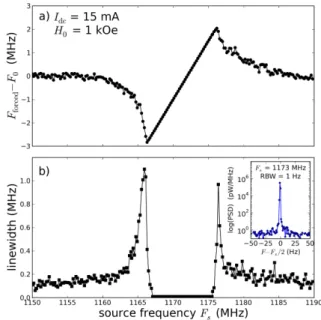
In order to measure the linewidth of the oscillator sig-nal when its frequency is locked, the source frequency Fs is now swept around 2F0. In Fig.2a, we plot the
frequency shift Fforced− F0 of the oscillator when it is
forced by the microwave field of amplitude hrf = 6.3 Oe
as a function of Fsvarying from 1150 MHz to 1190 MHz.
As in Fig.1a, we observe the characteristic behavior of synchronization to the external source, except that it is now at twice the oscillator frequency and the oscillation signal is not hindered by the source signal. Hence, we can analyze the dependence of the generation linewidth on Fs, which is plotted in Fig.2b. The striking
observa-tion is a dramatic reducobserva-tion of the generaobserva-tion linewidth within the locking range. As shown in the inset of Fig.2b, the measured linewidth is indeed limited by the 1 Hz minimal RBW of the spectrum analyzer, i.e., the auto-oscillation is perfectly phase-locked to the external source. This corresponds to an improvement of the sig-nal coherency by a factor greater than 105 with respect
to the free running case. The increase of the generation
FIG. 2. (color online) (a) Frequency shift Fforced− F0 and
(b) linewidth of the generated signal as a function of the fre-quency of the source (hrf= 6.3 Oe), swept around 2F0. The
inset displays a measurement in the locking range (spectrum analyzer RBW= 1 Hz).
linewidth up to 1 MHz observed at the boundaries of the locking range is attributed to successive synchronization-unsynchronization events occurring at the timescale of the measurement [29].
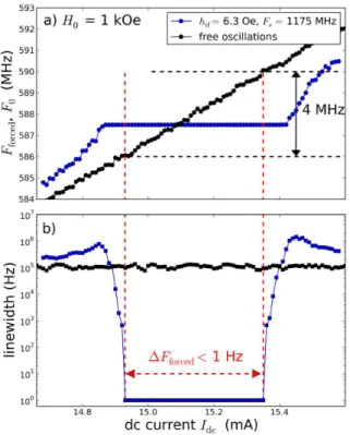
To gain further insight, we investigate the robustness of this perfect phase-locking. We now measure the auto-oscillation signal as a function of Idc, which is swept
from 14.6 mA to 15.6 mA. In the free regime (external source turned off), the generation frequency increases lin-early from 584 MHz to 592 MHz, while the linewidth is nearly constant around ∆F0 = 142 kHz, as shown by
the black dots in Figs.3a and b, respectively. The tun-ability observed in our vortex-based STNO, dF0/dIdc ≃
8 MHz/mA, results from the Oersted field created by the dc current [36]. In the forced regime with the external source turned on at Fs = 1175 MHz and hrf = 6.3 Oe
(see blue dots in Fig.3a), the auto-oscillation frequency is pulled towards half the source frequency Fs/2 for
Idc < 14.9 mA and Idc > 15.4 mA, and constant and
equal to Fs/2 in between these boundaries, which define
the locking range. The associated decrease of the genera-tion linewidth is spectacular, as shown by the logarithmic scale in Fig.3b. The measured linewidth is limited by the RBW = 1 Hz for 14.93 < Idc< 15.35 mA, which means
that the phase-locking to the external source is perfect within this range of current. The latter corresponds to a variation by 4 MHz of the auto-oscillation frequency in the free regime. These features demonstrate the ro-bustness of the synchronization observed in our sample, as it means that even if the external source frequency deviates from the oscillator frequency by more than ten
FIG. 3. (color online) Current dependence of the (a) STNO frequency and (b) generation linewidth in the free (black dots) and forced regimes (blue dots).
times the free running linewidth, perfect phase-locking can still occur.
Another issue to investigate is the influence of fluc-tuations [37] on the actual characteristics of our vortex oscillator when it is phase-locked. To do that, we com-pare the synchronization of auto-oscillation signals hav-ing different generation linewidths. We use two different applied fields, H0 = +1 kOe and H1 = −0.27 kOe, at
which the emission frequencies at Idc = 15 mA slightly
differ (F0 = 586 MHz and F1= 684 MHz, respectively),
and the generation linewidth varies by more than a fac-tor seven [38], from ∆F0= 142 kHz to ∆F1= 1.05 MHz
(see inset of Fig.4a). Using blue and red dots at H0
and H1, respectively, we plot the experimental frequency
mismatch Fforced− Fs/2 (Fig.4a) and the linewidth in
the forced regime (Fig.4b) as a function of the detun-ing F0,1− Fs/2 between the natural oscillator frequency
and half the source frequency [39]. The strong differences observed in the characteristics of the synchronization at these two fields reveal the role played by the fluctuations in the phase dynamics of STNOs. When the latter are weak (narrower generation linewidth at H0), the locking
range is large (more than 4 MHz) and the synchronized signal acquires the spectral quality of the source (less than 1 Hz). When the noise is larger (broader genera-tion linewidth at H1), it competes against the coupling
to the external source, which results in a smaller appar-ent locking range and a poorest spectral quality of the
FIG. 4. (a) Variation of the frequency mismatch Fforced−Fs/2
as a function of the detuning F0,1− Fs/2 at H0 = +1 kOe
(blue dots) and H1 = −0.27 kOe (red dots). The external
source amplitude is set to hrf = 6.3 Oe. Continuous lines
are fits using Eq.(5) of Ref.[27] yielding a coupling strength ε = 2.5 MHz. The inset shows the emission spectra at H0
and H1 in the free running regime. (b) Dependence of the
emission linewidth on the frequency detuning at H0 and H1.
forced oscillation. Here, increasing the linewidth by a factor ∆F1/∆F0 ≃ 7 has a huge influence on the signal
coherency in the phase-locked regime since its improve-ment with respect to the free running case drops from a factor 105 to only 10. The influence of phase
fluctu-ations on the frequency mismatch has been modeled by Eq.(5) of Ref.[27] (see continuous lines in Fig.4a). Using the measured linewidths ∆F0and ∆F1 in this equation,
the only fitting parameter is the coupling strength of the external microwave source to the oscillator (equal to half the locking range in the case of zero fluctuations), which is found to be ε = 2.5 MHz both at H0and H1.
In conclusion, we have shown that the microwave sig-nal generated by a STNO based on coupled vortices can be efficiently synchronized to an external microwave field. The relative locking range indeed exceeds 10% for small drive amplitudes (hrf ≃ 5 Oe) and the auto-oscillation
signal acquires the spectral purity of the source, corre-sponding to an improvement of its coherency by a factor greater than 105. Moreover, this perfect phase-locking is
robust, as it survives even when the external frequency deviates from the oscillator frequency by more than ten times its linewidth. We believe that the efficient synchro-nization of vortex-based STNOs to the microwave field
4 is very promising for the idea of mutually coupling such
oscillators through the dipolar interaction [40].
This research was partly funded by the French ANR (grant SPINNOVA ANR-11-NANO-0016) and the EU (FP7 grant MOSAIC ICT-FP7-317950).
∗ gregoire.deloubens@cea.fr
[1] S. I. Kiselev, J. C. Sankey, I. N. Krivorotov, N. C. Emley, R. J. Schoelkopf, R. A. Buhrman, and D. C. Ralph, Nature 425, 380 (2003).
[2] W. H. Rippard, M. R. Pufall, S. Kaka, S. E. Russek, and T. J. Silva, Phys. Rev. Lett. 92, 027201 (2004).
[3] D. Houssameddine, U. Ebels, B. Delat, B. Rodmacq, I. Firastrau, F. Ponthenier, M. Brunet, C. Thirion, J.-P. Michel, L. Prejbeanu-Buda, M.-C. Cyrille, O. Redon, and B. Dieny, Nature Mater. 6, 447 (2007).
[4] S. Bonetti, P. Muduli, F. Mancoff, and J. Akerman, Appl. Phys. Lett. 94, 102507 (2009).
[5] A. A. Tulapurkar, Y. Suzuki, A. Fukushima, H. Kub-ota, H. Maehara, K. Tsunekawa, D. D. Djayaprawira, N. Watanabe, and S. Yuasa, Nature 438, 339 (2005). [6] J. Zhu, J. A. Katine, G. E. Rowlands, Y.-J. Chen,
Z. Duan, J. G. Alzate, P. Upadhyaya, J. Langer, P. K. Amiri, K. L. Wang, and I. N. Krivorotov, Phys. Rev. Lett. 108, 197203 (2012).
[7] P. K. Muduli, Y. Pogoryelov, S. Bonetti, G. Consolo, F. Mancoff, and J. ˚Akerman, Phys. Rev. B 81, 140408 (2010).
[8] Y. Pogoryelov, P. K. Muduli, S. Bonetti, E. Iacocca, F. Mancoff, and J. ˚Akerman, Appl. Phys. Lett. 98, 192501 (2011).
[9] K. Mizushima, K. Kudo, T. Nagasawa, and R. Sato, Journal of Applied Physics 107, 063904 (2010).
[10] J.-G. Zhu and Y. Wang, IEEE Trans. Magn. 46, 751 (2010).
[11] V. S. Pribiag, I. N. Krivorotov, G. D. Fuchs, P. M. Bra-ganca, O. Ozatay, J. C. Sankey, D. C. Ralph, and R. A. Buhrman, Nature Phys. 3, 498 (2007).
[12] Q. Mistral, M. van Kampen, G. Hrkac, J.-V. Kim, T. De-volder, P. Crozat, C. Chappert, L. Lagae, and T. Schrefl, Phys. Rev. Lett. 100, 257201 (2008).
[13] K. Y. Guslienko, J. Nanosci. Nanotechnol. 8, 2745 (2008). [14] A. Dussaux, B. Georges, J. Grollier, V. Cros, A. Khvalkovskiy, A. Fukushima, M. Konoto, H. Kub-ota, K. Yakushiji, S. Yuasa, K. Zvezdin, K. Ando, and A. Fert, Nat. Commun. 1, 8 (2010).
[15] N. Locatelli, V. V. Naletov, J. Grollier, G. de Loubens, V. Cros, C. Deranlot, C. Ulysse, G. Faini, O. Klein, and A. Fert, Appl. Phys. Lett. 98, 062501 (2011).
[16] A. Slavin and V. Tiberkevich, IEEE Trans. Magn. 45, 1875 (2009).
[17] T. Shibata, R. Zhang, S. Levitan, D. Nikonov, and G. Bourianoff, in Cellular Nanoscale Networks and Their Applications (CNNA), 2012 13th International Work-shop on (2012) pp. 1–5.
[18] S. Kaka, M. R. Pufall, W. H. Rippard, T. J. Silva, S. E. Russek, and J. A. Katine, Nature (London) 437, 389 (2005).
[19] F. B. Mancoff, N. D. Rizzo, B. N. Engel, and S. Tehrani, Nature (London) 437, 393 (2005).
[20] S. Sani, J. Persson, S. Mohseni, Y. Pogoryelov, P. Muduli, A. Eklund, G. Malm, M. Kll, A. Dmitriev, and J. Akerman, Nature Communications 4, 2731 (2013). [21] A. Ruotolo, V. Cros, B. Georges, A. Dussaux, J. Grol-lier, C. Deranlot, R. Guillemet, K. Bouzehouane, S. Fusil, and A. Fert, Nature Nanotech. 4, 528 (2009).
[22] A. N. Slavin and V. S. Tiberkevich, Phys. Rev. B 72, 092407 (2005).
[23] J. Grollier, V. Cros, and A. Fert, Phys. Rev. B 73, 060409 (2006).
[24] A. D. Belanovsky, N. Locatelli, P. N. Skirdkov, F. A. Araujo, J. Grollier, K. A. Zvezdin, V. Cros, and A. K. Zvezdin, Phys. Rev. B 85, 100409 (2012).
[25] S. Erokhin and D. Berkov, arXiv:1302.0659.
[26] W. H. Rippard, M. R. Pufall, S. Kaka, T. J. Silva, S. E. Russek, and J. A. Katine, Phys. Rev. Lett. 95, 067203 (2005).
[27] B. Georges, J. Grollier, M. Darques, V. Cros, C. Der-anlot, B. Marcilhac, G. Faini, and A. Fert, Phys. Rev. Lett. 101, 017201 (2008).
[28] M. Quinsat, J. F. Sierra, I. Firastrau, V. Tiberke-vich, A. Slavin, D. Gusakova, L. D. Buda-Prejbeanu, M. Zarudniev, J.-P. Michel, U. Ebels, B. Dieny, M.-C. Cyrille, J. A. Katine, D. Mauri, and A. Zeltser, Appl. Phys. Lett. 98, 182503 (2011).
[29] A. Dussaux, A. V. Khvalkovskiy, J. Grollier, V. Cros, A. Fukushima, M. Konoto, H. Kubota, K. Yakushiji, S. Yuasa, K. Ando, and A. Fert, Appl. Phys. Lett. 98, 132506 (2011).
[30] S. Urazhdin, P. Tabor, V. Tiberkevich, and A. Slavin, Phys. Rev. Lett. 105, 104101 (2010).
[31] A. Hamadeh, G. de Loubens, V. V. Naletov, J. Grollier, C. Ulysse, V. Cros, and O. Klein, Phys. Rev. B 85, 140408 (2012).
[32] V. V. Naletov, G. de Loubens, G. Albuquerque, S. Bor-lenghi, V. Cros, G. Faini, J. Grollier, H. Hurdequint, N. Locatelli, B. Pigeau, A. N. Slavin, V. S. Tiberkevich, C. Ulysse, T. Valet, and O. Klein, Phys. Rev. B 84, 224423 (2011).
[33] V. Sluka, A. K´akay, A. M. Deac, D. E. B¨urgler, R. Hertel, and C. M. Schneider, Phys. Rev. B 86, 214422 (2012). [34] A. Hamadeh, G. de Loubens, O. Klein, V. Naletov,
N. Locatelli, R. Lebrun, J. Grollier, and V. Cros, arXiv:1310.4913.
[35] The output power from the synthetizer injected into the microwave antenna is set to P = 0 dBm.
[36] A. V. Khvalkovskiy, J. Grollier, A. Dussaux, K. A. Zvezdin, and V. Cros, Phys. Rev. B 80, 140401 (2009). [37] E. Grimaldi, A. Dussaux, P. Bortolotti, J. Grollier, G. Pillet, A. Fukushima, H. Kubota, K. Yakushiji, S. Yuasa, and V. Cros, arXiv:1311.6299.
[38] This change of linewidth is due to the influence of a lower frequency overdamped mode [34].
[39] In these measurements, hrf = 6.3 Oe and Idc is varied
from 14.6 mA to 15.6 mA. At H0, F0varies from 584 MHz
to 592 MHz and Fsis fixed to 1175 MHz. At H1, F1varies
from 681 MHz to 689 MHz and Fsis fixed to 1370 MHz.
[40] A. D. Belanovsky, N. Locatelli, P. N. Skirdkov, F. Abreu Araujo, K. A. Zvezdin, J. Grollier, V. Cros, and A. K. Zvezdin, Appl. Phys. Lett. 103, 122405 (2013).