HAL Id: cea-02435094
https://hal-cea.archives-ouvertes.fr/cea-02435094
Submitted on 10 Jan 2020HAL is a multi-disciplinary open access archive for the deposit and dissemination of sci-entific research documents, whether they are pub-lished or not. The documents may come from teaching and research institutions in France or abroad, or from public or private research centers.
L’archive ouverte pluridisciplinaire HAL, est destinée au dépôt et à la diffusion de documents scientifiques de niveau recherche, publiés ou non, émanant des établissements d’enseignement et de recherche français ou étrangers, des laboratoires publics ou privés.
basic design
F. Dechelette, C. Courcier, J. Hirn, H. Lorcet, K. Vulliez
To cite this version:
F. Dechelette, C. Courcier, J. Hirn, H. Lorcet, K. Vulliez. The fuel handling route of astrid at the beginning of the basic design. International Conference on Fast Reactors and Related Fuel Cycles: Next Generation Nuclear Systems for Sustainable Development (FR17), Jun 2017, Yekaterinburg, Russia. �cea-02435094�
The fuel handling route of ASTRID at the beginning of the basic design
F. Dechelette1, C. Courcier2, J. Hirn2, H. Lorcet1, K. Vulliez3 1
Commissariat à l’Energie Atomique et aux Energies Alternatives (CEA), Cadarache, France 2
AREVA NP, Lyon, France 3
Commissariat à l’Energie Atomique et aux Energies Alternatives (CEA), laboratoire d’étanchéité, Bagnols sur Cèze, France
E-mail contact of main author: franck.dechelette@cea.fr
Abstract. At the beginning of the Basic Design phases of ASTRID starting in 2016, the entire
fuel handling route has been challenged in order to improve some aspects like availability and investment cost. Especially, studies performed at the end of preliminary design (2010 – 2015) phase show that the availability target will be difficult to obtain with a significant risk of malfunction because of multiple handling operations in series. Two main changes have been then decided: the implementation of an sodium external buffer zone, similar with an in-sodium external storage but associated with an in-primary vessel storage to reduce its size and its allowable residual power, and the merging of the fresh subassembly storage with the spent fuel subassembly storage which allows both reduction of size and number of equipment. These new options have the first advantages to reduce drastically the number of operations that have to be done during scheduled outage and to minimize the overall Balance Of Plant. After description of the entire fuel handling route adopted for ASTRID, this paper aims at identifying the advantages of this new option and points the remaining issues or questions that will be studied in details during the current Basic Design phase.
Key Words: ASTRID, Fuel handling Route, optimization 1. The fuel handling route at the end of the 2015
At the end of AVP2 phase, the fuel handling route of ASTRID is based on an on-line handling, with gas cask which transfers directly fuel subassemblies from the reactor vessel to the washing pits, without intermediate storage. The subassemblies spent one cycle in in-core storage, and then are transferred with a reasonable thermal power.
However, the fuel handling system presents the following limits:
- The fuel handling rate : the fuel subassembly loading / unloading takes 215 minutes, and consequently, the theoretical fuel handling rate is 14.5 days for a core management frequency of 4, extrapolated at 19.7 days for a frequency of 3 (without considering uncertainties),
- The reliability of the fuel handling system may be risky : 15 in series equipment and 27 subsequences are needed for one loading/unloading. The dedicated working group has confirm this unavailability risk and in particular, the operation lead with the isolating valve and the operation of rise and download,
- The in series fuel subassembly management during the reactor shutdown, between the primary vessel and the washing pits, presents disadvantages due to experimentation needs and starting core phases,
- The fuel handling building size is large (110m) and some equipment is doubled.
To improve performances of the fuel handling route, 2 main topics have been studied and challenged at the beginning of 2016, during the 6 first months:
1. The implementation of an external storage to uncouple the primary and secondary fuel handling operation. Contrary to AVP1 external storage, the objective is to optimize and reduce as much as possible the capacity, including an internal storage for decay heat removal of irradiated subassembly. The external storage, named “external buffer zone”, may be then simplified in order to optimize its cost,
2. The fuel loading/unloading mechanisms, impacted by the adjunction of the external storage,
The fuel handling system finally retained is described in this paper.
FIG. 1. Fuel handling scope.
The scope and main specification of the fuel handling route are recall below: 1. Store fresh subassembly before loading into the core [5]
- Capacity of 1 core for the first loading then, one loading during operation - Controls performed during reception before storage
2. Prepare fresh subassembly for the loading
- Dedicated pit needed – Removal of oxygen and impurities 3. Load and unload subassembly into the core
- In sodium transfer including heat removal
- Core frequency = 4, which involves 72 subassemblies, 5 control rods and some experimental and failed fuels
4. Clean spent fuel subassembly: remove residual sodium on wetted surfaces - Remove sodium before in-water storage and evacuation
5. Store used fuel for decreasing heat power
- Capacity of 3 complete cores (~ 900 fuel subassemblies)
A specific route for some components is also needed. This is the case for the absorber elements of the core like the Upper Neutron Shielding (UNS) or the control rod: as they are not sealed, sodium gets inside the absorber pins containing boron carbide and residual sodium remains inside them even after dripping. (cf. § 4). This issue avoids the immersion step in washing pits and only atomization is possible. In the case of UNS, it means to remove them from subassembly before this immersion step. Moreover, the experimental devices and the failed fuel subassemblies (open clad failure) need specific treatment and are then directly transferred in the hot cell without complete cleaning.
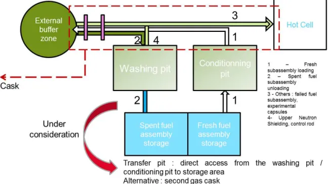
FIG. 2. Principle of the ASTRID’s Fuel Handling Route 2. The main fuel handling systems
The different fuel handling mechanisms are described below.
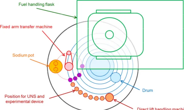
2.1.- In-vessel transfer machines
Based on well-known components, the principle is to load / unload the subassemblies with two rotating plugs, one direct lift charge machine into the little rotating plug and one fixed arm charge machine on the large rotating plug. This kind of machines has been used on several projects in the past with a positive feedback. The main topics of innovation in this part are the dynamic seals for rotating plug and the offset of the fixed arm machine (more than 2 meters), that enforces manufacturing concerns and study.
2.2.- The primary vessel refueling machine
The principle retained is a concept with two ramps and a loading/unloading airlock. The system transfers the subassemblies into a double position sodium pot filled with sodium. The maximum subassembly power for this transfer is about 40kW. The double position sodium pot has been chosen to optimize the availability factor, by exchanging fresh fuel and spent fuel in primary and buffer zone vessels. This device takes opportunity to operate in parallel ramps transfer and in vessels transfer. The duration of one cycle transfer (go/return) of a sodium pot is then optimized.
The system integrates a concept of double isolating valve between the cover gas of primary vessel and the external buffer zone.
Some specific studies for the basic design are then needed:
- If the concept of ramp is well known, the loading/unloading lock swing concept has to be developed,
- Integration of the ramp induces modification of the inner vessel and reactor slab arrangement – this also induces reduction of core Lateral Neutron Shielding capacity,
- Integration of the transfer lock and its exceptional removal induces specific constraints on civil work.
2.3.- The external buffer zone
The specifications that we can provide for this external buffer zone are:
- In sodium buffer zone in order to reduce number of operation performed during a reactor shutdown,
- Maximum residual power: 300 kW,
- Number of positions in the case of core frequency of 4 : 72 subassemblies + 5 Control rods + failed fuels + experimental devices, so a number of 85 positions; to be compatible with a core management frequency of 3, the target is fixed at 110 positions,
- Diameter to be confirmed but limited ≤ 5m,
- One specific device to remove the Upper Neutron Shielding and experimental capsules,
- Simplify as much as possible the circuits and take benefit of the thermal inertia of the system.
The concept adopted is a carrousel type. To improve its size, some absorber rods are implemented (the network pitch is then reduced from 58cm to about 23cm). Because of the angle of the ramp, a specific arrangement of vessels is needed and has to be studied. The handling inside the vessel is then performed with the rotation of the carousel and one fixed arm charge machine.
The priority items for the future work is the consolidation of the size, number of position, global geometry and general arrangement and in another hand the thermomechanical behavior of the vessel especially with the non-axisymmetric part due to the ramp.
Concerning the circuits, ASTRID’s reference is one circuit dedicated to the filling/draining/cleaning of the sodium and the residual power heat removal in normal conditions and a second circuit to remove the residual power (Decay Heat Removal) in incidental and accidental conditions. Some specific devices are also installed inside the vessel to heat the sodium.
FIG. 4. Circuits associated with the External Buffer Zone
A future work, dedicated to the optimization of the circuits, including analyses of design opportunity for controlling or reducing cost is planned.
For safety consideration, the guidelines are listed below:
- Objective of non-fusion of subassembly: the active cooling system and the thermal inertia of the buffer zone allows in case of loss of all cooling devices to prevent the fusion of the subassembly. The non-fusion of a blocked subassembly is also assumed,
- Active cooling devices DHR design with an objective of availability and reparability: The thermal inertia gives delays to repair (more than 1 month to obtain a sodium temperature of 450°C, new calculations are under progress),
- The DHR architecture is expected as one system for normal operation and one system for accidental situation, used in case of loss of the first system, designed as safety class. The priorities for the future work associated with this safety subject are to confirm the strategy and equipment implemented and to look for a possible cliff effect associated with the decrease of the residual power.
2.4.- Post external buffer zone transfer cask and transfer pit
A cask is used to transfer fresh and spent subassemblies between conditioning pits / buffer zone and buffer zone / washing pits. This cask is soiled with sodium, and integrates active cooling system to prevent failed pin in case of blockage. The maximum subassembly power is 3 kW to prevent fuel melt in case of loss of active cooling.
FIG. 3. Post ZTE subassembly transfers
To transfer subassembly between storage and pits, two alternatives are under consideration: a second gas cask or some pits design adaptation to ensure a direct access from the pits to the storage area.
Because of the use of an unsealed UNS, after irradiation, residual sodium may remain inside the absorber pins, even after dripping. The estimation of residual sodium inside each UNS leads to significant amount, up to 400 g. Some studies are still performed to reduce this amount but at that time the pin cannot be immersed in water. Then, they are inserted into containers and transferred directly from the ZTE to the hot cell to be treated. The control rods are atomized into the washing pits (first phase of washing) and transferred into the hot cell. The principal items for R&D on these topics are then the study of adapted washing process of B4C components and the work to reduce the inventory of sodium before cleaning.
An alternative of this point is to adopt a leak-tight type UNS but this option is currently not in accordance with ASTRID specifications on core design and need long term development.
2.5.Containment management
One of the consequences of those fuel handling options is the integration inside the reactor building of the external buffer zone. Then, the fuel handling operations are performed in 2 steps:
- During reactor shutdown, transfer between primary vessel / external buffer zone, - During reactor operation, transfer between external buffer zone / pits / storage and hot cell.
This requires an access inside the containment building during operation. To make this access possible, different compartments are implemented: the reactor zone, the external buffer zone (separated with the reactor zone) and the airlock zone and the double door access to the fuel building. The utilization of the airlock is assumed during reactor operation.
The airlock must not reduce the performance of the reactor building containment, and then, design requirements on airlock to guarantee containment performances are integrated, such as specific procedure to control sealing, one door open at a time, adapted sealing and ventilation of the airlock.
It can be noticed that behind the airlock remains the fuel building and its nuclear containment. Some study may continue on this topic to confirm the strategy, especially the design of the Airlock.
3. Research and development studies
Research and development studies are carried out to support technical Fuel Handling System’s studies. Particular attention is being paid on two main fields in order to improve performances, costs and ASTRID’s delay: firstly, washing operations to treat sodium in the case of complex geometries and secondly, static and dynamic seals for rotating plugs. These two points are detailed into the following paragraphs.
3.1 Innovative studies on washing operations:
Based on Phenix and Superphenix’s feedback [1, 2], ASTRID’s cleaning pit has been designed regarding two main processes:
- The historic cleaning one, based on the injection of a mist, sprayed into carbon dioxide as carrier gas. It is swept through the fuel subassembly to treat sodium and, in the same time, to cool it down to avoid corrosion risk. This process has shown its ability and its reliability to safely treat sodium in the case of geometries allowing the mist to pass through without any risk of condensation. So, classical fuel subassemblies will be washed with this reference process.
- A slow immersion process in order to increase the capacity of the cleaning pit to treat other geometries and in particular more complicated designs.
Some studies are underway regarding other type of subassemblies: indeed, because of complex geometry and/or sodium’s retentions remaining even after draining operation, these elements can be difficult to clean. It is particularly the case of all neutron absorber elements that are not sealed (subassemblies and Upper Neutron Shielding (UNS)).
Firstly, R&D studies include optimizing the design of neutron absorber pins to improve the draining of main sodium retentions and limit the quantity of residual sodium before cleaning. Dedicated sodium experiments will be realized within the next few years in order to evaluate the capacity of each studied design to drain sodium contained into the absorber pins.
Secondly, this R&D work also involves the improvement of the cleaning processes itself with two main remaining questions:
1. Considering ASTRID’s design, is it possible to treat external sodium present on absorber elements by the classical process without any risks in regards to sodium water reaction in order to facilitate their handling in the hot cells?
This point will be studied by conducting experimental draining and cleaning tests on representative mock-up of absorber pins. Depending on the results, some innovative solutions will be proposed.
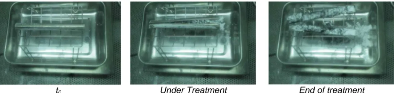
For this second item, we can refer to the previous patent proposed by Godlewski [3] : it describes a treatment process based on several steps. Firstly, a cutting operation is realized on the sheath to ensure access to the sodium of the reactive agents.
t0 Under Treatment End of treatment
FIG. 3. Illustration of the carbonation treatment of sodium contained into a mock-up of absorber pins
Secondly, the so prepared pins are introduced into a facility where a carbonation treatment is realized. The pins are subjected to a gas mixture composed of water steam, carbon dioxide and nitrogen to transform metallic sodium into solid sodium carbonates (Na2CO3 and NaHCO3 forms). The volume occupied by carbonates is larger than the volume initially occupied by sodium. So, their expansion cause the opening of the sheath, as well as the carbonation reaction propagates within the whole pin and treats the whole accessible sodium.
3.2 Innovative solutions for the sealing of ASTRID rotating plugs:
ASTRID’s reactor slab is equipped with two Rotating Plugs (RP), that provide access into the reactor core to perform loading/unloading operations. On most of existing Fast Breeder Reactor (FBR), the rotating seal ensuring the first leak-tightness barrier is made of fusible metal, melted during handling phase and solidified during reactor operation. Maintenance issues and technical hazards observed on several FBR, leads to study new design concepts without metallic seal. In the framework of ASTRID project, innovative concepts have been proposed to replace the liquid metal and cope with all the most generics RP design constraints. The proposed solution, based on elastomer seals, combine an inflatable seal and a massive seal. Both seals, mounted side-by-side, are operating in the axial direction providing independent functions. In this design the dynamic sealing of the reactor vessel cover gas during the up/down vertical movements of the RP is ensure by the inflatable seal, while the double lips-seals (inverted-π shape) compressed at the end of the translation ensure the sealing during the RP rotation. To support and qualify this concept in relevant conditions, a large scale mock-up was build [4].
FIG. 4. Left : The Rotary Plug Test-stand. Right: The two seals proposed mounted in their groove 4. Performances of the fuel handling route and key points
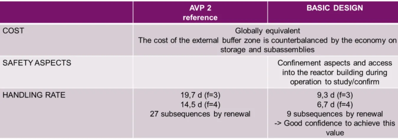
The performances of the fuel handling route have been evaluated according to the 3 following markers: the availability, the safety and the cost. The principal conclusions are:
- Availability: one fuel subassembly is exchanged in 95 minutes. The consequences are 6.7 days for a fuel handling campaign (core frequency of 4). The exploitation team is also limited.
- Safety: the low residual power of the external buffer zone (maximum 300 kW) and the large delay to achieve high temperature on structure (>1 month) must allow simple safety system to control and remove the residual power. The choice of an external buffer zone inside the reactor building makes necessary to work on topics related to in-operation regular access inside the reactor building in order to define conception rules to make this access acceptable. We can also notice that the external buffer zone allows a Whole Core Discharge of about 1 year.
- Cost: the cost of the external buffer zone is limited because of its low power, low capacity and low size. This buffer zone also allows to suppress some washing pits and to simplify the fuel handling route. The number of subassemblies (~100) used during the starting phases is also reduced. As a conclusion regarding costs, we can say that the cost associated with the buffer zone is globally counterbalanced with the economy of subassembly and simplification on the fuel handling route.
TABLE I: KEY MARKERS PERFORMANCES
The points that are identified as key points for future work are:
1) Confirmation of the containment aspects and safety analysis associated – Airlock 2) Confirmation of the characteristics and circuits / components of the external buffer zone
5. Bibliography
1. Prele, G., et al., Review and innovative technologies on fuel handling systems for sodium cooled fast reactors, in Technical Meeting on Fuel Handling Systems of Sodium Cooled Fast Reactors,2008, IAEA’s Nuclear Energy Department’s.
2. Prele, G., et al. Some experimental feedback of the fuel handling system of French sodium fast reactors regarding specific operations : cleaning, refuelling, final defuelling in IGCAR - Technical Meeting on Fuel Handling Systems of Sodium Cooled Fast Reactors. 2008. Kalpakkam, Tamil Nadu, India: IAEA’s Nuclear Energy Department’s.
3. Godlewski, J., et al.,Method for treating an absorber pin containing contaminated boron carbide and sodium, (WO 2015004382 A1),CEA, 2013.
4. Vulliez, K., et al. Experimental qualifications of rotatable plug seals for sodium fast reactor on a large scale test stand (IAEA-CN-245-24) in FR17. 2017. Yekaterinburg, Russian Federation
5. Grouiller, J.P.; et al., Plutonium recycling capabilities of ASTRID reactor (IAEA-CN-245-348) in FR17. 2017. Yekaterinburg, Russian Federation