ON THE BASIS OF MAINTENANCE REQUIREMENTS by
TAKASHI UCHIKAWA
2
DESIGN STUDY OF TOIRSATRON POWER REACTORS ON THE BASIS OF MAINTENANCE REQUIREMiTS
by
TAKASHI UCHIKAWA
Submitted to the Department of Nuclear Engineering
on May 9, 1980 in partial fulfillment of the
requirements for the Degree of Master of Science in Nuclear Engineering.
ABSTRACT
Conceptual design study of a Torsatron power reactor (M.I.T.'s T-1 Reactor) is done with special emphasis givan to questions of maintenance. It includes investigations and designs of superconducting magnet windings, blanket, vacuum/exhaust systems, vessel structures, and reactor layout, as well as investigations of maintenance procedures.
T-1 Reactor has several inherent advantages such as large aspect ratio which provides an ample space around the reactor, steady-state reactor operation, natural divertor. On the other hand, the helical magnet windings is another feature of this reactor, which gives rise to complications of reactor structures and maintenance procedures. Based on these characteristics of Torsatron reactors, this study has examined and developed the modular
reactor concept of T-1 Reactor proposed by the preceding work at M.I.T..
Thesis Supervisor: Dr. Iawrence M. Lidsky
Acknowledgements
I would like to express my deep gratitude to Professor Lidsky for
his continual encouragement and guidance throughout this study.
I also
thank Professor Politzer for his help and useful suggestions given to mesince I first attended M.I.T.
I will give special thanks to my employer, Mitsubishi Heavy Industries,
Ltd., who gave me the opportunity of studying abroad at M.I.T. as a
graduate student.
Ms. Cathy Lydon at Professor Lidsky's office and John Aspinal also
deserve a great appreciation for their kind oare and aid.
Finally, my wife Akemi and my daughter Waka well understood my situation and put up with graduate student life. I would like to express my thanks to them both.
4
TABLE OF CONTENTS TITIZ PAGE ...1
ABSTRACT ... 2 AaGOWIEDGEMETS
..... ...e... ...3
TABIE OFCONTENTS
...4
LIST OF FIGURES ... ooo*. *oo*.... *..*... 7
LIST OF TABLES ... ...
9
NOMENCLATURE ... 10
1
. INTRODUCTION ...14
1.1 PURPOSE OF STUDY ...
14
1.2 MAIN FEATURES OF T-1 REACTOR ... 15
2. SUPERCONDUCTING MAGNET WINDINGS ... ... ... 17
2.1
GENERAL ... 172.2 SELECTION OF 00LING METHODS ... 18
2.3 CRYOGENIC DESIGN OF THE MAGNETS ... 21
a.CONDUCTOR ... 21
b. CRYOSTAT DESIGN AND
REQUIRED
REFRIGERATION POWER ... 21c. CONDUCTOR
COOLING
...32
2.4
MAGNET JOINTS ...43
a. PRESSURE CONTACTS ... ... ... ... . ...
43
b.
HEAT REMOVAL ... ... . 49c. SLIDING MOVEMENT ... e...
49
3.
THERMAL-HYDRAULIC DESIGN OF BLANKET ...59
3.1 GENERAL ...
59
3.2
HELIUM GAS COOLED BLANKET ...61
as
GENERAL
...61
b. T-1 REACTOR BLANKET DESIGN ... 64
c.
OMPARISON
OF HE-GAS-COOLING DESIGN PARAMETERS ... 83FOR HTGR AND T-1 REACTOR
3.3
LIQUID LITHIUM COOLED BLANKET ...85
a. GENERAL ... 85
b. THERMAL-HYDRAULIC DESIGN CONSIDERATIONS FOR T-1 RACTOR ... 86
4. DESIGN OF VACUUM/EXHAUST SYSTEM ...
99
4.1 VESSEL EVACUATION ...
99
a. GENERAL ONSIDERATIONS ... ...
99
b.
VACUUM PUMPING REQUIREOENT
... 1004.2 EXHAUST CONDITIONS OF D-T GAS AND HELIUM GAS ... 103
4.3
VACUUM/EXHAUST SYSTEM ... 109a. PUMPING SYSTEM ...
109
b. PARTICLE COLLECTORS ... s..e.
114
5.
REACTOR STRUCTURES ... 1165.1
VESSEL
STRUCTURES ... 116a. TOROIDAL VESSEL ...
116
b. VESSEL JOINTS ... 121
5.2
MAGNET SUPPORS ... 1246.
REACTORLAYOUT
AND MAINTENANCE ... .. ... ... 1286
6.2 DISASSEIMLY OF MAGNtETI WINDINGS *....*... e... ..
131
6.3 -REACrOR lAYOUT ... *****... of.* 0 00 137
6.4
?IAiNTElrAN
PRocEDuREs .*... ... 1477. MAIN~
RMULTS
. . . . . . .. .. .. .. .. . . . . ... .. .. .. .. .. . .. .. ... 153LIST OF FIGURES
FIGURE
2.3.1
Cable-in-conduit type conductor ...22
2.3.2
Internal cooling conductor ...
23
2.3.3
a)
Single-superinsulation cryostat ...
24
2.3.3 b) Double-superinsulation cryostat ... 24
2.3.4
fk
dT of glass epoxy
...28
2.4.1
Structure of the end part of magnet segment ... 442.4.2
Structure of the
end
part of conductor plates ...
45
2.4.3
Jumper conductor
...46
2.4.4 Refrigeration power required to cool magnet joints ... 48
2.5.1
Cooling-down time of superconducting magnet windings ...
57
3.2.1
Examples of helium gas cooled blanket designs
...63
3.2.2
Cross-sectional configulations of blanket modules
...
66
3.2.3 a) Type-A blanket modules
...67
3.2.3
b) Type-B blanket modules ...67
3.2.4
Film temperature drop in Type-A blanket
mokule
...
70
3.2.5
Pressure drop and required pumping power in Type-A
blanket
...
73
3.2.6
Cross-sectional view of channel arrangement
in Type-A blanket module ...
74
3.2.7
Spatial distribution of heat generation rate
in Type-A blanket module ...75
3.2.8
Film temperature drop in the blanket parts
of Type-B modules ... 773.2.9
Pressure drop and required pumping power in the blanket
parts of Type-B modules ... 793.2.10
Film temperatu-e drop in the particle collector parts
of Type-B modules ... 818
3.2.11
Pressure drop and required pumping power in the particle collector parts of Type-B modules3.3.1
Pressure drop and required pumping power in
Type-A
liquid Li cooled blanket with N
380
3.3.2
Pressure drop and required pumping power in Type-A
liquid Li cooled blanket with Na = 100 ...
3.3.3
Cross-sectional view of
3.5
cm O.D. tube arrangement
in
a
Type-A blanket module with
N
=
100
...
3.3.4
Spatial distribution of heat
generation rate
in the blanket
4.2.1
Conductance for exhaust gas
...
4.3.1
Diffusion pumping system
4.3.2
Cryopumping system ...4.3.3
Configurations of particle collectors and exhaust
ports
.. .. * . .. ... *...5.1.1
Cross-sectional view of vessel
5.1.2
Toroidal shell subject to external pressure
5.1.3 Vessel shell loaded by own weight
5.1.4
Cross-sectional view of bellows joint
...
5.2.1
Support structures of superconducting magnet windings
5.2.2
Temperature profile in magnet support elements
6.2.1
Horizontal plane view of helical magnet windings
6.2.2
Vertical plane view of magnet windings
...
a)
-
g)
6.3.1
6.3.2 a)
6.3.2
b)
6.3.3
6.3.4
6.3.5
Composition of T-1 Reactor module ...
Configuration of vacuum/exhaust ports and NBI ports
....Confirutation of vacuum/exhaust ports ...
Vertical plane view of T-1 Reactor layout
Horizontal plane view of T-1 Reactor layout
Concept of plant arrangement82
94
95
97
98
107
110
111
115
n7
118
120
122
125
126
132
133
139
140
141
142
143
146
LIST OF TABLES
TABIE
1.2.1 Characteristics of T-1 Reactor... 16
2.1.1 mracteristics of superconducting magnet windings ... 17
2.2.1 Evaluation of cooling methods ... 20
2.3.1 Conducting heat loads ... 26
2.3.2 Radiation heat loads ... 29
2.3.3
Required refrigeration power
...31
2.3.4
Two-phase helium coolant conditions ...34
2.3.5 Friction pressure drop in cooling channels ... 38
2.3.6 Total pressure drop in cooling channels ...
41
2.5.1 Specific heat at cryogenic temperature ...
53
2.5.2
Calculation of cooling-down time ... 543.2.1
Comparison of first wall/blanket design parameters ...62
3.2.2 Thermal-hydraulic design parameters of proposed
T-1 Reactor blanket
...65
3.2.3 Comparison of He-gas-cooling design parameters for
HTGR
and T-1 Reactor ...84
4.1.1
Surface treatment and out-gassing rate of stainles
steel ... 1014.2.1
Design conditions of the exhaust system ...103
4.2.2 Required minimum duct-size as a function of duct length 108 4.3.1 Main design parameters of particle collectors ...
114
5.1.1 Design parameters of the vessel structures ... 116
6.1.1
Estimated weight of reactor module ...130
6.4.1 Plans and conditions of periodic first wall/blanket replacement ... *. ... 147
6.4.2
Time-table of first wall/blanket replacement
10
NOMENCIATURE
A Cross-sectional area
Surface area
A
0Heat conducting area
A
Surface area in vacuum space
6
AU
Heat transfer area in an unit cell
a
Half height of a rectangular duct in B
1direction
B
Magnetic field
B//
Magnetic field component parallel to flow
BL
Magnetic field component transverse to flow
C Specific heat
Conductance
C
Specific heat at constant volume
C
Coefficient of performance of refrigeration system
D Diameter
E
Young's modulus
F
Force
f Friction factor G Mass flux go Acceleration of gravityHa
Hartaann number
h
Heat transfer coefficient
h lCalculated heat transfer coefficient hc Forced flow heat transfer component
hb
Boiling flow heat transfer component
Ah Difference of enthalpyI
Current
I Current in each conductor plate
Iu
.Current in an unit cell
J Current density
K
loss of coefficient
Kcon
Sudden contraction-loss coefficient
Kelb Friction-loss coefficient for an elbow K Sudden expansion-loss coefficient
k Thermal conductivity
L Iongth
Thickness
AL
Thermal contraction length
N
Mass
Molecular weight Moment
I
Mass flow rate
a
Mass flow rateN
Number of elements
N Number of contact surfaces
Nu
Nusselt number
P
Pressure
p Pressure PC Contact pressurePr
Prandtl number
16P
Pressure drop
16Pa Acceleration pressure drop AO Contraction pressure drop Apf Friction pressure drop
Q
Heat loadGas flow
Qc
Conducting heat load
q,
Heat leakQm
Heat generation rate in a module
Qr
Refrigeration heat loadQU
Ohmic heat in an unit cell
q
Heat flux
c.
Required heat flux in conductor
qg
Out-gassing rate
R
Gas constant
Re
Reynolds number
RU Electrical resistance of an unit cell
12
S Pumping speed
Stress intensity
S 0Contact
surface area
S
Effective pumping speed
S Required pumping speed
Su
Cross-sectional area of an unit cell
S
0Maximum allowable stress intensity
T Temperature
&Tf Film temperature drop
t Time
Thickness
t, Wall thickness
Aft Cooling time
V Velocity
V
Velocity of liquid
V Velocity of vapor
Specific volume of liquid Specific volume of vapor
W Pumping power
Wr
Refrigeration power
w Weight x Quality Z Section modulus0(
Void fraction
Strain
Ratio of effetive contact area to total surface area Friction coefficient
Viscosity Pitch angle
Density
Electrical resistivity of copper Density of liquid
Density of vapor
6'
Electrical conductivity
6'0
Allowable stress
Energy confinement time
9
Two-phase friction multiplier
(Subscripts)
ave Averagef
Liquid
g
Vapor
h High1
Low
in
Inlet
out
Outlet
e Exitw
all
1 Region 1 2 Region 214
1.
Introduction
1.1 Purpose of Study
Compared with Tokamaks, Torsatron fusion reactors have substantially different engineering features; that is, helical magnet windings, large
aspect ratio, steady-state reactor operation, natural divertors, etc..
The first Torsatron reactor (MIT's T-1 Reactor) study showed that there are remarkable inherent advantages based on some of the above features, as well as obvious complications formed by helically wound magnets.
In developing conceptual design of fusion reactors in general,
maintainability or serviceability of the reactors is one of major concerns because the first wall/blanket structures will need periodic replacement which will require either disassembly of the basic reactor structures or complicated remote operation, and because the large capital cost of the reactors will require that down-time for both scheduled and unscheduled maintenance be kept to a minimum in order to increase availability.
This study investigates conceptual reactor designs for a Torsatron power reactor (T-1 Reactor) with special emphasis given to questions of maintenance. Specifically it includes investigation and design of super-conducting magnet windings, blanket, vacuum/exhaust system, vessel joints and other reactor structures, and reactor layout, as well as investigation of maintenance procedures.
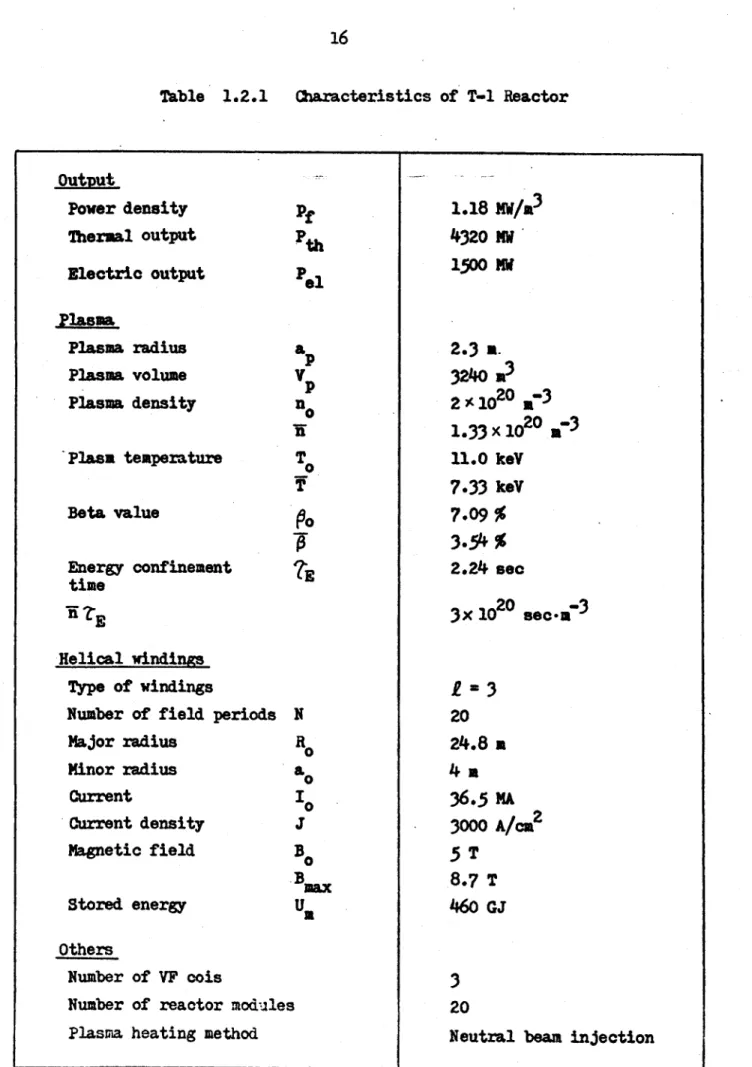
1.2
Main Features of T-1 Reactor
T-1 Reactor is a Torsatron power reactor producing about 1500 MW .
As MIT's repor -describes, the Torsatron is a steady-state toroidal magnetic
trap in which both the toroidal and poloidal magnetic field components are generated by a set of helical magnet windings; the internal magnetictopology of a Torsatron is similar to that of a Stellarator; the magnet coil structure, however, is much simpler in a Torsatron since separate toroidal field coils are not needed, and the helical windings are unidirectional.
In T-1 Reactor three circular coils are used to compensate vertical fields generated by the helical conductors bent into a torus. By selecting a suitable winding law the helical conductors can be significantly "force-reduced". The Torsatron configuration provides a natural divertor without any divertor coils. Since an externally driven plasma current is not required, the Torsatron can operate as a steady-state, ignited reactor. No coils, other than the helical and compensating windings are needed. Both plasma physics and reactor engineering considerations lead to the choice of a moderate aspect ratio for the Torsatron. In T-1 Reactor the aspect ratio of the helical
windings is about 6; the major radius is about 25 m and the minor radius is
4 a. The reactor structures are composed of 20 modules and the
superconduct-ing helical windsuperconduct-ings are connected from module to module with normally
conducting joints.
Thus T-1 Reactor is a steady-state, ignited, modular power reactor.
Fundamental parameters of T-1 Reactor are given in Table 1.2.1.
16
Table 1.2.1
Characteristics of T-1 Reactor
Output
Power density
Thermal output
Electric output
Plasma
Plasma radius
Plasma volume
Plasma density
Plasm temperatureBeta value
Energy confinement
time
7K
E-Helical windings
Type of windings
Number of field periods
Major radius
Minor radius
Current
Current density
Magnetic field
Stored energy
Others NumberNumber
PlasmaPf
Pth
Pe
a
VP
no
WT
ZE Na
01
0
J
Bo
Bmax Us of VF cois of reactor modules heating method1.18
4320
1500
MW/A
3MW
MW
2.3
a.
3240 m3
2
A1020 a-
31.33
x1020
-3
11.0 keY
7.33
keV
7.09%
3.54%
2.24 sec
3x 10²⁰ sec-mi
3I z 3
20
24.8 a
4 m
36.5
mA
3000 A/cz
25 T
8.7 T
460
GJ
3
20
2. Superconducting Nagnet Windings
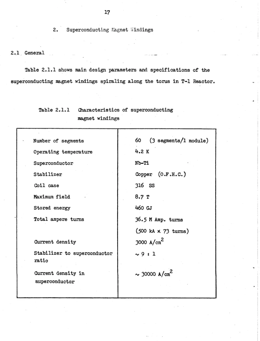
2.1 General
Table 2.1.1 shows main design parameters and specifications of the superconducting magnet windings spiraling along the torus in T-1 Reactor.
Table 2.1.1 Characteristics of superconducting magnet windings Number of segments Operating temperature Superconductor Stabilizer Coil case Maximum field Stored energy Total ampere turns
Current density Stabilizer to superconductor
ratio
Current density in superconductor60
(3
segments/i module)
4.2 K
Nb-Ti
Copper (o.F.H.C.)
316
SS
8.7 T
460 GJ
36.5 M Amp. turns
(500 kA
x
73
turns)
3000
A/cm
2-.,9 : 1
PV30000 A/cm
218
2.2 Selection of Cooling Methods
There are several cooling methods which are proposed to apply to fusion magnets:
1) Pool boiling of liquid helium
2) Cooling by superfluid helium (He-II)
3)
Forced circulation of supercritical helium 4) Forced circulation of subcooled helium5)
Forced circulation of two-phase helium.The pool boiling method has been proved to be successful for small systems; however, it seems to have serious disadvantages in its application to large magnets. Since large magnets have long and narrow cooling channels, it would be difficult to remove bubbles generated in the channels, particu-larly in the horizontal parts. The remaining bubbles would cause large reduction of nucleate boiling heat flux.
The cooling by superfluid helium provides some remarkable advantages, such as higher heat flux, higher magnetic field, higher current density. However, it also has several disadvantages:
a) Convective resistance in narrow and long cooling channels will be very large and limit the theoretical advantages.
b) The cost of refrigerating systems will increase noticeably due to extremely low temperature (1.8 K) refrigeration.
c) Complicated cryostats will be required d) Severe requirement for sealing is expected.
and complexity of cryostats, this cooling method does not seem to be most prospective.
According to G. Pasotti and M. Spadoni GNEN), the forced circulation of helium shows a number of advantages:
1) Effective heat removal from the magnets
2) Mass flow rate can be adjusted to obtain the desired heat flux.
3)
Design of the cryostats is greatly sumplified4) It is easier to achieve a good mechanical stiffness
[3-73
Comparative evaluation of the various cooling methods is summerized in Table 2.2.1. In this study, we select two options of probable methods: forced circulation of supercritical helium and forced circulation of two-phase helium. The former one has advantages of ease of handling, simple
cryostats, small inventry of helium coolant, etc.. It also has a few disadvantages, among which low heat flux and low cooling power is most
concerned. Some experimental studies are being done, at MIT and other places, to examine cryostability of superconducting magnets cooled by this method.
The latter, forced circulation of two-phase helium has a relatively high heat transfer coefficient and a large cooling power without
tempera-ture increase; however, two-phase helium flow has the possibility of flow separation and instability in flow distribution. Recently some operation
experience of a large superconducting dipole cooled by forced circulation
[8J
of two-phase helium has been reported from CERN, but still it will need a further experimental reseach and development to examine the feasibility of this method.
20
s0 hrO F4 1.. ft. alr Cd 4) 0 pq 0) Sh H Cd . 0 0 0 0 E)0 $9 0 0 r 0 0l o 0 3 bDH 0 O 0 )0 114 'Or 03 cd Q 0 G) pd4~ Cd P, k4+) + 0 43 W ) 4 0 r. P4~ 0 0 p4 0)4) 0 0 bCH 0 -. 4 9 24 0 P H to j o o -IH 21 41 > 04 0 to- 0 4,C 0 4' 0~
' 0~ rq ! r. +3H 4.' H-4.-4-.HI to H H 434 Cd r-4 4'0 -Cd r. 0 0 0 00 -H (D -P *u *4 19 0 Pd~ 0 )0 0(4)00 OH~~~~~r
4 1- d' . .45 2' 2 1 0 x~H
0 +3 to~
a~~0
V.
0L H- NC6-' ON 1 - 1 H C H N H l e H.1lcnr4 -4 0 rdO +3- 0 43 WH 0 -'- cd 4j *-.6-4 C4C 0 4Or-t a) 0 0 -40(4 OX C 0 .r4 0 Cdj 4. 0 4P cot Cd~~C CdC.4 C) + -d H .r2 b 41 14 4-6-4 4 H~0 0 00 00 0-s H 0-0 +OOP 4 0 r. 4i 0 0 C04-) +l) 4)9- . 4 JC ) I>D i74 8I I-i P F)-i
V pNC H1 N(-' Hq Nq H, > coa > 0 0 ()0 01 )-q C 0 H .H - rI4a 4 0.r4 00 00(D H0 ) in, Cr4 *l 2) .-4 01
2
:
3 p .1 :34 E z- 009-H- 0 0hH0 00 bD 4' 0 r-I = e) ( 0 C) P P 4 0 P-4 4 pP _ _ _ co 0 FO -r 0 0 0 0 CNI 0 0 .r.42.3 Cryogenic Design of the Magnet
a. Conductor
The design of conductors is based on the concept of conductor modular-ization which was proposed in the preceding work on T-1 Reactor. In this study two options of conductor-types are considered. One is a cable-in-conduit type conductor shown in Figure 2.3.1 and the other is an internal-cooling type conductor shown in Figure 2.3.2. The two types of conductors are suitable for a supercritical helium flow and a two-phase helium flow, respectively.
b. Cryostat Design and Required Refrigeration Power
The cryostats should be designed as simply as possible in order to attain structural integrity, to reduce the cross-sectional size, and to improve maintenability of the magnet windings.
Heat loads of the magnet arise from heat conduction, radiation, ohmic
heating (particularly in the magnet joints), and nuclear heating. Conduc-tion and radiaConduc-tion are main concerns so far as the bulk cooling of the ohmic magnet is concerned. Figure 2.3.3 a) and Figure 2.3.3 b) show two types of cryostats using intermediate cooling which removes heat at the region of intermediate temperature (-80 K) between extreme low temperature (4.2 K)
and room temperature (300 K). The difference is that the former design allows a bulk heat conduction between the intermediate temprature region and the room temperature region, while the latter one prevents it by adopt-ing another outer super-insulation. Heat loads of each type of cryostats are estimated as follows:
22
-r
I.
I~ji
16
IV'3
(
~____ -y6
LI
IQ~~~N2
CMble conductor
Woling void
Outer casement Electrical insulator Dimensions in maFigure 2.3.1
Cable-in
-
conduit type conductor
168z
~0 6-I3-.
I
aw
0(73
plates
80
800
(
73
plates
1682
Electical. insulator0
0~
0
0
!4I.4
3
1 2.8
OFHC stabilizer 2 : 1 copper/superconductorInternal cooling channel
Dimensions in mm
Figure 2.3.2
Internal cooling conductor
8
-\
\0
24
Conductor
Vacuum space
Rigid foam insulator
-.
±ntermeciia
Intermedia
Container
Spcer
Multilaye
Soo0
te cooling channels r radiation shield ~jj1~~i
Magnet suppo rt
M
ainiiu
outer
size:
2.08 a
x1.2
a
Figure
2.3.3
a)
Single-superinsulation cryostat
/
//
S--.-.Lim...
I.; I -~ N - -N -~_______ NVacuum
spce
Multilayer radiation shield
Inner container
Outer container
Rigid foam insulator
Double-superinsulation cryostat
Coil case
-779'r79rFigure 2.3.3 b)
I.. -I IHeat conduction
Conducting heat loads
Q
between a region of higher temperature Th and a region of lower temperature Ti is calculated byQ~
k
T - T
C c ave Th (2.3.1)
where
A = heat conducting area
kave = average thermal conductivity
L = thickness of a conducting material
and
T
kn
k(T) dx k(T) dTkave JT (2.3.2)
Th - T Th - T1
From Equation (2.3.1) and Equation (2.3.2) we obtain
Q
A
I
T k(T)
dT
(2.3.3)
Conducting heat loads through spacers, magnet supports, and other structures are calculated as shown in Table 2.3.1.
Radiation
The contribution of radiation to heat flow can be efficiently reduced by using so-called 'super-insulations' which are a combination of vacuum atmosphere and multiple-layer insulators.
According to experimental studies, the heat transfer rate through multiple-layer insulations in 300 K - 4.2 K is smaller than that in 300 K
26
Table 2.3.1
Conducting heat loads
Single-superinsulation Double-superinsulation
cryostat cryostat
Spacer (Inner spacer) (Outer spacer)
Material Glass epoxy Glass epoxy Glass epoxy
A
24.5
m-
24.5 M2
24.5 m
L
0.003
m
0.003 m
0.003 m
Th
80 K
80 K
300
K
T4.2 K
4.2 K
80
K
k(T) dT
12.2 W/m
12.2 W/m
66.9
W/m
Qc
10.0 KW
10.0 KW
5
4.
6KW
Magmet supportsMaterial Glass epoxy Glass epoxy
(High temp. regior)
2
2
A 200 m 200 m2L
0.27
m
0.27 m
Th
300 K
300
K
T
80 K
80
K
fk
(T) dT
115
W/m
115 W/m
Qc
85.2 KW
85.2 KW
(Low temp. region)
A c 200 m2 200 m2
L
0.73
m
.0.73
m
Th
80K
80K
T 4.2 K 4.2 Kk (T) dT
17.4 W/m
17.4 W/m
qC
4.8 Kw
4.8 K
Table 2.3.1
(continued)
Single-superinsulation Double-superinsulation
cryostat cryostat
Bulk surface
Material Rigid foam insulator Rigid foam insulator
A 4200 m2 as a thermal buffer C
L
0.05 m
Th 300 K T 1 80 K k 0.0346 wn/m.K No heat conductionave
(0.02 Btu/hr-ft*F)QC
64o rW
Note 1) ASpacer: 0.05x0.05 m2x160 (# per segment)x 60
(#
of segments)24-5
m
2Magnet supports: 1.2x 0.9 Mi2 x 180 (# of elements) n 200 m2 Bulk surface: 2(1.0 + 2.0) m xll.5 mx60 (# of segments)
4200 m2 2) Jh k(T) dT
Tj
Spacer: due to Figure 2.3.4 (Normal to reinforcement)
Magnet support: due to Figure 2.3.4 (Parallel to reinforcement) 3) kave of rigid foam insulator: based on the data shown in
[9
28
140
100
200Temperature ( K
)
Figure 2.3.4
Ik dT of glass epoxy [101
.K120
Parallel to
reinforcement
Normal to
reinforcement
-le
1001
U801
60
40
2010
300
This experimental result is explained by the fact that the emissivity of the surfaces decreases as the temperature goes down.
The radiation heat loads are estimated as shown in Table 2.3.2.
Individual layers of the shield are composed of aluminized Mylar with glass fiber spacer. The layer density (the number of layers per unit thickness)
is 16- 20 cm- . The heat transfer rates are based on experimental data
[11]
presented by Inai.
Table 2.3.2 Radiation heat loads
Single-superinsulation cryostat Double-superinsulation cryostat (Outer shield)
4600
m
2300
-
80 K
10
0.006
m
1.7 W/m
2 I 4. ISurface area
Temperature range
Number of shield
layers
Shield thickness
Heat transfer
rate
Heat load
3900
n
280
-
4.2 K
50
0.03 m
0.7
W/M
2 (Inner shield)3900 m2
80
- 4.2 K50
0.03 m
0.7 W/W
22.8 KW
2. 8 Kw
7. 9 KW
30
Based on the estimated heat loads, the required refrigeration power is calculated as shown in Table 2.3.3. As a matter of course insulating
performance of the double-superinsulation type of cryostats is superior to that of the single-superinsulation type; the difference of the requird power is about 4 1 W. Generally, so-called 'superinsulations' (or other evacuated
C12]
cryogenic insulations) have a remarkable insulating performance, but, at the same time, they are accompanied with the following defects:
1) Cryostats must have a rigid container to stand for vacuum atmosphere. 2) In order to obtain a high-vacuum condition (< 10 torr) a large vacuum
space and a low outgassing-rate are required for the cryostats.
Especially the above item 2) makes the cryostats much larger
than expected. Under the restriction of the magnet cross-sectional size the double-superinsulation type of cryostats will not be applicable to the
magnet windings. Even for the single-superinsulation type the allowble space is so tight that careful considerations must be done in vacuum design of the cryostats.
Table 2.3.3 Required refrigeration power Single-superinsulation Double-superinsulation cryostat cryostat Conduction Spacer
300 - 80
K
54.6 KWx 6.5 = 360 w
80
-
4.2
K
10.0 KW
x300=
3000 KW
10.0 KW
x300=
3000
KW
Magnet support300
-
80 K
85.2 KWx 6.5 =
560 KW
85.2 KW x6.5 = 560 KW
80
- 4.2 K
4.8
KW
x300 = 144o
KW
4.8 KW
x 300 = 1440KW
Bulk surface300
-
80 K
640
KW
x6.5
= 4160
KW
Radiation Outer shield300
-
80 K
7.9 KW X6.5
=
60
Kw
Inner shield80
- 4.2 K
2.8 KWx300 = 840 KW
2.8
KW x
300 = 840
KW
Joule heating in joints4.2 K
14.1 KW
x
300
=
423o KW
14.1
KW
X
300
=
4230 KW
Total
725
KW
x6.514.2
MW
148
KW x6.5
10.5MW
31.7 KW
x300
31.7 KW x300
Note1) The coeffic ent of performance of refrigeration systems are
assumed:L13
77/(300
-77)x 0.45
1/6.5
for 80 K refrigeration
20/(300
-20)x 0.35
1/40
for 20 K refrigeration
4.2/(300
-4.2): 0.25
=
1/300
for 4.2 K refrigeration
32
c. Conductor Cooling
Cooling of conductor is closely related to cryostability of superconduct-ing magnets. For a bundled-cable (or cable-in-conduit type) conductor cooled
by forced-flow of supercritical helium, some experimental and analytical
results have shown the possibility of a cryostable conductor with high current density and further reseach and development are now going on, for example, seeking a significant reduction of pressure drop and pumping power. In this study, thermal-hydraulic analysis is done for an internal-cooling conductor cooled by forced flow of two-phase helium, which is another option
of magnet cooling in T-1 Reactor.
1)
Heat Flux
As described before the heat loads imposed on the magnet windings
are due to heat conduction, radiation, nuclear heating, and ohmic heating
in the magnet joints. On the basis of these normal heat loads the average heat flux in the whole cooling channels is very small. However, the required heat flux is determined by a different design condition to obtain cryosta-bility of the magnets. In this study the cooling rate is supposed to bepotentially high enough to remove ohmic heat generated in the conductor
where the state-transition from a superconducting condition to anormal-conducting condition has taken place locally.
The required heat flux
q*
is approximately given by
Q
I12 Ru
u IM
(2.3.4)
c A
UAU
u
Uwhere
Qu = ohmic heat generated in a certain unit cell around
a cooling channel
A
=heat transfer area in the unit cell
U
- x
0.8 cm
xI cm
=
2.51 cm
IU
p
/
40(# of channels per conductor plate)
=12500 A
Ru
Q
/Su) -
cm
=fu/Su
ohm
* electrcal resistivity of copper at 4.2 K
1.85
xl0l9ohm-
cm
S
=conductor's cross-sectional area in the unit cell
(1.44 +
o.28
x2 x
2/3) cm
x 2 cm-
/4
- 0.8
2ca2
3.12 cm
2Thus
(12500 A)
21.85 x 10
9/3.12 ohm
1
2 -0.037 W/cm
2(2.3.5)
2.51 cm?
This is the result of a sort of static thermal calculations, which may underestimate the required heat flux. As a design condition the following value which is about five times larger than the above result is usedt
q
=0.2 W/cm
2(2.3.6)
2) Heat Tranfer Coefficient
In forced circulation of two-phase helium the effect of forced
convection heat transfer is small and nucleate boiling heat transfer is
[14]
dominant. V.E. Keilin et al. proposed the following formulation:
hal
h
+
(2.3.7)
hb
=
6.74
p
0.
5qO.
6for 0.11< p
< 0.14
MPa
(2.3.8)
for
p
=
0.15 MPa
a
2.36 qO-5
34
where
= calculated heat transfer coefficient in W/cm
2K
=
forced flow heat transfer component in W/cm2 K
= boiling flow heat transfer component W/cm
2K
= pressure in MPa
a
heat flux in W/cm
2Table 2.3.4 shows
flow.
the coolant conditions which are proposed for two-pahse
Table 2.3.4
Two-phase helium coolant conditions
Uaing Equation (2.3.8) and Table 2.3.4 we obtain
hb
=
6.47
(0.11)0.5 qO.
6=
2.15 qo.6
(2.3.9)
Forq
= q = 0.2U/cm
2hb
=
2.15 (0.2)0*6
= 0.82 W/cm
2.K
(2.3.10)
The forced flow heat transfer component h depends upon the flow conditions;
however, generally h0 is much smaller than hb as shown later. Thush
Chb
=0.82 W/cm
2. K
(2.3.11)
hcal
hb
p
q
Temperature (K) Pressure (MPa) Quality Enthalpy(J/kg)
Inlet
4.4
0.12
0.0
11,200
The corresponding film temperature drop /Tf is
ATf
=q
/
hcal
=
0.2/0.82
=
0.24 K
(2.3.12)
This is considered to be small enough.
3) Flow Rate and Pressure Drop
The flow rate is restricted by allowable pressure drop.
Pressure drop
of two-phase flow is due to complicated phenomena and its general calculating
methods have not been obtained. In this study, friction pressure drop is calculated by the Martinelli method and other kinds of pressure drop arecalculated by using general formulation derived from energy and momentam
conservation equations.The following are some notations and fundamental relationship related
[15,16]
to two-phase flow:
mass flow rate of vapor
x a quality = total mass flow rate
volume of vapor
(=void fraction
=total volume
=
average velocity of liquid
V
=
average velocity of vapor
and V f = qX)
f(
X)
(2.3.13)Af
A (1 -C()
xM - xv
=
Z1119
(2.3.14)
A A6
36
where
a
=mass flow rate
* specific volume of liquid
11.
=
specific volume of vapor
A
a
cross-sectional area of liquid
A
=cross-sectional area of vapor
A
= total cross-sectional area
(r/4)
0.0082
m
2= 5.027
x i-
5m2
In order
to obtain the relationship between x and
o(
experimental data of
slip ratio
(=
Vg/Vf) are needed.
In this study, however, the following
empirical relationship proposed by Von Glahn is used:1
/x
=
1-
('qe/')0.67(l
7
/)0.1
(2.3.15)
or
o r
0
1
-(1
-
l/x)-(
)/
-0
a6 g
(2.3.16)
Friction Pressure Drop in Cooling (hannels
Due to the Martinelli method, the friction pressure dropApf is
calculated as follows:
L
jfVf2
Sp
ff
2(2.3.17)
D
2 go
wheref
=friction factor
L = length of a channel
D
-
hydrauric diameter of a channel
g
acceleration of gravity
=
9.807
Kgj a/kg- sec
2 =two-phase friction multiplier
is provided from the chart as a function of X which is given by
X2
Cf
-
(2.3.18)
Ce
g
x
where
Ref
=Jf
Vf D//A
Re
6a
~D/41g
C
n = 0.2
f
-
o=
3
for Re f
2000, Reg' 2000
f
Cg =
.49
viscosity of liquid
Ap
- viscosity of vapor
Each cooling channel is divided into series of three sections and the
separate contributions to the pressere drop of Equation (2.3.17) are
evaluated using an average quality for each section. The calculations are
done for various flow rates as shown in Table 2.3.5.
Acceleration Pressure Drop in Cooling Channels
The acceleration pressure drop Apa is given by
p e
2
+
(13.9
Ap~
l/c~y)
~
e
1iV.-W
-23.9
where
xe
=quality in exit =
0.3
Cde
=void fraction in
exit
f=
1/125 m3/kg
38
Table 2.3.5
Friction pressure drop in cooling channels
00.002
.003
1
0.004M-
0.
006
______ ____secj seeo see seal
L = 3.83
m
0.204
0.204
0.204
0.204
T
-
4.4
K
Vf
0.389
0.584
0.778
1.17
x=
0.05
V9
o.483
0.724
0.966
1.45
t~f
=f1 22Ref
1.05x
105
1-58
x105
2.11
x105 3.17 x10
520.2
He6.5ox
10
49-75
xIO4
1.30)x105 1-
9 5 x1O
5=
3.6x
10
f
0.0190
0.0178
0.0171
0.0162
1.2,(10
X
7.37
7.37
7.37
7.37
662
3.94
3.94
3.94
3.94
A
Pf
33.8
71.3
122
260
L
-
3.83 a
0(
0.457
0.457
0.457
0.457
T =
4.3
K
V
0-504
0.756
1.01
1.51
x= 0.15
V
0.712
1.07
1.42
2.13
=123.5
R
1.38
x10
52.07x 10⁵
2.77x 10
54.14x 10⁵
2
=
18 35Re
8.71x 10⁴
1.31x
105
1.74
x 10
52.61
x105
/i
= 3.6x 10
f
0.0181
0.0171
0.0165
0-0158
1.2 x
10-
X
2.08
2.08
2.08
2.08
6.75
6.75
6.75
6.75
Ap
93.6
199
343
734
L
=
3.83
m
0(
0.627
0.627
0.627
0.627
T
=
4.2 K
Vf
o.640
0.960
1.28
1.92
x = 0.25
V
0.961
1.44
1.92
2.88
125
Ref
1.78-105
2.67
x105
3.56
x105
5.33x
105
=
16.5
Re
1.06
x105
1.58
x1052.11
x10
3.17
x1
0 5 =3.6
x10
-
0.0173
0.0165
0.0160
0.0153
?
=
1.2,x10
X
.1.03
1.03
1.03
1.03
19.0
19.0
19.0
19.0
A
P
411
882
1520
3270
APf
(kg/,2) 538
1152
1985
4264
(MPa)
0.0053
0.0113
0.0195
0.0418
Note: f(kg/m
3),
A(N-sec/m
2)
v
(M/sec)
specific volume of flow in inlet
=
1/122 m
3/kg
and using Equation (2.3.16)
(I
-(1
-
1/0.3) (
12
5/1
6.5)-0.67
-(325/16.5)-o-0.681
Hence
-p a a 4.88 x 10⁵ i2
(kg/.2)
4o
Pressure Drop due to Contraction
For a sudden contraction at the entrance of cooling channels,
pressure-drop ApC is given by
6p
[
(K
+
1)
-
(A
2/
A,)2)
V
2 2/(2
gC)
(2.3.20)
where
A
=
cross-sectional area
of a pre-entrance region
A2 a cross-sectional area of a narrow channelz
* density of saturate (or subcooled) helium liquid
V
2=
velocity at an entrance of a cooling channel
K = loss coefficient
0.5 (1 - (A2
/A
1)2
When A1 is much larger than A2 (A2/Al = 0),
K = 0.5
Then Equation(2.3.20) gives
APC "
1-JV2 2 /(2 g )
1.5
A2/(2
gCYA
22)
1.5 22/ [2 x 9.807 x 122 x (5.027 x 10-5)2
2.48 X
10
50
(kgf/m
2)
Using this result contraction pressure drop for each flow rate is calculated
and shown in Table 2.3.6.
At the exit of cooling channels into a collector header slight pressure rise occurs because of sudden expansion of the two-phase flow. This pressure rise may be neglected as a design margine.
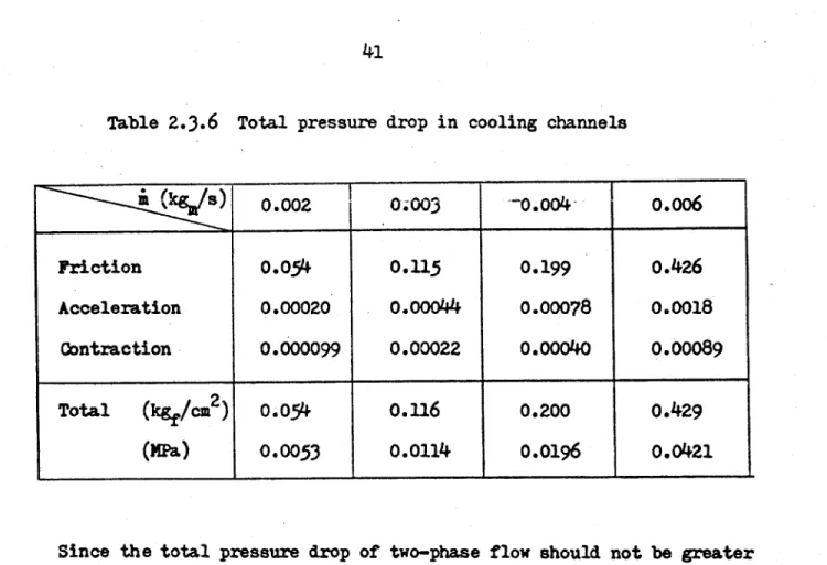
Table 2.3.6 Total pressure drop in cooling channels
0.002
00003
-0.004-
o.o6
Friction
0.054
0.115
0.199
0.426
Acceleration
0.00020
0.00044
0.00078
0.0018
Contraction
0.000099
0.00022
0.00040
0.00089
Total
(kgf/cm
2)
0.054
0.116
0.200
0.429
(HPa)
0.0053
0.0114
0.0196
0.0421
Since the total pressure drop of two-phase flow should not be greater than 0.02 MPa as shown in Table 2.3.4, the maximum flow rate of each channel is about 0.004 kgm/sec.
The maximum length Lc of superconductor whose state-transition does not propagate to the rest of the magnet is given by
i Ah
L c 7r. D (' (2.3.21)
c
where
Ah = maximum difference between inlet enthalpy and outlet enthalpy S17300 -
11200
= 6100 J/kgWhen
A
= 0.0036 kg/sec is chosen,0.0036 kg/sec- 6100 J/kg
O
0.008 a - 0.
2x
le W/m
-0.437
m
The corresponding heat tranfer coefficient hCal is calculated as followss
From Equations (2.3.7)
-(2.3.10) we obtain
h
ho2 + h
hb
=0.82 W/cm
2K
and we can use the following correlations
0.8
0.4
(2.3.o.)
Is~
0.023 (Ref)
(Prf)
(--2
where
kf
=thermal conductivity of liquid helium
0.028 W/.-K
Prf
Prandtl number for liquid helium
a CpO.f/kf
5.88
x103J/kg-K - 3.6 X10⁻⁶ N-sec/n
20.756
0.028 W/m.K
Ref
ff
Vf
D/
/-f
d122 kg/m
3- 0.701
n/sec
- 0.008
m
1.90X 10⁵
3.6x
10N.sec/m
Then
ho
0.028 0.023 (1.90X
105)0.8
(0-756)0.4
0.008
1203 W/m2.
K=
0.12 W/cm2.
KHence we obtain
h al :0.822
0.122
=
0.83 W/cm. K
As expected earlier, the contribution of forced convection heat tranfer
is small compared with that of nucleate boiling heat transfer.
2.4 Magnet Joints
The superconducting magnet windings are composed of sixty segments
and, consequently there are sixty magnet joints which connect the segments
in series.
Main design requirements which the magnet joints should satisfy
are as follows:
1) Electrical resistance should be small enough.
2) Ohmic heat generated in the joints should be removed efficiently.
3)
Sliding movement of the magnet windings caused by thermal contraction
should be accommodated in the joints.
4) Maintainability should be considered to make it practical to assemble
and disassemble the magnet windings.
a. Pressure Contacts
In order to achieve low electrical resistance of the demountable
magnet joints, pressure contacts will be applied.
Figure 2.4.1 and
Figure 2.4.2 show the end part of a
magnet segment.
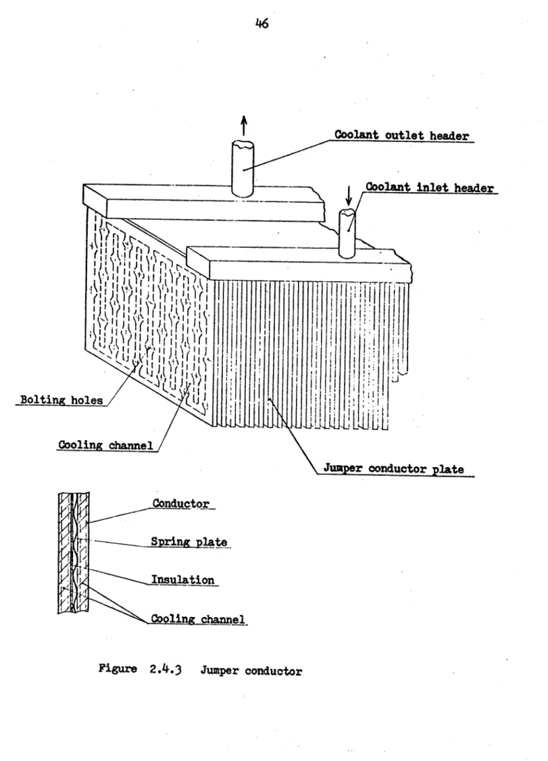
Figure 2.4.3 shows
a jumper conductor, which consists of about thirty-seven plates and is
installed. in a gap space between adjacent magnet segments.
Contact surface area of each joint Sc is
Sc = 40 x 80
=
3200 cm2
And
the total number of the contact surfaces for a whole reactor N c is
Nc
= 2 x 73 60 = 9000
44
Coil case cooling duct.
Conductor cooling duct
Collecting header of
conductor coolanttill
I ICollecting header of
coil-case coolant
Figure 2.4.1
Structure of the end part of magnet segment
:1:
-.I
iiI
II
~2
ii-*-4~
I N N N NI-
t
Figure 2.4.2
Structure of the end part of conductor plates
Coolant inlet (or outlet)
46
Coolant outlet header
-
Coolant inlet header
Bolti
holes
[t
Cooling channel
Jun r conductor plate
Conductor
-
Spring
plate
*Insulation_
Cooling channel
Wr = 1/CI p2 f N c/( tc0 s)
= 300
(5
x105 Amp.)2 fe
(9000/3200-1c)
(2.4.1)
= 2.lx
0
0
1f
where
Cr
=coefficient of performance of the refrigeration system
I
=
current in each conductor plate
p
L=
ratio of effective contact area to total surface area
Using Equation (2.4.1) the required refrigeration power Wr is plotted
as a
function of
f
and f in Figure 2.4.4.
When the effective contact area
is assumed to be 50 %
(
Ic
= 0.5) and
Wc
should be less than 15 MWe (1 % of
plant power output)
Ic < 3.5X10
8ohm.C2
2(2.4.2)
In this study
.
= 1 X 10
ohm cm
2and, as a result, Wr
=4.23 MWe
a
assumed.
Contact resistivity depends upon the magnitude of contact
pressure and surface type.
Among several clamping methods, such as hydraulic clamping, various
mechanical clamping, thermal clamping using a defference of thermal
contraction, bolting will be most applicable under severe restrictions on an
available space and maintenance procedures.
Since contact resistivity decreases with increasing contact pressure,
bolting is required to be tough enough.
Considering limitations of the
number and size of the bolts and strength of bolt materials, obtainable
contact pressure will be up to 15 MPa (2100 psi). For example, when
thirty-[18]
48
100
50
0)
1010
43 .4 5 IL5-gxr9
2x.4.
Figure 2.4.45X10-8
1-10~7
Contact resistivity (ohm cm
)
5xl -7
Refrigeration power required to cool magnet joints
=
0.25
0.5
=
0.75
effective contact area
c
total surface area
each jumber conductor, maximum contact pressure is about 10 MPa (1500 psi).
However, as described later, the clamping pressure is restricted to about
4 MPa (600 psi) by an additional requirement so as to allow sliding movement
of conductor plates caused by thermal contraction.
[17:]