Design, Build, and Characterization of a Platform for Testing Bio-Inspired, Pressure-Compensating Valves
by Anne Warren
Submitted to the
Department of Mechanical Engineering
in Partial Fulfillment of the Requirements for the Degree of
Bachelor of Science in Mechanical Engineering
at the
Massachusetts Institute of Technology
June 2013
ARCHIVES
MAASSACHUSETTS INSTITUTE OF TECH NOLOC.YJUL 3 2013
1L S7F\AR IE S
@ 2013 Massachusetts Institute of Technology. All rights reserved.
Signature of Author:
Department of Mechanical Engineering May 8, 2013
Certified by:
A s G. Winter V
Noyce Career Developme 'stant Professor Thesis Supervisor
Accepted by:
Anette Hosoi Professor of Mechanical Engineering Undergraduate Officer
Design, Build, and Characterization of a Platform for Testing Bio-Inspired, Pressure-Compensating Valves
by Anne Warren
Submitted to the Department of Mechanical Engineering on May 8, 2013 in Partial Fulfillment of the
Requirements for the Degree of
Bachelor of Science in Mechanical Engineering
ABSTRACT
I design and build a testing platform to further the study and testing of bio-inspired, compensating valves. Research into an inexpensive design for a pressure-compensating valve designed to address the low-cost, high water efficiency needs of subsistence farmers in developing countries has already begun through proof-of-concept prototypes and testing; This project builds on the early-stage testing. A stable test set-up, designed for easy use and repeatability was needed in order to perform tests on valve prototypes with more accuracy and precision. I took into
consideration the structural and systems needs of the test set-up, and proceeded to build and run tests on various tubing prototypes. By comparing these test results with previous proof-of-concept tests and analytical models, I show that this test set-up can provide meaningful data for the testing of pressure-compensating valves, and could be used for future investigation into the design of such valves to be used in drip irrigation systems in developing countries.
Thesis Supervisor: Amos G. Winter V
TABLE OF CONTENTS ABSTRACT 3 TABLE OF CONTENTS 4 LIST OF FIGURES 5 INTRODUCTION 6 BIO-INSPIRED PRESSURE-COMPENSATION 7
Pressure Compensation Through Variable Flow Area 7
TESTING SET-UP 8
Design Process and Documentation 8
System Characterization and Calibration 13
PROTOTYPE TESTING 16
Prototype Selection 16
Prototype Performance 17
CONCLUSIONS 24
LIST OF FIGURES
Figure 1a: Early-stage, "tank based" testing set-up design 9
Figure 1b: Early-stage clamped tubing testing set-up design 9
Figure 1c: Early-stage "sourced parts" testing set-up design 10
Figure 2: Photograph of final tank set-up 11
Figure 3: Early schematic of full system design 12
Figure 4: Photograph of final full-system set-up 13
Figure 5a: Graph correlating arbitrary scale on large flow meter with system flow
rate 14
Figure 5b: Graph correlating arbitrary scale on small flow meter with system flow
rate 14
Figure 6: Photograph of pump used in the overall testing platform 15
Figure 7: Graph of pump characterization data 16
Figure 8a: Photograph of the valve prototype made from Jain tubing 17 Figure 8b: Photograph of valve prototype made from 2.5" Microspec tubing 17 Figure 9: Graph relating flow rate and pressure for 5" Jain tube 18 Figure 10a: Photograph of Jain tubing partially clamped shut 19
Figure 10b: Photograph of Jain tubing fully clamped shut 19
Figure 11a: Graph relating flow rate and pressure for 3.75" Microspec tube 20 Figure 11b: Graph relating flow rate and pressure for 2.5" Microspec tube 20 Figure 11c: Graph relating flow rate and pressure for 1.25" Microspec tube 21
Figure 12: Graph superimposing the average relationship between flow rate and pressure for all three Microspec tubes
Figure 13a: Photograph of Microspec tube, fully open 22
Figure 13b: Photograph of Microspec tube, partially clamped shut 22 Figure 13c: Photograph of Microspec tube, fully clamped shut 23 Figure 14: Graph superimposing the average relationship between flow rate and
INTRODUCTION
This paper explores cost effective options for regulating flow in drip irrigation systems in developing countries. It focuses on the design process and building of a testing rig, which was then used for proof-of-concept testing of bio-inspired, pressure-compensating valves, as well as for more consistent and accurate testing of a selection of valve prototypes.
Drip irrigation is a well-established method of water delivery in agriculture; water is pumped through tubes to 'emitters', valves that regulate the flow and deliver water straight to the plants' roots [1]. The more traditional method of flood irrigation involves flooding fields with water, most of which evaporates or is
absorbed by the ground. As water populations increase and water becomes scarce, interest in drip irrigation as an alternative to the much more wasteful methods of flood irrigation, has grown [1]. The major factor limiting a more widespread adoption of drip irrigation in developing countries such as India is cost. Drip irrigation requires a large network of tubes, thousands of emitters per acre, and a pump and power source, all of which contribute to high costs. In order for a drip
irrigation system for a 1-acre field to be affordable for subsistence farmers in India, it must only cost $300 in total [2]. Currently, drip irrigation systems cost thousands of dollars.
An immediate and sustainable reduction in cost can be made by decreasing the necessary pumping pressure of the water, the most important factor in the power consumption and price of the pump [2]. However, running these systems at low pressures in the range of 0.1 - 0.3 bar requires special pressure-compensating emitters, in order to respond to the non-uniform pressure distributions caused by viscous losses and elevation changes in the system.
Pressure compensation is the ability of a valve to regulate output and
produce a constant flow rate regardless of the pressure difference across the valve. The pressure-compensating valve begins to collapse at a threshold pressure, called
activation pressure, or APactivation, which results in a reduction of the valve's inlet
area, effectively regulating and maintaining the output flow rate. Pressure
compensating emitters for use in irrigation are already available, however due to design, material choice, and production costs, these emitters don't meet the
requirements for low pressure, low-cost irrigation; they activate at APgreater than 0.6 bar, and they cost roughly double the maximum allowable amount needed to meet the $300 total-system cost threshold [2].
There is a need for low cost, pressure-compensating emitters that are activated at pressures between 0.1 -0.3 bar (5 times lower than the APactivation of
current emitters). A low 6Pactivation would allow the drip irrigation system to operate effectively at low pressures, thereby reducing power consumption. In addition, these emitters must enable flow in the range of 3 - 20 liters per hour, depending on the crop and soil type. Other important factors include robustness for handling in the field, as well as large flow channels to prevent clogging. Preliminary and proof-of-concept tests have been done on a pressure-compensating valve inspired by mechanisms in the human airway and blood vessels [2].
While work has been done to design and test bio-inspired pressure-compensating valves, there was a distinct need to expand and improve testing conditions, a need to design and build a platform for more accurately testing these prototypes. The goal of this project was to build a test set-up that was permanent and hardy in order to minimize discrepancies in data collection over time. It was
also important that the design be modular, to accommodate frequent and quick changing of the test objects, as well as to allow for measurements to be taken over a wide range of flow rates and pressures. Building a testing rig was a necessary next step in this research into low-cost, self-regulating valves.
This paper seeks to build on the previously conducted research and tests conducted by Pawel Zimoch and Eliott Tixier in "Bio-Inspired, Low-Cost, Self-Regulating Valves for Drip Irrigation in Developing Countries". After an overview of the analytical model of bio-inspired pressure compensation, I describe the design and building of a permanent test rig that was and can continue to be used to more accurately test the pressure-compensating qualities of different valve prototypes, as well as begin to explore the influence of the design parameters of length, material, and diameter on the APactivation and the output flow rates of these prototypes. The structural simplicity of these bio-inspired flow regulators would allow for savings on manufacturing costs. The combination of this factor with a design that decreases water and electricity usage would significantly reduce the costs associated with the manufacture and use of drip irrigation systems, and would make drip irrigation a financially viable technology for developing countries.
BIO-INSPIRED PRESSURE-COMPENSATION
Inspiration for the design of the pressure-compensating valve modeled and designed by Tixier and Zimoch [2], was drawn from the human body, where flow has to be regulated carefully, by a variety of different methods. One such method can be modeled as a variable area valve applied to explain pressure compensation in thin-walled structures, and is exemplified by the human airway; this method was first modeled analytically by Asher Shapiro [3], and forms the basis for the work in the following section.
Pressure Compensation Through Variable Flow Area
As an incompressible fluid passes through a pressure-reducing valve, the fluid's pressure decreases due to viscous losses in the valve. This change in
pressure, AP can be expressed in terms of the density of the fluid p, the velocity of the fluid u, and dimensionless parameter Kf, which can be treated as a constant [3]. This equation for AP is
AP = Kf pU2 (1)
The velocity of the fluid inside a pressure-reducing valve is typically not constant, so the velocity u must be chosen with respect to a reference area A. A tube with a variable flow area is a good model for a pressure-compensating valve, and by
looking at a basic, straight tube with variable flow area we can adapt (1) to
represent this model. The pressure drop expressed as a function of the flow rate
Q
is AP = Kf p (Q/A)2(2) The reference area A is the cross-sectional area of the tube, and Kf for this geometry
is Kf = f (L/D) where L is the length of the tube, D is its hydraulic diameter and f is
the Moody friction factor [3]. Based on this model, in order to achieve pressure compensation, AP ~ A2, which shows that there is a non-linear dependence of the
tube's area A on the pressure difference across the valve. Consequently, in order to achieve pressure-compensation in a model involving a straight tube, a degree of nonlinearity must be present, which can be provided by the deformation of flexible tubing, causing the flow area to vary.
TESTING SET-UP
In order to perform repeatable and rigorous tests on various tubing prototypes, I designed and built a testing setup specifically designed for easy interchanging of prototypes, visibility, and durability. These were three major design requirements of the system, beyond the basic necessity of accurate and precise measurement. It was important for the test set up to include an element of modularity. The testing set-up needed to accommodate for a wide range of valve prototypes, and in order to streamline the testing processes, also needed to allow for quick changing and easy access to the prototypes. Visibility was a key
consideration, as variable-area pressure-compensation has a distinct visual result; It is important to be able to see and document the changes in the tubes as the pressure changes. Durability and general hardiness were important aspects of my design, both to allow for accuracy and precision in my own testing, but also to increase the longevity of the set-up and allow for future testing. The design stages and
documentation, and calibration and characterization procedures and results, are detailed in the following sections.
Design Process and Documentation
I began the process of designing a test setup by brainstorming various
assemblies that allowed for easy changing of prototypes. Some initial ideas included a clear aquarium-like tank with a removable lid, a clear, compliant tube with
clamped ends similar to the one used by Tixier and Zimoch [2], and for an inexpensive "found materials" approach, a modified 2 liter soda bottle. Initial sketches for these ideas can be seen in figures la-c, respectively.
Figure la. Possible design for a testing 'tank' with a removable lid for easy access to tube prototypes clear tubing inlet tube outlet tube hose clamps
Figure 1b. Possible design for test setup, inspired by concept and prototype testing done
in "Bio-Inspired, Low-Cost, Self-Regulating Valves for Drip Irrigation in Developing Countries"
watertight container with removable lid
outlet
inlet tube
soda bottle
inlet tube outlet
Figure 1c. Possible design for test setup, design focused on 'sourced' inexpensive materials, as well as a removable cap for easy changing of tube prototypes
Ultimately, after further iteration and research into available materials, I settled on a design that used clear cylindrical tubing with one end sealed and
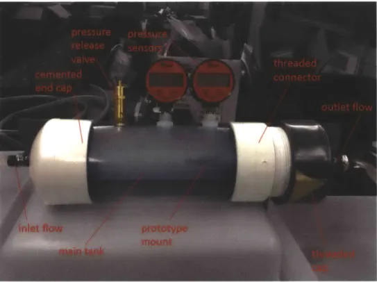
cemented shut with a cap, and one end fitted for a threaded end-cap. Through quick analytical analysis, it was easy to determine that a cylindrical vessel was better suited for pressurizing, as the stresses are more evenly distributed around the vessel, rather than a rectangular vessel, where the stresses tend to occur at the joints. The hoop stress of a cylinder, ch = pd/2t, where p is the internal pressure of the cylinder, d is the diameter, and t is the wall thickness. The combined max tensile stress of a rectangular pressure vessel is a = 6ap(L/t)2 + pL/2t where L is the length of the cross-section, h is the height of the cross-section, a is a parameter dependent on h/L, p is the internal pressure of the vessel, and t is the wall thickness [4]. A comparison equivalently sized cylindrical and rectangular vessels indicates that rectangular vessels are much less efficient; cylindrical vessels will sustain much higher pressures, hence why I chose a cylindrical tube to become the main testing tank for my final design. The threaded end-cap allows for easy changing of tube prototypes. The threaded end-cap is fitted with a through-wall, threaded connector, which provides a mount for the prototype tubes inside of the tank, as well as a coupler for the output tube. The individual parts of the main water tank are shown and labeled in Figure 2, below. The pipe selected to become the main water tank was a schedule 40 clear PVC pipe, with a maximum allowable internal pressure of
Figure 2: Final testing tank
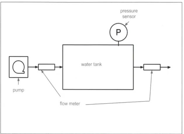
Also taken into consideration was the design of the overall system, in order to best facilitate testing. A simple, early systems model involving a pump, a flow meter, a main water tank with embedded pressure sensor, and another flow meter, all in series, can be seen below in Figure 3. This straightforward design took in to consideration the ability to measure inlet and outlet flow rate, as well as a pressure sensor placed closely to the valve prototype. The decision to place the pressure sensor close to the valve prototype location was important because the goal of the system is to measure the pressure drop across the valve. By locating the sensor as close to the valve as possible, I am making the assumption that it measures this pressure drop.
pressure sensor
P
water tank pump flow meterFigure 3: Early schematic showing a potential total system design for the test set-up
The end result varied very little from this basic, early model. The final set-up is comprised of a multi-speed gear pump, two flow-meters installed in parallel (with ball-valves controlling the flow into each meter), the main water tank with two mounted digital pressure sensors, and a ball valve at the outlet of the system. A pressure release valve was added to the tank, to prevent the system from exceeding internal pressures of 25 psi. Two pressure gauges were used instead of one, to provide a larger range of measurement. The first pressure sensor measured
pressure within the range of 0 - 15 psi, and the second measured the range from 0
-30 psi. These pressure gauges were chosen because together they cover 0 - 2 bar pressure range, easily exceeding the goal pressure range of 0.1-0.3 bar, but also providing room to measure higher pressures that could occur with different prototypes. The flow meter at the output of the tank was omitted from the final design, and a ball valve was installed instead. I deemed that, because the inlet and outlet tubes were of the same diameter, the difference in the inlet and outlet flow was negligible, and flow meters placed at the inlet were sufficient for measuring flow rate through the system. Two flow meters were installed in parallel, and
measured different ranges of flow, allowing for flexibility between tests. A ball valve was connected to the outlet tubing in order to allow for ease of use, in order to run pump calibration tests, and to prevent water spillage between tests. During the
system setup can be seen in its entirety in Figure 4. All of these design choices, some made before building the set-up, and some decided upon after running the system and debugging problems that arose, were made in order to provide a consistent and accurate testing platform for different valve prototypes. Overall the design also focused on modularity and ease of use.
Figure 4: Full system set-up System characterization and calibration
After the initial design and building stages, multiple tests were run on the system first to test the efficacy of all of the individual parts, and then to characterize the pump and calibrate the flow meters. Both flow meters are marked with
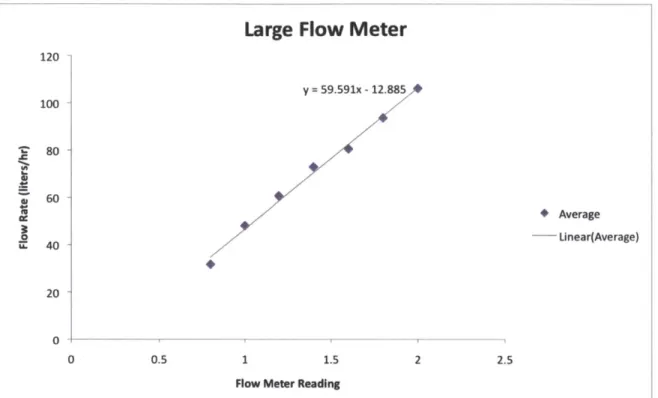
arbitrary scales that needed to be related to the flow rate through the system. The smaller flow meter has a display range from 10 - 100, in increments of 5, the larger flow meter ranges from .8 - 6.0, in increments of .2. In order to calibrate these flow meters to liters/hr, I ran multiple tests measuring the time it took fill a 0.5-liter vessel, at various values on the flow meters. The results of these calibrations for the large and small flow meters, respectively, can be seen in Figures 5a-b. As can be seen from the graphs in Figures 5a-b, both flow meters demonstrated a linear relationship between the reading on the meter and the physical flow rate that resulted. This data was then interpolated to relate to the entire range of values displayed by each flow meter. Based on this interpolation, the large flow meter registers flows in the range of 35 - 357 liters/hr, and the small flow meter records
Large Flow Meter
120 -100 . 80 - 60-40 -y = 59.591x - 12.885 * Average Linear(Average) 20 0 0 0.5 1 1.5 2 2.5Flow Meter Reading
Figure 5a: This graph shows the correlation between the scale on the large flow meter and the flow rate through the system. The linear equation y = 59.591x - 12.885 was fit
to this data, and was used to interpolate the flow rates across the flow meter's full measurement range. The results were used for all subsequent testing and data
gathering.
Small Flow Meter
U. 60 50 40 30 20 * Average Linear(Average) 10 20 30 40
Flow Meter Reading
50 60 70
10
0 0
Figure 5b: This graph shows the correlation between the scale on the small flow meter and the flow rate through the system. The linear equation y = 0.8754x + 3.9347 was fit to this data, and was used to interpolate the flow rates across the meter's full range
The procedure for characterizing the pump involved first closing the output valve and switching on the pump to a predetermined pump speed (as indicated by the dial on the front of the pump). After allowing the pressure inside the tank to reach 20 psi, the outlet valve was gradually opened in stages, allowing the system to reach a steady state before a measurement of pressure and flow rate was recorded at each stage. A test was run for each of the two lowest pump speeds, 1 and 2, as indicated on the dial of the pump, which is shown in Figure 6. Calibration testing was performed on only the lowest two pump speeds because the associated flow rates produced covered the entire testing range, reaching 90 liters/hr (with pump speed 2). Pump speeds 3 and above produced flow rates that were much higher than the target range of 3 - 20 liters/hr. The results of the pump calibration tests are shown in Figure 7. Testing was important to determine the characteristic relationship between the pressures and flow rate for this specific pump, in order to confirm that it will simultaneously meet the required pressures and flow rates. Pump speed 1 produced pressures from 0.1 - 0.3 bar associated with flow rates from approximately 40 - 45 liters/hr, which is close to the testing range of 3 - 20 liters/hr. Ideally I would select a pump that is optimized for these goal pressures and flow ranges, but this pump was close enough to the ideal range to perform tests on the system and prototype valves. It was also chosen because it was simple to use, and would be easy to change out, if necessary in the future.
Pump Characterization
1.6 1.4 1.2 11 0.8 A A Pump Speed 1 0.6 A *Pump Speed 2 0.4 0.2 A 0 - - T 0.00 10.00 20.00 30.00 40.00 50.00 60.00 70.00 80.00 90.00 100.00 Flow Rate (liters/hr)Figure 7: This graph shows pump performance curves for the two lowest speed settings of the pump used in this setup. Both speeds demonstrate a negative linear relationship
between Flow Rate and Pressure.
PROTOTYPE TESTING
After fully establishing and characterizing the testing setup, I used this platform to perform further proof-of-concept tests on a variety of tubing samples. I also preformed tests to determine the relationship between a tubing prototype's lengths on its pressure-compensating qualities. The main goal of these test were to further test the system's design itself, to determine that it was effective for testing bio-inspired, pressure-compensating valves.
Prototype Selection
In the interest of simplicity, I sourced ready-made tubing samples for use as prototypes from medical tubing suppliers and from Jain Irrigation Inc. Prototypes were selected from a variety of tubing options, based on their elasticity and wall thickness. The two tubing samples I selected for testing were LDPE tubing
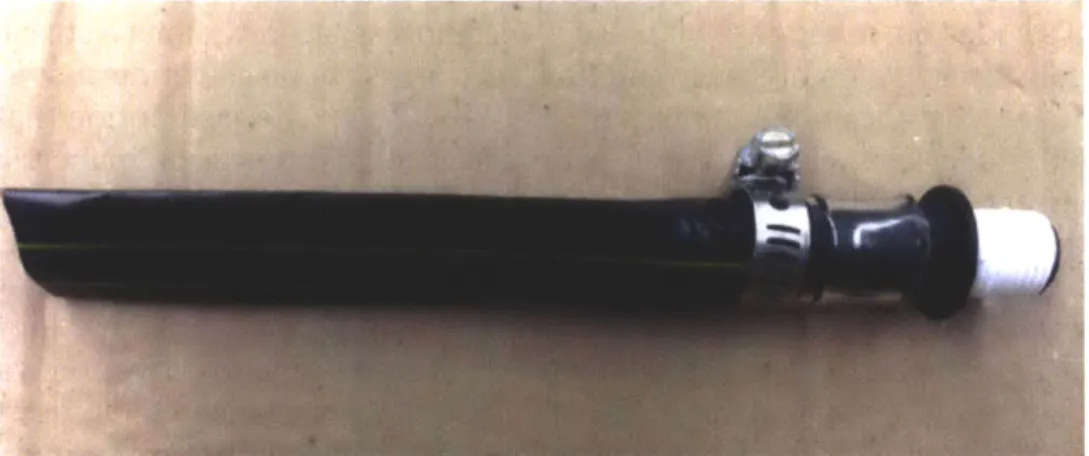
produced by Jain, and a tubing sample produced by Microspec, a medical extrusion company. The Microspec tube is produced from the registered trademark material Pellethane®, a medical grade thermoplastic polyurethane. The Jain tube prototype is shown below in Figure 8a, and the Microspec prototype is shown in Figure 8b. The Jain tube I used for testing measured 5 inches in length, had an outer diameter of 0.65 in, and wall thickness of 0.0075 inches. I ran tests on three lengths of Microspec tubing, measuring 3.75 in, 2.5 in, and 1.25 inches long, respectively. All
three samples had an outer diameter of 0.253 inches, and a wall thickness of 0.005 inches.
Figure 8a: Valve prototype made from tubing supplied by Jain Inc. Length = 5 inches, outer diameter = 0.65 inches, and thickness = 0.0075 inches
Figure 8b: Microspec tubing used as a valve prototype. Medium length piece shown, with length = 2.5 inches, outer diameter = 0.253 inches, and thickness = 0.005 inches
Prototype Performance
To measure the performance of the prototypes, I mounted the valve
prototypes inside the water tank, and proceeded to begin filling the tank with water. I allowed the prototype and outlet tube to fill completely with water (eliminating air bubbles) before closing the output valve and filling the rest of the tank with water. Once full, the pressure release valve on the tank was closed, and the outlet valve re-opened. I then began testing the prototype valves, increasing the power output of the pump in stages; as the power varied, both the flow rate through and the
pressure across the valve varied. I recorded data points for flow rate and pressure at each stage, making sure to allow the flow to reach steady state before each measurement. Each prototype eventually reached its APactivation, where it would collapse in on itself, preventing flow. At this point the pressure inside the test chamber would build quickly, as flow dropped to a trickle. I measured and recorded flow rate and corresponding pressure until the system reached steady state or exceeded the pressure release valve's maximum pressure of 25 psi.
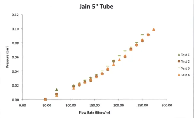
The 5 inch long Jain tubing prototype was tested four times, using the larger flow meter (34-357 l/hr), with the graphical results shown in Figure 9. These results show a quadratic relationship, which is consistent with a theoretical analysis. From Bernoulli's equation, in the case of inviscid, incompressible flow along a streamline, the relationship between pressure and flow (in the case of no elevation changes) at two points on this streamline can be simplified to AP - v2. The assumption that the flow is inviscid is valid where viscous forces are small in comparison to inertial forces, and are associated with flow situations where the Reynolds number is much
greater than one. The quadratic relationship zIP - v2 is reflected in the results
shown in Figure 9. As the pressure in the tank approached 0.1 bar, the valve almost instantly clamped shut, crumpling in on itself, showing APactivation = 0.1 bar for this particular prototype. The corresponding flow rate at the time of activation was approximately 270 liters/hour, an order of magnitude greater than the required
flow rate. The crumpling response was documented, and Figure 10a-b shows pictures of the progression to a fully closed valve. In the case of the Jain tubing, as the valve shut the pressure built up inside the tank, reaching the pressure release valve's threshold of 25 psi (1.72 bar) within seconds, activating the pressure
release, and making it nearly impossible to record measurements for the post-clamping phase. The images shown in Figures 10a-b were taken in very quick succession.
Jain
5" Tube
0.12 0.10 A 0.08 -0.06 A Test 2 A *Test 2 0. -Test3 O.O~j11ATest4
0.022ATs
0.00 0.00 50.00 100.00 150.00 200.00 250.00 300.00 Flow Rate (liters/hr)Figure 9: This chart demonstrates the relationship dP - v2 between increasing pressure and the resulting flow rate through the system, due to Bernoulli's equation for inviscid,
Figure 10a: Tube on the verge of clamping shut
Figure 10b: Tube is fully shut, restricting flow
I also ran tests on samples of Microspec tubing measuring 3.75 in, 2.5 in, and 1.25 inches in length. For these samples, I used the small flow meter, which
measures a range of about 12.7 - 91.9 liters/hr. The test procedure remained the same as in the Jain prototype testing case. Results from the long, medium, and short Microspec samples can be seen in Figures 11a-c, respectively, and superimposed onto one chart in Figure 12. Similarly to the Jain case, all three Microspec tubes crimped shut when the external pressure reached a specific APactivation. The longest,
3.75 in tube showed a.APactivation of approximately 0.48-0.58 psi (0.03-0.04 bar). The flow rate at the instance of clamping was 70 liters/hour. Images sequencing this action are shown in Figures 13a-c. I found that in the case of the medium, 2.5 in. long tube, that it clamped shut at a similar APactivation, in the range of 0.48-0.58 psi, as the longer tube, but at higher flow rates, on the order of 78 liters/hr. The shortest tubing segment, 1.25 inches in length, demonstrated a APactivation around 0.3 psi (.02 bar), at a flow rate of 70 liters/hr.
Microspec 3.75" Tube
1.40 -1.20 -1.00 -0.80 -0.60 0.40 0.20 0.00 0.00 10.00 20.00 0 m m m a am 11 30.00 40.00 50.00 Flow Rate (lIters/hr)60.00 70.00 80.00
Figure 11a: Relationship between pressure and flow rate through 3.75 in. long Microspec tube
Microspec 2.5" Tube
1.60 1.40 1.20 1.00 0.80 E 1 0.60 0.40 0.20 11 S Trial 1 X Trial 2 .Trial 3 0.00 -- -- --- U---- -1 U - I 0.00 10.00 20.00 30.00 40.00 50.00 60.00 70.00 80.00 90.00 Flow Rate (llters/hr)Figure 11b: Relationship between pressure and flow rate through 2.5 in. long Microspec tube I ETrial 1 X Trial 2 *Trial 3 CL
Microspec 1.25" Tube
1.60 1.40 1.20 1.00 0.80 0.60 0.40 0.20 M x U x 0.00 0.00 10.00 20.00 30.00 40.00 50.00 60.00 70.00Flow Rate (lIters/hr)
Figure 11c: Relationship between pressure and flow rate acting on Microspec tube
1.25 in. long
Microspec tubes, all 3 lengths
-+-2.5" Tube -*-3.75" Tube
*-1.25" Tube
10.00 20.00 30.00 40.00 50.00 60.00 70.00 80.00 90.00
Flow Rate (liters/hr)
Figure 12: Average results from each of the three lengths of valve prototypes, superimposed onto one graph. The red represents the longest, 3.75" prototype, the
blue represents the 2.5" tube, and the green the 1.25" valve U .0 S ETrial 1 X Trial 2 *Trial 3 80.00 1.60 -1.40 1.20 1.00 0.80 0.60
&
0.40 0.20 0.00 4-0.00Figure 13a: Fully open stage, APactivation not yet reached
Figure 13c: Fully closed valve
Looking at the results from the four prototypes, it is clear that length, diameter, and material composition all play an important part in the pressure compensation qualities of these valve prototypes. Comparing the Jain tubing prototype with group of Microspec tubing prototypes, as can be seen graphically in Figure 14, there are clearly differences in test results due to features such as valve diameter, material composition, and length, as the Jain tube allowed for flow rates an order of magnitude higher than those produced by the Microspec tubes. Looking at the three lengths of Microspec tubing, the 3.75 inch and 2.5 inch tubes both had APactivation of approximately 0.5 psi (0.04 bar), but that the clamping occurred at a
slightly higher flow rate for the shorter tube. The shortest tube had a APactivation of
All Prototypes
1.6 1 1.4 -4A 1.2 0.8 "'-"-Jain 5" Tube +"-2.5" Tube 0.6 -U---3.75" Tube -- 1.25" Tube 0.4 0.2 0 0.00 50.00 100.00 150.00 200.00 250.00 300.00Flow Rate (Ilters/hr)
Figure 14: Data for all valve prototypes, averaged and superimposed onto one graph. The differences in flow rate and pressure at the time of activation are clearly visible. The purple data points represent the Jain tube, while the red, blue, and green data
points represent the long, medium, and short Microspec tubes, respectively
These experiments were most importantly a way of testing the system design and its ability to run tests on valve prototypes. The final set-up, as described earlier in the paper, was able to take all of the measurements necessary for effective
characterization of tubing prototypes, namely the flow rate through the system and the pressure drop across the valve, for a variety of different prototypes with
different size and material composition. Visual observations and documentation were easy to make due to the choice of clear PVC for the water tank body. The two flow meters were easily interchangeable, and allowed for testing prototypes that performed differently under different flow rates, such as the Jain and Microspec tubing. Overall, the results of these tests are consistent with the analytical findings and results from proof-of-concept tests done by Tixier and Zimoch [2], and further demonstrate the ease-of-use, as well as accuracy and precision of the testing system built for this project.
CONCLUSIONS
This project further validates the possibility of using bio-inspired, thin-walled tubing to create pressure-compensating valves to be used in drip irrigation systems in developing countries. The Microspec tubing prototypes that were tested demonstrated values Of dPactivatin come within close reach of the 0.1-0.3 bar range
end of this range, with a APactivation of 0.1 bar, but far overreaches the optimal flow range of 3-20 1/hour; At 270 liters/hour, it is about an order of magnitude off. Through further research into factors such as compliance of the valves as well as cross-sectional shapes and areas, it is reasonable to believe that an optimized valve could be produced, meeting both the APactivation requirements of 0.1-0.3 bar, and the flow requirements of 3-20 liters/hour. The testing set-up built as a part of this project will also serve as a key part of further testing, continuing to allow for testing and development of the project as a whole.
REFERENCES
[1] Government of India, M. o. A., 2004. Salient Findings and Recommendations of Task Force on Microirrigation
[2] Tixier, Eliott, and Pawel Zimoch, 2013. "Bio-Inspired, Low-Cost, Self-Regulating Valves for Drip Irrigation in Developing Countries". ASME paper no.
DETC2013-12495
[3] Shapiro, A. H., 1977. "Steady Flow in Collapsible Tubes".Journal of Biomechanical
Engineering, 99 p. 126.
[4] Starczewski, M., 1981. "Non-Circular Pressure Vessels- Some guidance notes for designers". British Engine Technical Report, 14 pg. 62.