Distributed Software Design for Collaborative
Learning System Over the Internet
by
Christine Hui Su
Submitted to the Department of Electrical Engineering and
Computer Science
in partial fulfillment of the requirements for the degrees of
Master of Engineering in Electrical Engineering and Computer
Science and Bachelor of Science in Electrical Engineering
at the
MASSACHUSETTS INSTITUTE OF TECHNOLOGY
May 1998
C
-
.
@
Christine Hui Su, MCMXCVIII. All rights reserved.
The author hereby grants to MIT permission to reproduce and
distribute publicly paper and electronic copies of this thesis
document in whole or in part, and to grant others the right to do so.
A uthor
...
Departnient of Electrical Enginering and Computer Science
1
lMav
22,
1998
Certified by ...
Fen'iosky Pefia-Mora
Assistant Professor
r h is
Su-pervisor
Eng
Accepted
by ...
ItmULep .C i 11otChairman, Department Committee on Graduate Theses
MASSACHUSETTS INSTITUTEOF TECHNOLOGY
JUL 14 1998
LIBRARIES
Distributed Software Design for Collaborative Learning
System Over the Internet
by
Christine Hui Su
Submitted to the Department of Electrical Engineering and Computer Science on May 22, 1998, in partial fulfillment of the
requirements for the degrees of
Master of Engineering in Electrical Engineering and Computer Science and Bachelor of Science in Electrical Engineering
Abstract
In this thesis, a software design approach is introduced to solve the distance collabo-rative learning system problem. As Internet usage becomes popular, people from all disciplines seek to utilize the net as both a communication and learning tool to de-velop projects and improve work efficiencies. However, there are limited collaborative tools available in the market, and the research in distance communication has not tackle the problem of providing casual contact along with social interaction features. This thesis presents an applicable object-oriented design for distance collaborative system using Unified Modeling Language notations. In addition, the benefits and pitfalls in working with a diversified and geographically separated team is shared in this thesis.
Thesis Supervisor: Feniosky Pefia-Mora Title: Assistant Professor
Acknowledgments
First of all, I would like to thank Professor Pefia-Mora for introducing me to this interesting project and giving me insightful guidance through out the thesis phase. I would also like to extend my appreciation to my CICESE and MIT instructors and team members, Jesus Favela, Josephina Rodriguez, Bob Yang, Felix Loera, Simonetta Rodriguez, Humberto Chavez, Rene Navarro, Sergio Infante, Kareem Benjamin, Juan Contreras, Gregorio Cruz, Lidia Gomez, Diana Ruiz, Charles Nijendu, Juan Fancisco, and Marcela Rodriguez. Without them, the project would not be completed. In addition, I would like to acknowledge the teach assistants, Karim Hussein and Siva Dirisala, who had spent time in setting up equipment and videotyping our progress.
In my five years at MIT, I also had gotten to know a few people who had became good friends of mine. I would like to thank them for being with me through the good and bad times, tolerated my bad behaviors, listened to my complaints and shared my happiness. Countless thanks to Cindy, who had made my MIT life a lot more interesting; to Sanjeev, who has been more than a great boss; to Inn, who is a God sent angel and, who introduced me to Christianity; to Henry, who I have gotten to know better lately, it was wonderful to have him as a friend; to Marcus, who had taught me so much about life outside of MIT; and to Bob, who is talented and wonderful to work with.
Least not the less, I would like to thank my parents and my sister. My mom is the most incredible person I have known, and she continues to be my best friend throughout the past five years. I just cannot say enough thanks to express my grati-tude towards her. I also want to thank my little sister, who is intelligent, energetic, responsible, and creative. Finally, I would like to extend my appreciation to Jinzy Zhu, Patrick Yeung, Yoko Kusumoto, Sunnia Lin, and Jay Ongg. They had been my friends both in present and past, and they will not be forgotten.
Contents
1 Introduction 13
1.1 Importance of Distance Learning . ... .. 15
1.2 Objective ... ... . .. .... 17
1.3 Benefits ... ... ... . ... ... 18
2 Concepts, Methodologies, and Theories 19 2.1 Overview of Software Engineering . ... . 19
2.1.1 Definition of Software Engineering . ... 19
2.1.2 Classic Software Life Cycle . ... . 21
2.1.3 Generic View of Software Engineering . ... 24
2.2 Collaborative Learning ... ... . 26
2.2.1 Definition . ... . . . . . . 27
2.2.2 Problems with Distance Collaborative Learning System . . .. 28
3 Research Background 30 3.1 Research Motivation . ... . . . . . 31 3.2 Research Description . ... . .. . . . 32 3.2.1 Team Vision ... ... .. ... .. 32 3.2.2 Team Mission ... .. ... ... .. 33 3.2.3 Participants ... ... . ... . 33 3.2.4 Role of Designer ... . ... ... .. 33
CONTENTS
3.2.5 Object Oriented Approach 3.3 Object Oriented Design ...
3.3.1 Abstraction . . . . 3.3.2 Encapsulation ...
3.3.3 Modularity . . . ..
3.3.4 Hierarchy . . . .. 3.4 Unified Modeling Language . . .
3.4.1 Class Diagram ... 3.4.2 Use Case Model ... 3.4.3 Message Trace Diagram .
3.4.4 State Diagram ...
3.4.5 Module Diagram . . . . . 3.4.6 Platform Diagram ...
4 Related Research and Implementation
4.1 Microsoft NetMeeting . ... 4.2 Internet Conference Professional ... 4.3 CU-SeeMe . ...
4.4 Netscape Conference . ... 4.5 Look@Me ... 4.6 Worlds Chat . ...
5 Implementation: Requirement Analysis
5.1 Requirement Analysis .. . ... 5.2 Introduction . ....
5.3 Implication of Current Problems . . . . . 5.4 Broad Goals ...
5.5 Detailed Analysis . ....
5.5.1 Initial Statement of the Proposal
. . . . . . 42 44 45 46 47 48 49 49 60 62 63 64 65 77 78 78 79 81 81 . . . . . 8 1 . . . ..: :
5.5.2 5.5.3 5.5.4 5.5.5 5.5.6 5.5.7 5.5.8 5.5.9 5.5.10 5.5.11 Comparative Analysis . . . . . ..
Social Interaction Analysis . . . . Personal Expression Analysis . . . .
Personal Expression Summary . . . . Social Feedback Analysis . . . ... Social Feedback Summary . . . .. Casual Contact Analysis . ...
Casual Contact Summary . . . ... Social Interaction: Further Representation A Social Interaction Tool . . . ..
6 Implementation: Design
6.1 Scenario Description . . . .... 6.2 Feature List ...
6.3 Use Cases ... .. 6.4 Module Separation and Task Division . . . 6.5 Network Module Design . ...
6.5.1 System Architecture . . . .. 6.5.2 Network Design . . . ....
6.5.3 Casual Interaction Implementation 6.5.4 Object Diagram ...
6.6 User Interface Design . . . .... 6.6.1 User Expressions . ...
6.6.2 Event Management . . . .. 6.6.3 Protocol ... ...
6.6.4 Object Diagram
7 Conclusion
7.1 Project Technical Review . . . . . . . . . . . . .
CONTENTS ... . 82 . . . . . 83 ... . 84 . . . . 86 . . . . 88 .... . . . . 90 ... . 91 ... . . . . . 93 . . . . 95 . . . . 96 98 . . . . 98 . . . . 108 . . . . .. . 112 .. . . . . . 114 . . . . . . . 114 . . . . . . . . 114 .. . . . . 115 . . . . . . . . 116 . .. . . . . .. . 119 . . . . . . . 121 .. . . . . 121 . . . . . . . . 123 . . . . .. . 126 . . . . . . . . . . 128 130 130
CONTENTS
7.1.1 Future Improvement . ... ... 7.2 Collaborative Development Review . . . .
7.2.1 Understanding of Designer Role . . . . 7.2.2 Pros and Cons of Working in a Distributed 7.2.3 Communication Protocol . . . . ..
7.2.4 Summary . . . . . . . . . . ..
7.3 Final Thought . ... . ...
A Use Case Definitions
B Network Module Data Dictionary
C User Interface Module Data Dictionary D User Manual D.1 Installation ... D.1.1 Server Installation ... D.1.2 Client Installation ... D.2 User Registration . . . . D.3 Server . . . . . . . ..
D.3.1 Run the Server . . . .. D.3.2 Server Monitor . . . .. D.3.3 Close the Server . . . . D.4 Execute the Application . . . ..
D.4.1 Start a New Session . . . . D.4.2 User Navigation in a Room . D.4.3 Change and Create a Room . D.4.4 Send Messages . . . . D.4.5 Change of Expressions . . . . . D.4.6 Logout ... Team 131 133 133 134 136 137 137 138 144 149 156 156 156 157 157 157 157 157 158 158 160 161 161 163 164 165 - - - I - I
List of Figures
1-1 Social Interaction ...
2-1 Waterfall Model Diagram, Modified from [24, page 226]. 2-2 Prototyping Model Diagram, Adapted from [24, page 228] .
2-3 Spiral Model Diagram, Adapted from [24, page 232]... 2-4 Computer Mediated Face-to-Face Interaction . ... 3-1 Participant Organization Chart ...
3-2 Design, Coding and Testing Flow Diagram, 3-3 Abstraction Representation . . . .. Encapsulation Representation . Modularity Representation . . . Hierarchy Representation . . . . Class Diagram . . . ... Inheritance Illustration . . . . . Object Notation . . . .. Template Notation . . . . Package Notation... Interface Notation ...
Association Class Notation . . . Qualified Association Notation . Aggregation and Navigability .
Adapted from [24]. 46 .. . . . . . 47 . . . . . . . . . 48 .. . . . . . 49 .. . . . . 50 .. . . . . . . 52 . . . . . . . . 53 .. . . . . . . 53 . . . . . . . . .. . 54 . . . . . .. . 55 . . . . . . . 56 . . . . . 5 7 .. . . . 58 3-4 3-5 3-6 3-7 3-8 3-9 3-10 3-11 3-12 3-13 3-14 3-15
LIST OF FIGURES
3-16 Ternary Association ...
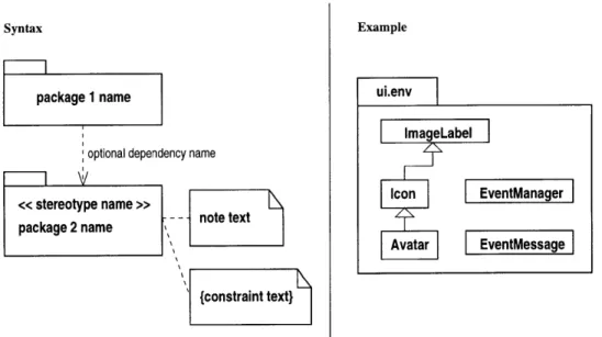
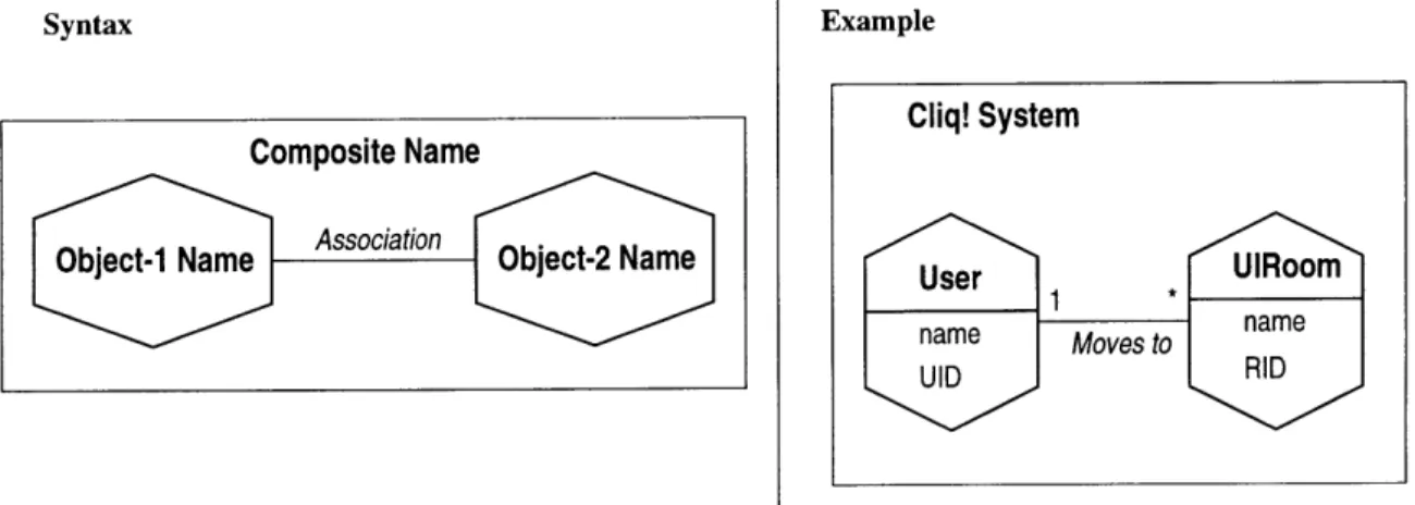
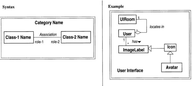
3-17 Constraints ... ... ... 3-18 Composite Representation . . . . 3-19 Category Representation . . . . ..
3-20 Use Case Representation . . . ... 3-21 Message Trace Diagram Representation . . 3-22 State Diagram Representation . . . . 3-23 Module Diagram Representation . . . . 3-24 Platform Diagram Representation . . . . . 4-1 Microsoft's NetMeeting . . . ...
4-2 Vocaltec's Internet Conference Professional 4-3 Connel University's CU-SeeMe . . . . 4-4 Netscape Conference . . . .. 4-5 Farallon's Look@Me ...
4-6 Worlds Chat's 3D User Interface . . . . 5-1 Groupware Software Product Domain, Ad
15.5641 ... ...
5-2 Importance of Social Interaction . . . . 5-3 Social Interaction Components . . . . 5-4 Personal Expression Components . . . . . 5-5 Social Feedback Components . . . . 5-6 Components of Social Interaction . . . . . 5-7 Social Interaction Components in the Ying-5-8 Comparison between Social and Casual Int
6-1 Suggested User Interface . . . . . . . . . .. . . . . . 106
115.564, Information Technology I is a course from MIT Sloan School of Management, taught by Professor Chrysanthos Dellarocas. . . . . . . . . . .. . 59 .. . . . . . . . 60 .. . . . . . . 61 . . . . . . . . 62 . . . . . . . . . 63 . . . . . . . 64 .. . . . . . . . 65 .. . . . . . . 65 . . . . . . . . . 69 . . . . . . . . . 7 1 . . . . . . . 72 .. . . . . . . . 73 . . . . . .. . 75 .. . . . . . 76
ipted from lecture note of .. . . . . 82 . . . . . . 83 .. . . . . . . . 84 .. . . . . . 85 . . . . . . . 89 .. . . . . . . . 92 -Yang Model . ... 95 eraction Tool . ... 96
LIST OF FIGURES
Cliq! System Architecture Overview . . . . Client/Server Model of Cliq! . . . .. Casual Contact Interaction Model . . . . Casual Contact User Interface . . . . Three Conditions of Casual Contact . . . . Dataflow Diagram of the Client/Server Model Network Module Object Diagram . . . . Emotions and their Meanings in the System Relationships Between User Interface Classes User Interface Object Diagram . . . . . ....
. . . . . . . . . 115 . . . . . . . . 117 . . . . . . . . 118 . . . . . 119 . . . . . . . 120 . . . . . 121 . . . . . . . . 122 . . . . . 124 . . . . 127 . . . . . . . 129
7-1 Suggested Software Engineering Model for Distributed Development Window of the Server Monitor . . . . Initial User Interface Window . . . . Network Activities Status Monitor . . . Main User Interface Window of Cliq! . Chat and Expression Toolbar . . . . Library with a Door to Main Hallway List of Rooms where the User Can Go Dialog Box to Introduce the Name of the New Room D-9 Expressions in the Chat Window . . . . . 158 . . . . . . 159 . . . . . 159 . . . . . 160 . . . . . . 161 .. . . . . . 162 . . . . . 163 . . . . . 163 . . . . . . 164 D-10 Valid Emoticons and Their Relationship with the Expressions
D-11 Emoticon Embedded in a Message ... . . . . . . .. 6-2 6-3 6-4 6-5 6-6 6-7 6-8 6-9 6-10 6-11 132 D-1 D-2 D-3 D-4 D-5 D-6 D-7 D-8 165 165
List of Tables
3.1 Activies and Goals of Design Phase . . . .. 3.2 Tool Categories . ... ... 3.3 Work Plan and Time Table . ... ... 3.4 Programming Styles and Abstractions . . . . 4.1 Product Evaluation Summary ...
6.1 Netstat Output . ... ... 6.2 Structure of User Interface Event Manager Message 6.3 Server Side Event Identification . ...
6.4 Room Identifier Mapping . ...
7.1 Pros and Cons of Working with a Distributed Team
A.1 A.2 A.3 A.4 A.5 A.6 A.7 A.8 A.9
User Registration Use Case . . . . . . . . .
Ideal Course of Action for User Registration .. .... Alternate Courses of Action for User Registration . . . Modify User Profile Use Case . ... . ...
Ideal Course of Action for Modifying User Profile . . .
Alternate Course of Action for Modifying User Profile . User Login Use Case ... ...
Ideal Course of Action for User Login . . . . Alternate Course of Action for User Login . . . .
.. . . . 37 . . . . . . . 41 .. . . . 42 .. . . . . . 45 .. . . . 67 . . . . . . 118 . . . . . 126 . . . . . . 126 .. . . . . 128 136 .. . . . . 138 . . . . . 139 . . . . . 139 . . . . . . 139 . . . . . 140 . . . . . 141 . ... 141 . . . . . 142 . . . . . 142
LIST OF TABLES 12
A.10 Create Room Use Case ... ... . 143 A.11 Ideal Course of Action for Create Room . ... 143 A.12 Alternate Course of Action for Create Room . ... 143
Chapter 1
Introduction
This thesis is developed from the studies in the Distributed Software Engineering Lab-oratory (DISEL). In this labLab-oratory, students from Centro de Investigaci6n Cienifica y de Educaci6n Superior de Ensenada (CICESE) and Massachusetts Institute of Tech-nology (MIT) collaborate in the development of a medium scale software project. Each participant plays a role within the software development cycle of the project.
This laboratory proposes a new perspective of distance education by having stu-dents experience a professional product development process. At the same time, students would focus on the collaborative nature of his/her learning experience while working with each other over distance to gain further insight to the existing problems within collaborative learning. The class is modeled in resemblance to a real software company, where each student will be involved in one or more specific roles, such as Project Manger, Analyst, Software Designer, Programmer, Quality Control Engineer, Validation and Verification Engineer, Maintenance Engineer and Documentation Spe-cialist.
To promote the entrepreneur spirit, the team's project proposal was entered to the MIT's Entrepreneurship 1K Competition. The feedback from the judges in the competition were positive and encouraging, showing the possibilities of a business application of the project.
CHAPTER 1. INTRODUCTION
This chapter will serve as an introduction to the domain of work in distributed system design and collaborative learning. The motivation of solving some commonly known social and casual interactions problem in distant communication will be pre-sented. The remainder of this thesis is divided into six chapters, each covering a piece in defining and solving the distance communication problem.
In Chapter two, a general overview of three fundamental concepts will be intro-duced. These concepts include collaborative learning and software engineering. The definition of software design and its purpose within software engineering will also be discussed in depth.
Chapter three describes the background of the project, the motivation of develop-ing a software to solve the distance education and collaborative learndevelop-ing problem. A brief coverage of the Unified Modeling Language (UML) notation and conventional Object-Oriented Design will be provided. A section of this chapter will also be de-voted to explain the role of design, its related theories, methodologies, and processes that were used in this research.
Chapter four examines some current existing distance communication tools, such as the popular NetMeeting and the game-like 3D World Chat. Comparisons of the DISEL system with each of these tools will also be given in this section.
Chapter five covers the requirement analysis for the DISEL product. The work was mainly conducted by the analysts of the team, Semonetta Rodriguez and Humberto Chavez. The presentation of requirement analysis can give reader a sense of what is to achieve through this project. It is also a yard stick for performance and quality measurement of the design and implementation.
Chapter six proceeds to the core of the DISEL system design, details of an ex-tensive collection of documents will be presented. Those include the requirement analysis for the research, design document, system feature document, system archi-tecture model, object model, and quantitative specification.
CHAPTER 1. INTRODUCTION
from both a technical and interpersonal point of view. It will provide some insights of distance development difficulties, not to mention, some very rewarding experience as well. This chapter also draws a conclusion of the distributed software design for collaborative learning. Issues of feasibilities and future improvements will be discussed.
1.1
Importance of Distance Learning
The terms "distance education" or "distance collaborative learning" have been ap-plied interchangeably by many different researchers to a great variety of programs, providers, audiences, and media. Its hallmarks are the separation of teacher and learner in space or time, the willful control by the student in learning rather than the distant instructor, and noncontiguous communication between student and teacher, mediated by text, graphics, audio or video.
Until recently, the use of traditional non-interactive or transmissive media in dis-tance education only provided trainers with the option of pedagogic methods in which individual learning is predominant. Learners in distant geographical locations were left isolated and, thus, deprived of learning methods that originated from interactive communication in a close social setting. Hence, there is a desperate need in developing system that will enable social or cognitive interactions.
Collaborative learning, generally considered to be a method reserved exclusively for face-to-face situations, is now possible to implement through distance education. Many view the popular video conferencing as a successful approach to distance learn-ing. However, if one examine the concept of social interaction closely, using video conferencing to communicate is greatly flawed. Social interaction is constituted of three elements: social feedback, casual contact, and personal expression. It is clear that, the first and last of the these are directly related to each other, and they are crucial for establishing lasting bond between connected parties. The signals, such as
CHAPTER 1. INTRODUCTION 16 facial expression, speech tone, and hand movement can proved to be very valuable in delivering intentions during conversation. An ideal learning system will provide an environment that will allow uninhibited social interactions and free information sharing. The Figure 1-1 below expresses the concepts of social interaction in context of collaborative distance learning.
Unplanned Session
/ Social Feedback Ill
I ' / I I "-,/ / I I\ \ / Personal I , Expression,' I I, Interaction
Figure 1-1: Social Interaction
The distance learning problem does not just attract academic attention, policy makers and the general public are also increasingly interested in solving this problem. Once it is solved, the solution will be an extremely valuable option for communications between remote areas. Distance learning allows users to hear or see the instructor's teaching, as well as allowing teacher to react to his audience's comments and ques-tions. Moreover, virtual learning communities are not bounded by locations, and they can be as close as co-located learning groups.
CHAPTER 1. INTRODUCTION
the problem is how to create and maintain trusting and lasting bonds between people. How do one create an virtual environment that will enable distant social interaction seemed local? The question is challenging, because there is no definite answer for it. One has to engage himself to understand the problem, define the problem and then proceed to solve the problem. This thesis will provide some insights and techniques for such a process.
1.2
Objective
The distance learning software application developed by the DISEL group is aimed at providing a solution to the problem. The current techniques and technologies for conducting distance learning and distributed project collaboration contains signifi-cant deficiencies. There is severely limited or non-existing social interaction between participants in these applications. For example, the chat room environment that exists on the web is largely used to communicate information, but users of these chat rooms do not view the connection as a representation of their truthful thoughts. Many times these users use false identities to conceal themselves, and the textual information they exchanged serve more as an entertainment purpose rather than an educative one.
The goal of the project is to enforce a meaningful and realizable social interaction between distant parties that are using the DISEL system. Unlike the chat rooms, it is intended to provide educational services. The system will connect people across data network, and allow them to engage in conversations, meetings, lectures, and discussions. The virtual environment implemented will give individuals freedom to express themselves without the constraints of the machine. In addition, users can experience virtual classroom or meeting situations through electronic means, that will not deviate greatly from the real ones.
CHAPTER 1. INTRODUCTION
1.3
Benefits
Major effort of the system will be devoted to provide casual interaction services to the users. There are a lot of existing implementations on the market that have par-tial distant planned interaction solutions. For example, the Microsoft Netmeeting application can transmit video and audio across the Internet, and it also allows users to share graphics. However, all conversations conducted in NetMeeting are planned. Users are prepared to engage in such interaction. In Contrast, a casual interaction is not planned. It is a form of communication where users meet with someone uninten-tionally in a virtual setting. The possibilities to have an unstructured conversation between users are greatly beneficial. It will bring the individual distance learning experience one step closer to the real thing.
One important element of distance learning research is about human thinking. It is an integral part of the distance education. Clearly, it is essential to consider human factors thoroughly in a complex system that will provide casual and planned interactions. Though this thesis will not discussed distance learning in psychological perspectives, nevertheless, the study of human behavior in this type of communica-tions is necessary. Most importantly, distance learning is not an isolated phenomenon, it is affected by the political, social, financial and technological factors in its environ-ment. As a result, the understanding of the influence and scope of distance education will benefit many people.
In the next chapter, the discussion will shift to focus on some practical distributed system concepts and system methodologies to solve the collaborative learning problem presented here.
Chapter
2
Concepts, Methodologies, and
Theories
2.1
Overview of Software Engineering
Software Engineering is a discipline for software development, it is a combination of using comprehensive methods in each developing phase, and better tools for au-tomating these methods. In short, software engineering provides powerful building blocks for implementation, and good techniques for software quality assurance, work coordination, time or resources control [28].
2.1.1
Definition of Software Engineering
The definition of software engineering can be boiled down to one sentence: The establishment and use of sound engineering principles in order to obtain software that is reliable and works efficient on real machine [22].
Software engineering contains a set of three key elements - methods, tools and procedures. These key elements enable the manager to control the process of software development. In the following section, we will briefly examine each of them.
CHAPTER 2. CONCEPTS, METHODOLOGIES, AND THEORIES
Methods
Software engineering methods provide the technical how to for building software. Methods involve a broad array of tasks that include project planning and estima-tion, system and software requirement analysis, design of data structure, program architecture, and algorithm procedure coding, testing and maintenance. Methods for software engineering often introduce a special language-oriented or graphical notation and introduce a set of criteria for software quality [2].
Tools
Software engineering tools provide automated or semiautomated support for methods. Today, tools exits to support each of the methods noted above. A system for the support of software development, called computer-aided software engineering (CASE) is established to streamline this process. CASE combines software, hardware, and a software engineering database to create a software engineering environment that is analogous to the popular computer-aided design (CAD) system for hardware [11].
Procedures
Software engineering procedures are the glue that holds the methods and tools to-gether and they enable rational and timely development of computer software. Pro-cedures define the sequence in which methods will be applied, the deliverables that are required, the controls that help to ensure quality and coordinate change, and the milestones that enable manager to access progress [24].
Altogether, these three steps are called the software engineering paradigms. Many times, a paradigm is chosen based on the nature of the project and application, the method and tools to be used, and the controls and deliverables that are required. There are three widely discussed paradigm, and a short description of each is provided in the following sections.
CHAPTER 2. CONCEPTS, METHODOLOGIES, AND THEORIES
2.1.2 Classic Software Life Cycle
Each software development cycle goes through a number of stages, these stages are stepping stones for others. They are also good indicators of the development process. These stages include: system engineering analysis, software requirement analysis, design, coding, testing, and maintenance.
System Engineering Analysis: The process of establishing requirements for all system elements and then allocating some subset of these requirements to soft-ware. This step is necessary only if software is a module of the entire system. Software Requirement Analysis: The process of collecting crucial information
about the product from the customers. Requirements define what need to be implemented.
Design: The step that translates requirements to a representation that software can
be assessed on. It defines the four distinct attributes of the program: data structure, software architecture, procedural detail, and interface characteriza-tion.
Coding: The step of translating design to machine understandable format.
Testing: The process that ensure the software functions perform correctly, and
reli-ably.
Maintenance: An on going process to enhance existing features of the software, and adapt external changes for smooth integrations.
In practice, not all the stated steps are necessary, and not all of them have to follow the restricted order given above. Here, three classic software development processes will be presented, and each would have its own advantages over others in certain situation.
CHAPTER 2. CONCEPTS, METHODOLOGIES, AND THEORIES
Waterfall Model
The waterfall mode illustrates a systematic sequential approach to software develop-ment. The process begins at the system level and progresses through analysis, design, coding, testing, and maintenance. This model is simple and straight forward for ac-tual practice, however it is not without flaws. Many times, iterations are necessary in real-life projects, and this model's structure is too rigid to reflect these type of activ-ities. In addition, the mode requires completion of each step before going to the next stage, increasing the cost of later modification. Although there are problems with the waterfall model, it is still the most basic and easiest to understand template among the three paradigms that will be discussed here [24, pages23-36]. An illustration of the waterfall model is provided in Figure 2-1.
CHAPTER 2. CONCEPTS, METHODOLOGIES, AND THEORIES
Prototyping
Prototyping is a process that enables the developers to create a model of the software that must be built. It offers a better approach to situations with general objectives but no detailed requirements [7]. The model helps developers to perceive the pos-sibilities to realize the feasibility of refining the prototype. The sequence of events for the prototyping paradigm is shown in Figure 2-2. Like all approaches to software development, prototyping begins with requirement gathering, then a "quick design" occur. The quick design leads to the construction of a prototype. The prototype is evaluated by the customer/user and is used to refine requirements for later version of the same piece of software. A process of iteration continues until the prototype is tuned to satisfy all the user's needs.
CHAPTER 2. CONCEPTS, METHODOLOGIES, AND THEORIES
Spiral Model
The spiral model is developed to use the best features of the waterfall and prototyping models [3, pages 61-72]. In addition, the risk analysis is added to the model. The process illustrated in Figure 2-3 is represented by four major activities:
Planning - determination of objectives, alternatives, and constraints.
Risk analysis - analysis of alternatives and identification/resolution of risks.
Engineering - development of the next-level product.
Customer evaluation - assessment of the results of engineering.
The model provides a clear picture of developing reliable software while keeping the cost in check. As each iteration around the spiral completes, the software progresses gradually. If initial prototype reveals major problems of the product, the project can terminate right away, and the risk of complete failure at the end is minimized [14].
2.1.3
Generic View of Software Engineering
The software development process contains three generic phases regardless of the soft-ware engineering paradigms that is chose [24]. The three phases: definition, devel-opment, and maintenance are encountered in all software disciplines despite different application areas, project sizes, complexities, or resources. Therefore the overview of these three phases is important, it will give us an universal view of the characteristics of software development.
Phase one: Definition
The definition phase focuses on what. That is during definition, the software developer will attempt to identify what information is to be collected, what functions and performance are desired, what interfaces are to be established, what design constraints
CHAPTER 2. CONCEPTS, METHODOLOGIES, AND THEORIES
Plai cust
lecision
stem
Figure 2-3: Spiral Model Diagram, Adapted from [24, page 232].
exist, and what validation criteria are required. The key requirements of the system and the software are identified. Altogether, three steps will occur in this phase, system analysis, software project planning, and requirement analysis.
Phase two: Development
The development phase focuses on how. That is, during development, the developer will attempt to define how data structure and software architecture are to be designed, how procedural details are to be implemented, how the design will be translated into a programming language, and how testing will be performed. The methods applies may vary, but the three specific steps are unchanged: software design, coding and testing.
CHAPTER 2. CONCEPTS, METHODOLOGIES, AND THEORIES
Phase three: Maintenance
The maintenance phase focuses on change. Associated with error correction, adapta-tion required as the software environment evolves and enhancement brought about by changing customer requirements. The maintenance phase reapplies the same steps of the definition and development phases, but does so in the context of exiting software. The three types of changes that happen in maintenance are:
1. Correction - bug tracking and defect repair.
2. Adaptation - modification to software to accommodate changes in its external environment.
3. Enhancement - adding functions/features that are beyond the original require-ment.
The importance of these concepts, especially those that link to the role of designer will be reiterate in Chapter 3, where object-oriented design framework is presented. After introducing the definition of software engineering, discussions of Collaborative Learning will be presented in the following section. Since the goal of the project is to design a workable collaborative learning system, defining the meaning of collaborative
learning is essential.
2.2
Collaborative Learning
Collaborative learning is an activity described as group attempting to work together toward a common goal [15, pages 167-178]. Though this statement may not be ac-curate for current on-line experience, it does cover a wide range of possibilities of different collaborative efforts through distance communication.
CHAPTER 2. CONCEPTS, METHODOLOGIES, AND THEORIES
2.2.1
Definition
Collaborative learning as an intentional teaching and learning strategy has seen tremendous growth in the past twenty years. It has been formally developed, studied, and evaluated in a wide range of spectrum. The technique of collaborative learning is separate into five elements: positive interdependence, face-to-face interaction, indi-vidual accountability, interpersonal skills, and group processing [27, pages 137-146]. The study in this thesis remains closely related to the first two elements.
1. Positive interdependence
Fostering a positive interdependence among group participants is very impor-tant to a successful collaborative learning experience. Group member need to feel they need each other to accomplish the task at hand. This can be achieved through establishing goals mutually conceived, negotiated and agreed upon by the group. Establish joint rewards to be received by all members is another aspect helps to create an environment of positive interdependence. Shared in-formation and materials are equally important to the group in so far as this provides a basis for members to have insight into the overall task and to e assis-tance to each other. The final aspect contributing to positive interdependence is the assignment of individual roles. Each person must understand the part they play and their relationship to the whole project. The presences of these aspects are important to insuring a successful collaborative learning experience. 2. Face-to-face communication
As traditionally perceived, collaborative learning involves face-to-face commu-nication. Verbal interactions taking place among students and lecturers of the experience are important. This is a process that incur the most substantial transformation when moving to the computer-mediated environment. Interac-tion is broken down to separate textual and visual cues, where it is up to the individual on both side to assemble the elements back together to construct a
CHAPTER 2. CONCEPTS, METHODOLOGIES, AND THEORIES
realistic image. Figure 2-4 illustrates this process.
Bits of information
9
"--6-%
d
-
----
Iton of audio video text InTormation Information Channel in Computer-based MediateFigure 2-4: Computer Mediated Face-to-Face Interaction
2.2.2
Problems with Distance Collaborative Learning
Sys-tem
As it is described above, the two most important elements in successful collaborative learning is the positive interdependence experience shared among the group members and the face-to-face communication between participants. However both requirements need members to physically co-located in one place. The difficulty of replicating the traditional collaborative learning experience through electronic media is how to implement an effective interface. The information one wants to transmit is translated to machine understood data to deliver to the distant party. The interface between machine and human is crucial in correctly interpreted the human reaction and filter out the non essential elements. A human can be considered as a black-box which transmits different signals to the other world. How those signals can be processed is up to each individual that receives them. The task of the interface is not to filter or interpret those signals, but to deliver them without modifications.
CHAPTER 2. CONCEPTS, METHODOLOGIES, AND THEORIES 29
There are no good ways of building such machine-human interface. The closest replication of the collaborative experience is video conferencing. Though such sys-tem is capable of delivering the visual and audible information, it is not capable of delivering subtle mood changes of users. Evidently, the need to have machine and human interaction also creates a barrier between distant parties. Individuals may feel reluctant to voice opinion to people on the other side and visa versa. These barri-ers are removable through better undbarri-erstanding of the interface between human and machine, and through careful construction of better learning implementations.
Chapter 3
Research Background
The objective of DISEL is to build a system that will improve the existing distance learning system, such as the video conferencing and on-line chatting. None of these systems provide means for users to form lasting bonds that are based on collabora-tions. Instead of stressing on replicating face-to-face conversational experience, the system we develop will focus on two aspects of distance communications: social and casual interactions. Social interaction possesses standard parameters that are similar to those of a meeting environment. For example, the conversation, the body gesture, the facial expression, and other signals of people that will be used in a typical meeting. On the other hand, there is the notion of casual interaction, the not so formal encounter between persons. How do we differentiate the nature of social and casual interaction? The simplest concept is that casual interaction involves no intention and expectation. For example, if you walk into a local supermarket, you don't expect to see your professor there, however, if you do meet him, you will try to strike a conversation that is within context. The effect of this context related conversation is very important, you might find out information that you won't get from class. These bits of information may not help you in understand the lecture better, but it certainly is an eye opener for you. It's guarantee that you will view your professor differently the next time in class, because now you know him as a person. Such knowledge is
CHAPTER 3. RESEARCH BACKGROUND
beneficial for human bonding, it is brought forward by casual interactions.
In another example, say you meet with a colleague at the water cooler, who is working on the same project with you. You start a common "Hi-Bye" conversation, and it smoothly diverge to a discussion of your current progress on the project. These types of conversation came about without initial planning, but they do serve purposes in improving communications among team members. I shall classified these category of interactions as the bathroom, coffee machine or water cooler phenomenon.
If casual interaction is important, why is it missing from all the products that are on the market now? One simple answer is that, casual interaction is hard to replicate. If the event does not happen randomly, it will just become another subset of social interaction. Securing the randomness of such event is difficult to achieve, and there is no better approach known so far. Therefore, there exist vast opportunities in the area of casual interaction through distance communications. We believe this enhancement will greatly affect how people communicate and behave on line. In return, such feature will help pushing technology one step further in making virtual experience real.
3.1
Research Motivation
The join effort in experimenting the collaborative distance learning between MIT and CISECE is the main driving force behind this project. Each student will take on a specific role in the software development cycle. In this report, materials will focus on the role of designer for this distance learning system.
Though the need of developing an useful application is the first priority for the project, the purpose of learning through out the process is high up in our agenda. A successful completion of DISEL product may be important, however, the positive experience of each individual can take home after the class is even more important. The true motivation of engaging a group of students in the distance learning project is to help identify the problem in current system, and to come up with new solutions.
CHAPTER 3. RESEARCH BACKGROUND
The ability of implementing those solutions are minor compare to the abilities to look into the right area, and ask the right questions that will induce imagination and creativity.
3.2
Research Description
The research team is formed with entrepreneur spirits. In fact, the group of students are viewed as members in a software company. The professors server the role of clients who came to the team for solutions to their technical problems. To be consistent with the terms that were used before, the team will be called DISEL team, and the product that is developed is called the Cliq! system.
The following information is based on a collection of documents that are produced from the project. You should be able to gain a good perspective of the purpose and goal of the project from the materials provided below. Also keep in mind that the specialty of my participation in this research is software design. The majority of materials presented in this chapter will be very much design related.
3.2.1
Team Vision
We are living a revolution whose motor is the convergence between computing and communications. This group proposes to assume a leading role, making technolog-ical contributions that impel this revolution. In particular through the successfully developing of a software system that fulfills the specified requirements of functional-ity, cost and calendar, using modernized human and technological resources, both of them geographically distributed.
CHAPTER 3. RESEARCH BACKGROUND
3.2.2 Team Mission
3.2.3
Participants
The team is composed of fifteen members. Six students from MIT, and nine students from CICESE. The division of the role is based on both personal preferences and the logical workload distribution. The organization chart (Figure 3-1) will illustrate this role division relationship.
3.2.4
Role of Designer
In every engineering discipline, design encompasses the disciplined approach we use to invent a solution for some problem, thus providing a path from requirements to implementation. In software engineering the purpose of design is to construct a system that meets the following issues:
* Satisfies a given functional specification. * Conforms to limitations of target medium.
* Meets implicit or explicit requirements on performance and resource usage. * Satisfies implicit or explicit design criteria on the form of the artifact.
* Satisfies restrictions on the design process itself, such as its length or cost, or the tools available for doing design.
Our mission is carrying out us in a professional way, committed with the vision of the group. Each member will assume the assigned role with responsibility and high level of communication and motivation that propitiates a pleasant atmosphere of work. We will express our doubts and problems freely and will be willing to listen and help.
CHAPTER 3. RESEARCH BACKGROUND
MIT CISECE
Instructors
Feniosky Pena-Mora Jesus Favela Josephina Rodnguez
Project Managers Bob Yang (head)
Analysts
Simonetta Rodridguez (head) Humberto Chavez
Designers
Rene Navarro (head)
Chnstine Su
Programmers
Kareem Benjamin Bob Yang
Chnstine Su
Quality Control Engineers
Charles Njendu (head) Simonetta Rodridguez
Testing Engineer
Juan Contreras
Validation and Verification Engineers
Gregorio Cruz Lidlia Gomez (head)
Software Configuration Engineer
Marcela Rodndguez
Documenation Specialist
Diana Ruiz
Maintenance Engineer
Juan Francisco
Figure 3-1: Participant Organization Chart
Objective of Design
The purpose of design is to create a clean and relatively simple internal structure, sometimes also called an architecture. A design is the end product of the design process. Thus, one goal of software design is to derive an architectural rendering of a system. This rendering serves as a framework from which more detailed design activities are conducted.
Good software architectures tend to have several attributes in common:
* They are constructed in well-defined layers of abstraction, each layer
repre-Sergio Infante (head)
CHAPTER 3. RESEARCH BACKGROUND
senting a coherent abstraction, provided through a well-defined and controlled interface, and built upon equally well-defined and controlled facilities at lower levels of abstraction.
* There is a clear separation of concerns between the interface and implementation of each layer, making it possible to change the implementation of a layer without violating the assumptions made by its clients.
* The architecture is simple, common behavior is achieved through common ab-stractions and common mechanisms.
The flow of information during the design phase is illustrated in Figure 3-2. Soft-ware requirements, manifested by informational, functional, and behavioral models, feed the design step. Using one of a number of design methods, the design step produces a data design, an architectural design, and a procedural design. The data design transforms the information domain model created during analysis into the data structures that will be required to implement the software. The architectural design defines the relationship among major structural components into a procedural description of the software. Then source code is generated, and testing is conducted to integrate and validate the software.
The importance of software design can be clarified with a single word - quality.
De-sign is the place where quality is fostered in software that can be assessed for quality. Design is the only way that one can accurately translate a customer's requirements into a finished software product or system. Software design serves as the foundation for all software engineering and software maintenance steps that follow. Without design, one risks building an unstable system that will fail when small changes are made. It also causes numerous difficulties in testing and quality assessment later in the software engineering process.
CHAPTER 3. RESEARCH BACKGROUND functional model information model Data Design behavior model other requirer Procedural Design Program grate and date Software
Figure 3-2: Design, Coding and Testing Flow Diagram, Adapted from [24].
Activities and Goals of Design
In order to evaluate the quality of a design representation, we must establish technical criteria for good design. The following guidelines may be useful, also see the items summarized in Table 3.1:
1. A design should exhibit a hierarchical organization that makes intelligent use of control among elements of software.
2. A design should be modular, that is, the software should be logically partitioned into elements that perform specific functions and subfunctions [4].
3. A design should contain both data and procedural abstractions.
4. A design should lead to modules (e.g., subroutines or procedures) that exhibit independent functional characteristics.
-CHAPTER 3. RESEARCH BACKGROUND
Table 3.1: Activies and Goals of Design Phase
Activity Goal
Create a system internal structure, so called Subsytem Decomposition an architecture and definition of relations
among subsystems.
Set global resources To select the appropriate policies for logical namimg, access management space, physical units, and shared data access.
Choose data storage To select the appropriate storage method for data management technique structures. e.g. Data structures vs file system vs DBMS Interact with the To select the appropriate language and
programmers programming paradigm
Subsystem allocation to Assign processes to processor units that serves processors as a platform for subsystem execution
Concurrency Identify those case where system execution management involves multiple threads of control
Control strategy Determine appropriate method for lines of execution selection control. e.g. Procedural vs Event driven vs Concurrent
Ensure that modules operate properly at
Boundary conditions boundaries established to limit or restrict processing. management Initializations, termination, and failures
5. A design should lead to interfaces that reduce the complexity of connections between modules and with external environment,
6. A design should be derived using a repeatable method that is driven by infor-mation obtained during software requirements.
Design Decomposition
Software design is conducted in two steps [24, pages 318-321]. Preliminary design is concerned with the transformation of requirements into data and software architec-ture. Detail design focuses on refinements to the architectural representation that lead to detailed data structure and algorithmic representations of software. In addition to data, architectural, and procedural design, many modern applications have a
dis-CHAPTER 3. RESEARCH BACKGROUND
tinct interface design activity. Interface design establishes the layout and interaction mechanisms for human-machine interaction.
Object-Oriented Design
Object-Oriented Design (OOD) encompasses the process of object-oriented decom-position and a notation for depicting both logical and physical as well as static and dynamic models of the system under design; specifically, this notation includes class diagrams, object diagrams, module diagrams and process diagram [9].
Here are some information about principal OOD methodologies:
* Booch: This method defines different models to describe one's system. The
logical model or problem domain is represented in the class and object structure. In the class diagram, one can construct the architecture. The object diagram shows how the classes interact with each other, it captures some moments in the life of the system which helps to describe the dynamic behavior.[6]
* Fusion: A systematic software development method for object-oriented software that was developed at Hewlett-Packard Laboratories in Bristol, England. The method integrates and extends the best features of earlier methods, including OMT, Booch and CRC. Fusion is a full-coverage method, providing a direct route from a requirements definition through analysis and design to a program-ming language implementation.[12]
* Shlaer-Mellor: A well-defined and disciplined approach to the development of industrial-grade software. It is based on the object-oriented paradigm, and has developed over the past dozen years in the pragmatic environment of real-world projects. These projects have included manufacturing and process con-trol applications, intelligent instruments and peripherals, banking operations, telecommunications, and defense applications.
CHAPTER 3. RESEARCH BACKGROUND
* OMT: An object-oriented design technique that provides a method for repre-senting software design. The method consists of several notations, one of them being a diagramming technique for representing classes and their relationships. As such, it has built-in concepts for attributes, class inheritance, and class re-lationships.
* Unified Modeling Language: An application modeling language for use-case modeling, class and object modeling, component modeling, and distribution and deployment modeling.
Relation with the other Roles
Through the software development process we observe a high degree of interaction among system design and the different key process areas.
Analyst Designer translates specification of requirements established in requirement analysis into an model of implementation. Interact with the analyst to deter-mine project feasibility. Usually analyst assists designer and vice versa.
Programmer Designer creates the system implementation blueprints for
program-mers. This model is translated into a machine readable form during encoding process. Designer assists programmer in programming language selection and interpretation of design documents such diagrams, charts, tables, etc. etc.
Test Engineer Designer coordinate efforts with test engineer in order of assure that
architectural design of software system includes specifications that helps in test cases exercise. Assists test engineer in requirements verification.
Quality Control Quality control engineer reviews design phase in order of ensure
design process products quality and fulfills performance, design, and verification requirements.
CHAPTER 3. RESEARCH BACKGROUND
Validation and Verification Engineer Validation and verification engineer
assess-ments the level of accordance between client requireassess-ments and the system's model of implementation designed, looking for misunderstood, missing or wrong implemented features.
Documentation Specialist Documents specialist keep design documents once that
design process is completed and makes this document available for the rest members of the development team.
Software Configuration Manager During design, software configuration manager
controls design changes and maintains complete records of every change and its rationale.
Maintenance Engineer Designer assists maintenance in managing of post delivery
evolution. This evolution comprises bug fixes, system functionality enhance-ments, and requirements modifications.
Project Manager Designer works under coordination of project manager in order
of build a system architecture that meets requirements under given budget constrains and availability of human resources. Additionally, project manager
uses design specifications for planning and estimate resource allocation.
Tools
There are many valuable software design tools available on the market, they generally provide vast functionalities of planning and process complex software projects. Table 3.2 lists some popular CASE toolsets that are used in a wide spectrum of platforms.
Designer Profile: Who should play the role?
* For small and medium size systems, architectural design is typically the respon-sibility of one or two particularly insightful individuals. They must have that unusual ability to synthesize workable solutions amidst a myriad of constraints.
CHAPTER 3. RESEARCH BACKGROUND
Table 3.2: Tool Categories
Company Tool Name Platforms Description and
Supported Methodologies Supported
Hewlett HP, HP CASE tool integration,
Packard C++/Softbench C/C++ development Iconix Iconix Power Macintosh, Multiuser, 00 development Software Tools Windows, Dos, toolset, OMT
Engineering HP, Sun, SGI and Booch
Mark V ObjectMaker MS-Windows, Object-oriented Software Unix, Macintosh analysis and design,
Booch
Popkin System MS-Windows, Object-oriented design Software Architect OS/2 design, Booch, Shlaer/Mellor Platinum Paradigm Plus Windows, Unix, CASE toolset supporting
Technology OS/2 OMT, FUSION, Booch,
Shlaer/Mellor and Customized methods
Rational Rose Unix, AIX Object-oriented analysis and design Booch, OMT, and UML
* Designers are usually the best qualified to make strategic decisions due their previous experience in building similar systems.
* Designers are no necessarily the most senior developer. * Designers should have adequate programming skills.
* Designers should be well versed in the notation and process of object-oriented development.
Work Plan
A successful project can not come without a work plan. The work plan is a guide line for development, and it is a yard stick for progress measurement. The design phase of the DISEL project lasted about 40 days. It started on January 10, 1998, and ended
CHAPTER 3. RESEARCH BACKGROUND
Table 3.3: Work Plan and Time Table
Activities Time (Days)
System Design 20
Organize the system into subsystems 3 Identify concurrency inherent in the problem 2 Allocate subsystem to processor and task 2 Choose data storage management 2 Identify global resources and determine access mechanisms 3 Choose an approach for implement execution control 5 Consider boundary conditions 3
Object Design 20
Obtain operations for the object model from other models 7 Design algorithms to implement operations 1 Optimize access paths to data 1 Implement software control 3 Verify class structures to increase inheritance 2 Design implementation of associations 3 Determine the exact representation of object attributes 2 Package classes and associations into modules 1
on March 22, 1998. Table 3.3 is a detailed listing of the activities conducted within the design phase.
3.2.5 Object Oriented Approach
Like any specialized field of research, object technology has accumulated its own set of terms and definitions. This specialized language is often an obstacle for new people attempting to understand objects. Thus, the following section is provided to pave away such obstacles and to help readers to become familiar with object technology terms.
Object Oriented Concepts
A software object is used to represent some real world entity, such as a part number or an address, which the system must manipulate. An object is defined as a software
CHAPTER 3. RESEARCH BACKGROUND
package which contains a set of related data, and all the functions and procedures needed to access and modify that data. The data is often referred to as the object's state. The functions are called the object's methods. Calling one of an object's methods is often referred to as sending a message to that object, requesting that the object provide some services.
Classes
Programs rarely require a single object with unique state and methods. It is much more common to manage collections of objects which share methods and state, and differ only in the values of their state variables. If two or more objects share the same methods and state variables, they are said to be members of the same class. They might also be referred to as instances of that class. For example, a bank might have an account object which keeps track of the account number, owner's address and balance. Each real account held by the bank would be represented by a single instance of the account class.
It is important to distinguish between a class and an object. A class is simply the definition of what data is stored in instances of that class and what operations are available for manipulating that data. An object is the item which stores the data, and exists inside the program. A class can be thought of as the blueprint and operating instructions for its objects.
Inheritance
An application will often manipulate several very similar classes of objects. For example, the previous banking application (see Section 3.2.5) might have checking, savings, and money market accounts. If each of these were implemented as a class, there would be much overlap between the three classes. They would share state variables like account number, owners name, address, and balance. They would also share many methods like deposit, withdrawal, and add co-signer.

![Figure 2-1: Waterfall Model Diagram, Modified from [24, page 226].](https://thumb-eu.123doks.com/thumbv2/123doknet/14751863.580568/22.918.165.740.556.877/figure-waterfall-model-diagram-modified-from-page.webp)
![Figure 2-2: Prototyping Model Diagram, Adapted from [24, page 228].](https://thumb-eu.123doks.com/thumbv2/123doknet/14751863.580568/23.918.273.625.559.903/figure-prototyping-model-diagram-adapted-page.webp)
![Figure 2-3: Spiral Model Diagram, Adapted from [24, page 232].](https://thumb-eu.123doks.com/thumbv2/123doknet/14751863.580568/25.918.127.765.178.538/figure-spiral-model-diagram-adapted-from-page.webp)

![Figure 3-2: Design, Coding and Testing Flow Diagram, Adapted from [24].](https://thumb-eu.123doks.com/thumbv2/123doknet/14751863.580568/36.918.177.708.176.590/figure-design-coding-testing-flow-diagram-adapted.webp)