A Distributed Flight Control System
Architecture for Small UAVs
by
ENS Ryan Bruce Norris, USN
B.S. Systems Engineering
United States Naval Academy, 1996
Submitted to the Department of Electrical Engineering and Computer Science
In Partial Fulfillment of the Requirements for the Degree of
MASTER OF SCIENCE IN ELECTRICAL ENGINEERING
AND COMPUTER SCIENCE
at the
MASSACHUSETTS INSTITUTE OF TECHNOLOGY
June 1998
© 1998 Ryan Bruce Norris.
All rights reserved.
Y~~en~hePh~ssaXsvfrmP"
~ c:i!4rr
~7rrl,~s Bpr~~l ~ L.C "' d i-' i-'i-' ij'' ri ~P~il~T~ I~jti ~f7 C--r.Signature of Author
Approved by
Certified by
Accepted by
Department of Electrical Engineering and Computer Science
May 20, 1998
Dr. David S. Kang
Project Manager, Charles Stark Draper Laboratory
,
•Technical
Supervisor
SDr.
John J. Deyst, Jr.
fessor of
onautics
and Astronautics
'tT sis Advisor
Arthur C. Smith
Chairman, Committee on Graduate Students
Department of Electrical Engineering and Computer Science
Architecture for Small UAVs
by
ENS Ryan Bruce Norris, USN
Submitted to the Department of Electrical Engineering and
Computer Science on May 20, 1998, in Partial Fulfillment of the
Requirements for the Degree of Master of Science in Electrical
Engineering and Computer Science
Abstract
The current practice for designing a small unmanned aerial vehicle (UAV) flight control
system is to use a traditional centralized processing architecture.
Because of its
characteristic lack of modularity, this type of architecture does not satisfy the need for
frequent upgrades, replacements, and redesigns of vehicles and their subsystems in the
most time-and-cost-effective manner. This thesis explores the potential of a data
bus-based, distributed processing architecture, to better meet that need.
A hypothetical centralized architecture is generated representing a current practice
baseline for small UAV architectures. The benefits of utilizing a distributed architecture
for the small UAV flight control system are analyzed, and some design methods and
relevant technologies are discussed. Specifically, two distributed flight control system
architectures are presented:
a LONWorks (Local Operating Network) control bus
architecture and a Universal Serial Bus (USB) high performance serial bus architecture.
To demonstrate the relative advantages of the distributed approach, a set of metrics is
used to compare the costs of altering the centralized architecture and the USB
architecture, when the specific system must be redesigned or the system must be
expanded with an additional flight control sensor.
Technical Supervisor: Dr. David S. Kang
Title: Project Manager, Charles Stark Draper Laboratory
Thesis Advisor: Dr. John J. Deyst, Jr.
Many individuals helped contribute to the success of this thesis, and I would like to extend great thanks to each and every one of them:
First, I would to thank my three thesis advisors from the Draper Lab: Dave Kang, Paul Rosenstrach, and Bob Powers. Dave was my advisor during the two years I spent at Draper and I thank him for giving me the opportunity to work in the Intelligent Unmanned Vehicle Center at Draper. Dave and Paul were great advisors during the research phase of my thesis. Dave never let me loose sight of the big picture, and Paul taught me the importance of not making assumptions. He would always push me to research a subject until I fully understood it. Bob was an excellent advisor when it came time to write my thesis. He was always available to read and comment on sections of the thesis, and he taught me a great deal about writing a good technical paper. I would also like to thank John Deyst, my advisor at MIT, for taking the time to read and comment on my thesis.
Many of the references for this thesis came from discussions I had with engineers at the Draper Lab. They were always willing to make time in their day to meet with me, and their opinions on various subjects guided me in my research. I would like to extend thanks to the following engineers at the Draper Lab:
Brent Appleby Bruce Dow Bob Leger Tom Thorveldson Bob Butler John Dowdle Mark Prestero Paul VanBrokhoven Jim Connelly Dave Hanson Gary Schwartz Skip Youngberg Paul Debitteto Tony Kourepenis Mike Socha
The two years that I spent at Draper gave me a chance to work with many other students, and at the same time, make some great friends. I would like to thank the students at Draper with whom I worked. I learned a great deal from many of them, and they made the work at Draper fun and interesting. Specifically, I would like to thank Chuck Tung, Christian Trott, Mohan Gurunathan, and Bill Kaliardos. Chuck, Christian, and Mohan were always available for advice on anything electrical, Mohan gave away his secrets on taking great digital pictures, and Bill always had time to talk and give suggestions concerning any thesis problems I was having.
I would like to thank the librarians at Draper for their patience and help in finding many of the references I used for this thesis.
I would like to thank all of my friends and family. Their love and support has motivated me over the years of my education. I would especially like to thank my beautiful wife Zoe. Her smile and ability to make me laugh can always turn a bad day into a good day. I dedicate this thesis to her.
Finally, I would like to thank God for giving me the opportunity to enjoy life and continue to learn day after day. Because of him, all of this is possible.
This thesis was prepared at The Charles Stark Draper Laboratory, Inc., under IR&D Contract #13316.
Publication of this thesis does not constitute approval by Draper or the sponsoring agency of the findings or conclusions contained herein. It is published for the exchange and stimulation of ideas.
Permission is hereby granted by the Author to the Massachusetts Institute of Technology to reproduce any or all of this thesis.
LIST OF FIGURES ...
11
LIST OF TABLES ...
13
CHAPTER 1...15
1.1
M otivation ... ... 15
1.2 Unmanned Vehicles...
15
1.3
M odularity ...
16
1.4 DOTS ...
17
1.5
The Modularity Advantage: a ULV Case Study ...
17
1.5.1
EOD Architectural Design...
18
1.5.1.1
System Components ... 18
1.5.1.2 W iring and Interconnection of Components ...
... 20
1.5.2 EOD Architectural Problems and Solutions ...
...
21
1.6 A pproach ... ... 23
CHAPTER 2...25
2.1
Narrowing The Application...
25
2.2 Defining Vehicle Requirements ...
27
CHAPTER 3...
... ... 31
3.1 Traditional Architectures ...
... 31
3.2 Defining New Requirements ... ...
... 33
3.3 Initial Architectural Conclusions... ...
35
CHAPTER 4 ...
37
4.1
Data Bus Characteristics...
37
4.1.1
T opology ... 38
4. 1.1.1
The Ring ...
38
4.1.1.2 T he Star ...
... 39
4.1.2 Interfaces... .. ...
... ...
... ... 40
4.1.3 T he O SI M odel ... ... 4 1
4.1.4 Sm art N odes ... ... 42
4.2 Data Bus Technology ... 44
4 .2.1
C ontrol B us ...
45
4.2.2 High Performance Serial Bus ...
46
4.2.3 Why Not 1553? ...
47
4.3 LONWorks ... 48
4.3.1
L O N W orks N ode... 49
4.3.2 LONTalk Protocol ... 51
4.3.3 Communications and Power ... ... ... 51
4.3.4
LONWorks Control Module...
...
52
4.4 U niversal Serial B us ...
... 53
4.4.1
USB Topology ...
53
4.4.2 USB Host ...
...
55
4.4.3 USB Transactions and Bus Protocol ... .. .. 58
4.4.4 Power ... .... ... ... 58
4.4.4.1
Bus-Powered Hub ...
... 58
4.4.4.2
Self-Powered Hub ... 59
4.4.4.3 Bus-Powered Function ... 59
4.4.4.4 Self-Powered Function ... 59
4.4.4.5 Voltage Requirements...
60
4.4.5
Latency and Timing...
... 60
CHAPTER 5 ...
...
65
5.1 SCPB Flight Control System... 65
5.2 Ideal Solution ... ... 68
5.3 LONWorks Solution... 69
5.3.1
LONWorks Architectural Design ... 69
5.3.2 LONWorks Bandwidth Analysis ...
72
5.4 U SB Solution...
... ... 73
5.4.1
USB Architectural Design ...
73
5.4.3
USB Bandwidth Analysis ...
... 76
CHAPTER 6 ...
79
6.1 Functional Factors ...
... 79
6.2 Cost Factors ...
82
6.2.1 New Design Costs ...
84
6.2.2 System Upgrade Costs ... ...
85
6.3
Conclusions ... ... 86
CHAPTER 7 ...
89
APPENDIX A ...
... ... 93
FIGURE 1-1: THE EOD MICRO-ROVERS... 19
FIGURE 1-2: EOD MICRO-ROVER WIRING DIAGRAM ... 20
FIGURE 1-3: WIRING DIAGRAM FOR A BUS-BASED EOD MICRO-ROVER ... 22
FIGURE 2-1: PAYLOAD AND WINGSPAN OF EXISTING UAVs ... 25
FIGURE 2-2: RANGE AND ENDURANCE OF EXISTING UAVs... 26
FIGURE 3-1: TRADITIONAL CENTRALIZED PROCESSING ARCHITECTURE... 32
FIGURE 3-2: INTERCONNECTION OF TRANSDUCERS... 34
FIGURE 4-1: RING TOPOLOGY FOR A DATA BUS ... ... 39
FIGURE 4-2: STAR TOPOLOGY FOR A DATA BUS ... ... 39
FIGURE 4-3: TREE TOPOLOGY FOR A DATA BUS ... ... 40
FIGURE 4-4: BANDWIDTH AND COMPLEXITY OF DATA BUS TECHNOLOGIES...45
FIGURE 4-5: NEURON MICROCONTROLLER BLOCK DIAGRAM ... 49
FIGURE 4-6: LONWORKS NODE ... 50
FIGURE 4-7: LONW ORKS CONTROL M ODULE ... 52
FIGURE 4-8: U SB TOPOLOGY ... ... 54
FIGURE 4-9: USB FOUR WIRE CABLE... 54
FIGURE 4-10: USB HOST COMPONENTS AND DATA CONVERSION PROCESS ... 55
FIGURE 4-11: U SB H UB ... 57
FIGURE 4-12: VOLTAGE DROP TOPOLOGY ... ... 60
FIGURE 4-13: NRZI ENCODED DATA... 62
FIGURE 4-14: WORST CASE TOTAL ROUND TRIP DELAY ... 62
FIGURE 5-1: SCPB SUBSYSTEM INTEGRATION DIAGRAM... 66
FIGURE
5-2: SCPB
SUBSYSTEM INTERCONNECT DIAGRAM...67
FIGURE 5-3: IDEAL ARCHITECTURE FOR A DISTRIBUTED FLIGHT CONTROL SYSTEM... 69
FIGURE 5-4: LONWORKS DISTRIBUTED FLIGHT CONTROL SYSTEM ARCHITECTURE... 70
FIGURE 5-6: USB DISTRIBUTED FLIGHT CONTROL SYSTEM ARCHITECTURE ... 74 FIGURE
5-7:
USB FRAME FOR FLIGHT CONTROL SYSTEM DATA ... 77 FIGURE6-1:
COSTS FOR REDESIGNING AND UPGRADING A FLIGHT CONTROL SYSTEM .... 86THE EOD MICRO-ROVER SYSTEM COMPONENTS ...
19
UAV REQUIREMENTS ... 28
INTEGRATED NAVIGATION SYSTEM REQUIREMENTS...
29
THE OSI MODEL FOR COMMUNICATION SYSTEMS...
42
LONWORKS TRANSCEIVER TYPES ... ... 51
USB CHARACTERISTICS AND ESTIMATED PROTOCOL OVERHEAD ...
61
SCPB NAVIGATIONAL SUBSYSTEM REQUIREMENTS... 68
INTEL
USB
CHIP SPECIFICATIONS ...75
USB INERTIAL INSTRUMENT AND GPS BANDWIDTH CALCULATIONS... 77
TRADITIONAL VERSUS USB FUNCTIONAL FACTORS... 80
ADDED VOLUME OF
USB
SYSTEM COMPONENTS ... 81TRADITIONAL VERSUS USB COST FACTORS ...
83
NEW DESIGN COSTS FOR TRADITIONAL AND USB ARCHITECTURES... 84
SYSTEM UPGRADE COSTS FOR TRADITIONAL AND USB ARCHITECTURES ... 85
TABLE 1-1: TABLE 2-1: TABLE 2-2: TABLE 4-1: TABLE 4-2: TABLE 4-3: TABLE 5-1: TABLE 5-2: TABLE 5-3: TABLE 6-1: TABLE 6-2: TABLE 6-3: TABLE 6-4: TABLE 6-5:
Chapter 1
Introduction
1.1
Motivation
The increasing variety of missions on which unmanned aerial vehicles (UAVs)' are being deployed, and the rapidly advancing technology of flight control sensors, both indicate a coming need for frequent upgrades, replacements, and redesigns of these vehicles and their subsystems. Because of its inflexible nature, the traditional centralized architecture used in many existing UAVs will not satisfy this need in the most time and cost effective manner. As the sensors, actuators, or other control components required for particular missions change or become outdated, a distributed architecture would allow for easy substitution and replacement of those components. This plug-and-play concept would save some of the time and money that are normally put into redesigning and constructing a new vehicle whenever these changes occur.
1.2 Unmanned Vehicles
Over the past century, the U.S. has assumed the role of peacekeeper of the world. To uphold this role in the 2 1st century, our nation must maintain an effective military capable of deploying forces for a variety of purposes, in many parts of the world, in a timely and effective manner. The ability to rapidly obtain information about the enemy can benefit mobile forces in mission areas such as reconnaissance and surveillance, battle damage assessment (BDA), target designation, and nuclear, biological, and chemical (NBC) detection. Success in these areas, however, often requires knowing the conditions of the battlefield before forces actually arrive there. Unmanned vehicles can aid immensely in this task.
Three classes of unmanned vehicles exist: the unmanned land vehicle (ULV), the unmanned underwater vehicle (UUV), and the unmanned aerial vehicle (UAV). Information
Chapter 1: Introduction
concerning the conditions of a battlefield can be rapidly obtained with air reconnaissance missions. Consequently, there is great interest in UAVs.
UAV missions are generally flown to cover areas determined to be too hazardous or expensive for manned reconnaissance aircraft. U.S. Military operations in Grenada, Lebanon, and Libya, in the early 1980s, identified the need for an on-call, inexpensive UAV [7]. Thus, the
Pioneer UAV was developed in the mid 1980s and has since flown missions in the Persian Gulf
and Bosnia. Currently, the U.S. funds six major UAV programs and supports research in many related areas. Recent UAV developments have caused the U.S. government to define requirements for UAVs to support an increasing variety of operations and identify a need for different classes of UAVs to support these operations [22].
Different missions require different levels of performance from a vehicle, and it is almost impossible to design a single vehicle capable of supporting all possible missions. Current UAV design practice falls short of meeting the implied challenge: rapid and economical adaptation to changes in mission requirements.
1.3
Modularity
The dictionary defines a module as: a separable component [of a system], frequently one that is [easily] interchangeable with others ... [20]. In general, a module refers to a device within a larger system that performs a given function to support the overall function of the larger system. This module function can be described by the output of the device in relation to some input to the device. The user of the device (e.g. the flight control computer) is not concerned with the internal components and overall operation of the device, but rather the information the device or module provides as output or the information that must be supplied to the device or module as input. If the module must be replaced or upgraded, the flight control computer will not care if a different module replaces the old module, just as long as the new module provides the computer with correct information or readily accepts the information provided by the computer. As defined here, a modular system is a system in which many modules can easily be connected to or removed from a central control computer. In general, the more modular a system is, the easier it will be to adapt an old system to meet new requirements and missions. The interface between a module and the flight control computer, as well as the interface between two modules, usually determines the difficulty of connecting and disconnecting modules to and from the flight control computer and to each other. In general, the more standardized an interface is within a system,
the easier it will be to reconfigure and expand the system, and the higher the modularity will be for that system.
Updating an old vehicle to perform a new mission could be accomplished with a modular flight control system. A modular flight control system could be used across several different vehicles by reconfiguring it to accommodate specific missions, thus reducing the development costs of designing a new vehicle every time a new mission is encountered. A modular flight control system could easily accommodate changes in technology as well. With the rapid technological pace of today, when the sensors aboard an aircraft become outdated, they can be replaced by current, up-to-date sensors, without redesigning the entire system.
1.4
DOTS
Much of the motivation for the research involving a modular UAV was provided by a project at the CSDL called "Draper Off-the-Shelf (DOTS)". The primary goal of the DOTS project was to develop off-the-shelf subsystems to strengthen total system development market potential by minimizing development cost and time over the life of a product. Given an application with market potential for Draper, the overall objectives of this project were to select a candidate DOTS subsystem, identify and compare methods to satisfy a range of requirements at minimum development cost and time, and if possible, develop a prototype system using these methods. The application chosen for review was the UAV, and because of broad interest within Draper, the UAV flight control system was selected as the candidate DOTS subsystem.
1.5 The Modularity Advantage: a
ULV
Case Study
The concept of modularity is by no means only applicable to the flight control system of a UAV. The vision of a modular control system can be extended to other unmanned vehicles as well. In fact, the experience gained from working with other students on the architectural development of a highly centralized ULV has indicated a need for system modularity to ease the ongoing development and maintenance of the vehicle.
Since the start of the decade, different series of ULVs have been designed and built at the Intelligent Unmanned Vehicle Center (IUVC) of the Charles Stark Draper Laboratory
Chapter 1: Introduction
(CSDL) in Cambridge, Massachusetts. The most recent series of vehicles are those known as the EOD (Explosive Ordnance Disposal) Micro-Rovers.
The EOD rovers are intended for use in the detection and retrieval of unexploded ordnance (UXO). The EOD rovers must be able to perform several tasks which include: building a hazard map, navigating to within 1 m2 of the UXO, precisely locating the explosive, picking up the UXO, and carrying the explosive to a disposal site. The EOD rovers are similar in design to the MITy-x series of rovers which were also designed and built at the IUVC at Draper. Two rovers were built for the EOD project, EOD-1 and EOD-2. EOD-1 is a tele-operated system, which serves to show the mobility capabilities of the mechanical platform as well as the option for tele-operated control. EOD-2 is envisioned as a fully autonomous system that can complete an assigned task with minimal operator assistance. This case study will present the basic architecture implemented for the EOD rovers as well as the problems associated with the
architecture which motivated the research for a more robust, efficient, and modular design.
1.5.1
EOD Architectural Design
1.5.1.1
System Components
The EOD vehicles are equipped with a six-wheel drive flexible frame, a front and rear Ackermann steering system similar to that used on automobiles, and a grappler device for UXO retrieval. The EOD micro-rovers are shown in Figure 1-1.
The flexible frame of the EOD micro-rovers provide it with a high degree of maneuverability, enabling the rover to traverse rocks, curbs and uneven terrain. The frame is constructed of three individual platforms connected by spring steel wire. Table 1-1 summarizes the vehicle components for both EOD-1 and EOD-2. EOD-1 is used primarily for parallel development purposes and it shares the same basic mechanical architecture with EOD-2, but it lacks a complete sensor suite and grappler mechanism.
The components are housed in the three individual vehicle platforms. The front platform contains the two degree of freedom grappler mechanism, the metal detector unit, the sonar, and the front bumper sensors. The middle platform houses the main processor, the video camera and transmitter, the wireless modem, the local positioning system transponder, and the micro-mechanical rate gyro. The rear platform contains the power regulation circuitry, the motor driver electronics, and the batteries.
Figure 1-1: The EOD Micro-Rovers
Component
EOD-1
EOD-2
Six-wheeled, three-platform mechanical architecture 0 0 Six drive wheel motors with integrated encoders * * Grappler mechanism for retrieval of UXO *
12 MHz Z-World Little Giant Microprocessor with 512 KB SRAM and PIO096 Expansion Board
Systron-Donner micro-mechanical gyroscope * Video camera and transmitter * 0
Front bumper sensors *
Local Positioning System (LPS) * Polaroid sonar ranging module array *
Proxim wireless modem 0
Metal Detector 0
Chapter 1: Introduction
1.5.1.2
Wiring and Interconnection of Components
The EOD micro-rovers were designed using a traditional centralized architecture approach in which every sensor and actuator throughout the system is connected directly to the main central processing unit (CPU). The characteristics of a centralized architecture will be discussed in greater detail in Chapter 3.
The main processor of the EOD micro-rover is located on the center platform of the vehicle. The main processor is a 12 MHz Little Giant microcontroller that is based on the Zilog Z180 microprocessor. An input and output (I/O) expander board is used as well to accommodate the number of digital I/O lines required to interface to the many sensors and actuators. This main processor stack stores and executes the micro-rover's main program and is responsible for the following tasks: collecting data from the sensors, processing the navigation and control algorithms, commanding the actuators, and communicating with the ground station.
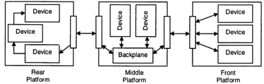
A simplified version of the EOD wiring diagram is shown in Figure 1-2. As was previously stated, the system was implemented using a traditional centralized processing architecture and each peripheral device in the system uses a number of dedicated data lines which connect it to the CPU. The vehicle is broken into three platforms. Each platform has a DB50 data connector and a DB50 power connector, allowing the platforms to be easily connected and disconnected. The data connector carries the low current signals that connect the sensors to the CPU while the power connector carries the high current signals that drive the motors. Inside the center platform is a backplane through which all the wires to and from the CPU must pass. Should the processor fail, this design allows it to be easily replaced.
Although the EOD system architecture seems very simple and modular to some level, its highly centralized architecture made it difficult and very frustrating to develop and maintain. The next section will discuss some of the problems encountered with the architecture as well as
possible solutions.
Device e a Device
Device
Device
Device cplane Device
Rear Middle Front
Platform Platform Platform
1.5.2
EOD Architectural Problems and Solutions
Throughout the construction, development, programming, and maintenance of the EOD micro-rovers, various problems were discovered which led to the perceived desire for possible
architectural changes to alleviate the problems.
During programming, problems began to arise with the Little Giant microprocessor. The Little Giant was having difficulty processing all of the low level driver code required for each peripheral in addition to the high level behavioral code required for the vehicle navigation and control algorithms. Initially, to relieve this burden on the Little Giant, the high level tasks were moved to the ground station and the rover lost the ability to perform its own path-planning and navigation, without ground station assistance. Eventually, a decision was made to replace the Little Giant microprocessor with a 486 processor running at 50 MHz-the Intel x86 based processor. This type of processor possesses much more computing power than the Little Giant and would allow the path-planning and navigation code to remain on-board the rover. However, there was one major problem associated with the x86 based processor. Unlike the Little Giant, which has many digital and analog I/O ports for directly controlling each peripheral, the x86 based processor has only two serial ports and relies on the addition of expansion cards for additional I/O ports. To avoid the addition of these expansion cards, to accommodate the various sensors and actuators, it was determined that a different method for communication was desired.
Because of the central processing architecture used on the vehicle, the intensely burdensome task of low level hardware management was placed on the main processor. The sensors communicate all raw data to the main processor where it is processed into meaningful data which can then be used by the high level algorithms. In a similar manner, the actuators would receive low level hardware commands directly from the main processor. This burden can be relieved by distributing the processing load. A dedicated embedded microcontroller placed at each sensor and actuator would allow any of the high bandwidth control loops to be performed locally at the specific peripheral devices. The sensor or actuator with the embedded microcontroller becomes a "smart" node; this idea will be discussed further in Chapter 4. Essentially, the CPU is required to only send higher level commands to each device in a predefined data format and the process by which those commands are carried out is left to the microcontroller at each device. With respect to modularity, this concept allows easy substitution and interchanging of sensors and actuators. Because of the predefined data format, the CPU will
Chapter 1: Introduction
always communicate with a specific sensor or actuator in the same manner. When a sensor or actuator must be substituted into the system, the only major task is to program the locally embedded microcontroller to transform the device data into the proper format.
The final problem encountered on the EOD rover was due to the wiring architecture. The centralized processing architecture required dedicated data lines for each peripheral device and each device was wired directly into the CPU. The disadvantages associated with this type of approach include: large numbers of dedicated I/O lines, difficult documentation and debugging, and high material and labor costs. The large number of wires caused a major inconvenience during the construction phase of the rovers. A team of students was dedicated, for over a week, to the task of crimping the approximately 2,000 wire crimps necessary. Also, because of the many wires run throughout the system, it was very difficult to locate wiring problems when they occurred. It was not uncommon for two students to spend an entire day trying to locate a faulty wire. Sometimes the documentation was not up to date and this would exacerbate the problem. It was determined that the best way to alleviate this problem was through the use of a data bus; the data bus will be discussed in Chapter 4. A data bus allows the different sensors and actuators, throughout the system, to share the same transmission medium, when communicating with the CPU, thus reducing the total number of wires run throughout the system and reducing the cost and time to manufacture the product as well.
A fellow student from the IUVC has designed a system which implements the previously mentioned architectural changes for the EOD micro-rovers [21]. A simplified version for the updated wiring diagram would be similar to that in Figure 1-3. As will be explained in Chapter 4, a data bus is limited by the maximum bandwidth it can support. Devices can be added to the data bus as long as the rate at which information must be passed to or from the device does not exceed the maximum bandwidth of the bus. This allows the system to be readily expanded and developed.
Device Device
Device Device
DeviceDevice
Rear Middle Front
Platform Platform Platform
With these ideas in mind, and guided by the lessons derived from the EOD rover experience, it will be feasible to develop and present an improved architectural approach for a UAV flight control system.
1.6 Approach
The work of this thesis can be broken down as follows:
* Identify a span of system level requirements for a class of UAVs. An initial list of vehicles will be considered and this list will be narrowed through an elimination process based on criteria such as mission, size, or Draper production potential for specific vehicles. Next, traditional requirements will be defined for the specific UAVs chosen. Traditional requirements refer to general system requirements such as size and weight as well as instrument requirements such as the drift of inertial instruments. Finally, a set of desired requirements or characteristics for an alternative architecture will be defined.
* Determine the optimum level of standardization and select the best architecture to satisfy the defined requirements. Initially, it was assumed that adopting an architecture which would allow such characteristics as modularity and expandability would require some sort of standardization. The degree of standardization will have to be determined as well as the best method to implement standardization. Data bus technology offers many benefits in this context.
* Analyze and draw conclusions based on a predefined set of metrics for the proposed architecture versus a traditional centralized architecture. In order to effectively measure the validity of an alternative architecture, a list of metrics will have to be established. Using these metrics will allow conclusions to be drawn on two major issues: the expected development cost and time over the life of a product in the event of a system redesign or expansion.
Chapter 1: Introduction
The goal of this thesis is not to point out major design flaws in existing systems, but rather to study the existing systems and gain insight into the overall design and decision processes. The vehicles examined were each originally designed with one specific purpose or mission in mind and the architecture chosen for the vehicle best accomplished that mission. However, when multiple purposes or missions are considered and a design must be tailored to many platforms, in the most timely and cost effective manner, these existing architectures are impractical. Therefore, an alternative architecture that best meets these multiple missions or needs must be defined.
Chapter 2
Requirements Definition Process
2.1
Narrowing The Application
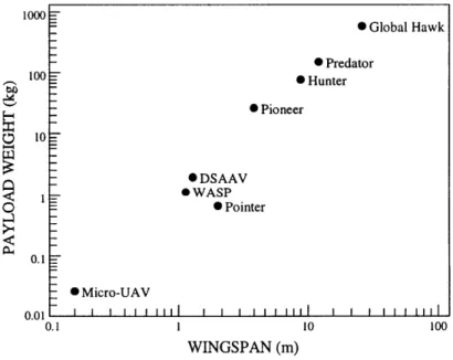
Examining the missions and requirements of different existing UAVs is a good first step in architectural development. This type of examination will reveal advantages and disadvantages of different vehicles and their architectures, and allows conclusions to be drawn which can then be used to narrow the class of UAVs under study. Figure 2-1 below gives the reader an idea of the relative size of a variety of existing UAVs. They are compared by wingspan of the aircraft and the weight of the payload the aircraft will carry. Figure 2-2 on the following page also gives the reader an idea of the relative mission characteristics for the same UAVs. It compares the mission duration or the endurance of the vehicles with the range of the vehicles.
0.1
rJru1
-0.1 1 10 1
WINGSPAN (m)
Figure 2-1: Payload and Wingspan of Existing UAVs
* Global Hawk 0 Predator 0 Hunter 0 Pioneer *DSAAV * WASP 0 Pointer - Micro-UAV I I I I I IIIl I I I IIii I I I II I l I I I I I lll
Chapter 2: Requirements Definition Process
The UAVs considered in the study were:
* Global Hawk - a fixed-wing high altitude endurance UAV used by U.S. forces
* Predator - a fixed-wing medium altitude endurance UAV used by U.S. forces
* Hunter - a fixed-wing tactical UAV used by U.S. forces * Pioneer - a fixed-wing tactical UAV used by U.S. forces
* Pointer - small fixed-wing UAV used by U.S. Army and U.S. Marine Corps
* Draper Small Autonomous Aerial Vehicle (DSAAV) - small rotary-wing aircraft used at Draper
* Wide Area Surveillance Projectile (WASP) - Draper funded, guided munition project at MIT
* Ultra-light - class of very light fixed-wing aircraft
* Micro-UAV - proof of concept study being conducted by the Defense
Advanced Research Projects Agency (DARPA)
40-Global Hawk 30 20 - • Predator Pointer Z _* Hunter 10- Micro-UAV / SAAV Pioneer 0 1 1ASPIi I i i I I lii l I I I 1 1 1 I 11 10 100 1000 10000 RANGE (km)
This list of vehicles was narrowed down to a much smaller group of vehicles. The endurance vehicles were eliminated from the study because their very large airframe made them unrealistic for production by Draper. Further research indicated that it would even be unrealistic for Draper to be the prime contractor for aircraft the size of Hunter or Pioneer, and they were eliminated from the study as well. The Ultra-light class of vehicles was eliminated because the placing of expensive electronics on a cheap airframe seemed unrealistic. Due to a lack of information on its navigational system requirements, the Pointer was also eliminated from the study. The remaining aircraft, in order by size, included: the Micro-UAV, the WASP, and the
DSAA V.
In summary, the aircraft under study were narrowed down to a group of "small" UAVs for the reasons mentioned. In addition, no commercial off-the-shelf (COTS) flight control systems were found to meet the requirements and missions for these vehicles. The elimination of the larger tactical and surveillance vehicles was driven by the fact that many COTS flight control systems are already in production for this class of vehicles. There is heavy competition between larger prime contractors in this area and the vehicle program scale would be unrealistic for Draper to get involved in.
2.2
Defining Vehicle Requirements
After narrowing down the application to a small class of UAVs, the next step was to gather requirements for these specific aircraft, examine those requirements, and draw conclusions about different methods to use in order to satisfy the range of requirements across the different vehicles.
All three vehicles have some level of autonomy which is provided by the flight control system. As stated before, the Micro-UAV is still being researched by DARPA and the requirements are therefore still preliminary. The aircraft is small enough to fit in the palm of a human hand and its primary mission is surveillance-another possible use would be NBC detection. The mission of the WASP can be divided into two sub-missions. It is a precision guided munition which transforms itself into a fixed-wing aircraft to be used for surveillance. The requirements used for the WASP in this thesis will cover the guided munition portion of the mission. The DSAAV is an autonomous helicopter whose primary missions are object and vehicle recognition and small object retrieval.
Chapter 2: Requirements Definition Process
A large list of requirements for the three vehicles was generated. In order to initially narrow the flight control system study, the navigational subsystem was chosen as the primary subsystem to examine. Therefore, the requirements gathered included both the physical aircraft requirements and the navigational subsystem requirements. The navigational subsystem requirements included primarily the requirements for the GPS and inertial subsystems. A condensed list of the requirements can be seen in Table 2-1 below. It includes only those requirements from the original list that had any significant meaning and were useful for comparing the vehicles.
Parameter
Micro-UAV
WASP
DSAAV
Max Endurance (hrs) 1 0.1 0.5
IMU Weight (ibs) 0.02 0.11 1.96
IMU Volume (in3) 1 5 33.5
IMU Input Voltage (V) TBD +12, +5 ±15 IMU Power (W) < 5 3 7
IMU Shock (g) TBD 16000 200 (peak)
Gyro Bias Magnitude (deg/hr) 3600 18000 156
Accelerometer Bias Magnitude (g) TBD < 2 0.006 Table 2-1: UAV Requirements
Two conclusions were drawn from analyzing these requirements. First, instrument performance and utilization vary widely. Second, there is a great difference in the mentioned requirements based on the missions of the three UAVs studied. Requirements which varied the greatest were volume, weight, shock, endurance, and the bias magnitude for the gyros and accelerometers. These conclusions led to the following question: could a single flight control system satisfy the span of all vehicle requirements without too much over-kill?
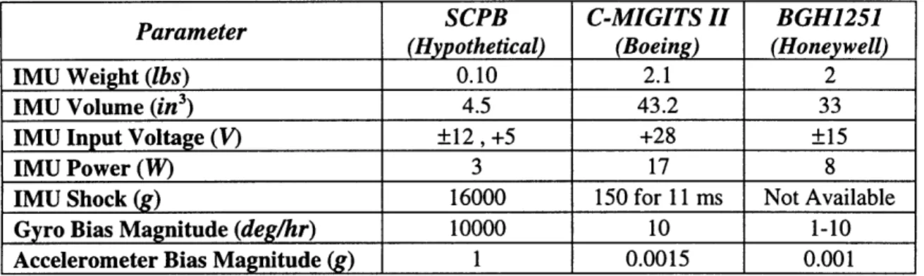
In order to answer this question, three systems were examined. The three systems included a hypothetical centralized flight control system and two COTS flight control systems: the C-MIGITS II, a miniature integrated GPS/INS tactical system from Boeing, and the BGH1251, a miniature flight management unit from Honeywell. The hypothetical system is based on the current practice in small UAV flight control system design and will be referred to as the Small UAV Current Practice Baseline (SCPB). The requirements gathered for the systems were similar to the those gathered for the vehicles and included the physical requirements of the system as well as the performance requirements of the navigational components. A condensed
list of the requirements is shown in Table 2-2. It includes only those requirements from the original list that had any significant meaning and were useful for comparing the systems.
SCPB
C-MIGITS II
BGH1251
(Hypothetical)
(Boeing)
(Honeywell)
IMU Weight (lbs) 0.10 2.1 2
IMU Volume (in3) 4.5 43.2 33
IMU Input Voltage (V) ±12 , +5 +28 ±15
IMU Power (W) 3 17 8 IMU Shock (g) 16000 150 for 11 ms Not Available
Gyro Bias Magnitude (deg/hr) 10000 10 1-10 Accelerometer Bias Magnitude (g) 1 0.0015 0.001
Table 2-2: Integrated Navigation System Requirements
A number of conclusions were drawn based on the two previous tables. First, the COTS
systems are too large and power hungry to satisfy small UAV requirements. The BGH1251 does come very close to satisfying the requirements for the DSAAV. This instrument, however, cannot satisfy the requirements for the other two vehicles because of its large size. Next, it was concluded that the SCPB flight control system would satisfy the requirements for the WASP but not the DSAAV or the Micro-UAV. This is a result of the mission duration and the bias magnitude for the inertial instruments-a longer mission will require more precise inertial instruments.' Furthermore, because the SCPB system is a centralized, point design solution, higher bandwidth sensors such as vision-based navigation may overload the system.2 Substitution of a more precise inertial instrument into the SCPB flight control system could allow the system to meet the requirements for the DSAAV and the Micro-UAV, solving the problem.
The conclusions drawn from the requirements definition process have suggested something about the vehicle and existing system architectures. In fact, the process can actually be viewed as a proof of concept for initial assumptions that were made about flight control system architectures. The major assumption was that the traditional centralized architecture, under which most flight control systems of today are designed, would be impractical for tailoring a design to many platforms in the most timely and cost effective manner. This assumption has
' It is assumed that the threat of GPS jamming exists.
Chapter 2: Requirements Definition Process
been verified by the conclusions drawn in this chapter. Specifically, the existing centralized flight control systems examined could not meet the requirements of multiple vehicles. As a result, an alternative architecture would have to be defined, and the conclusions suggest that a scalable architecture that preserves the prior design, but allows for sensor and processor improvements, is a good approach.. The following chapter builds on this approach and looks at flight control system architectures in order to draw initial conclusions on implementation methods.
Chapter 3
Traditional Flight Control System
Architectures
The conclusions drawn from the requirements definition process suggest an approach for satisfying the span of requirements across the vehicles. That approach is a scalable architecture which preserves the prior design of the system, but also allows for component improvements throughout the life of the vehicle. This chapter will build on that suggestion by examining flight control system architectures. First, the current practice in these architectures will be analyzed and conclusions will be drawn based on traditional architectures. Next, alternative architectures that will satisfy a list of desired characteristics will be considered. This step will include exploring different methods of connecting transducers to a CPU, defining the desired system characteristics, and finally drawing conclusions on the different ways to achieve those characteristics.
3.1
Traditional Architectures
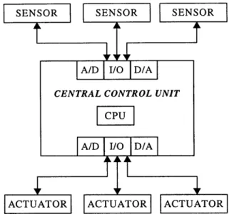
Flight control systems are traditionally designed using a centralized processing architecture. In fact, a majority of the small UAV flight control systems being used today are still designed using this approach. The design focuses around a single central control unit (CCU), where a main CPU is used to perform all of the sensor fusion, navigational algorithms, and other computational tasks. Generally, the CCU will have multiple analog and digital 1/O pins to which the transducers' are wired directly. Figure 3-1 shows the overall layout of such an architecture. As described, the CCU is at the center of the diagram, with the transducers branching off from the
I/O pins.
Chapter 3: Traditional Flight Control System Architectures
SENSOR SENSOR SENSOR
A/D I/O D/A
CENTRAL CONTROL UNIT
A/D I/O D/A
ACTUATOR ACTUATOR ACTUATOR
Figure 3-1: Traditional Centralized Processing Architecture
There is one major advantage to this particular architecture. If a designer has one
particular purpose in mind, or a single list of requirements to meet, very high performance of the system can usually be obtained. For example, when it is determined that a system must be designed to tackle a single mission, the designer may concentrate all of his or her efforts on designing a system that will best perform that particular mission. In technical terms, the designer "custom designs" the system to best meet his or her needs. However, if in the future, the designer must adapt this custom design to perform additional missions, he or she will likely find this to be a difficult task. The major disadvantages of traditional architectures are that they are inflexible, they are not modular, and they are not expandable.
This can be due to a number of reasons. First, the system could have a specific limited
CPU capacity. This could come in the form of the number of 1/O pins available, the amount of
memory available, or the speed at which the CPU is capable of running the system.
Next, substitution of transducers will impact all specific hardware and software interfaces. For example, suppose that the system contains some general transducer with specific system requirements (e.g. power, I/O, signal conditioning circuitry). Now, suppose a decision has been made to upgrade that transducer with a more sophisticated sensor with the same general purpose. On the hardware side, this might require an additional power rail to be run through the system. If all the 1/O lines are already committed, circuitry must be designed to extend the 1/O of the CCU. Also, the connectors used to interconnect the various components may be full, requiring a mechanical alteration of the system to run additional connectors. Finally, this
mechanical alteration may require more changes in the electrical system. A similar result occurs on the software side as well. When the low-level software used to control the transducer is rewritten, changes in the higher-level software may be required as well. These domino effects end up wasting time and money, and they can possibly be avoided with the implementation of an
alternative architecture [1].
Finally, because the transducers are directly wired into the CCU, and possibly to each other, many wires will be run throughout the system. The more wires that are run throughout a system, the greater the complexity of the system, and the more chance for errors and associated problems. In addition, such complexity makes it much more difficult to troubleshoot the system when the problems do occur.
As a result, a major conclusion can be drawn about traditional centralized processing architectures. The disadvantages mentioned, as well as the overall inability to upgrade the system, will cause the product to become obsolete after a period of time. It is hypothesized that this period of time can be extended at minimum development cost and time through implementation of an alternative architecture.
3.2
Defining New Requirements
When considering alternative architectures, it makes sense to first study the various architectures used in the interconnection of systems and then to generate a list of desired system characteristics
or new requirements.
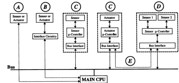
The different methods of connecting transducers to a main CPU are shown in Figure 3-2. The different methods are labeled with letters and increase in complexity from left to right. Method A shows a "dumb"2 transducer connected directly to the main CPU. Any A/D conversion or signal conditioning for the transducer is done centrally in the main CPU and is the method previously shown in Figure 3-1. Method B shows a dumb transducer connected to the main CPU through local circuitry-either A/D conversion or simple signal conditioning. This method begins to remove a portion of the data computation from the main CPU. Method C
2 As used here, a "dumb" transducer is any sensor or actuator which outputs only raw data-no computation of the data is done local to the transducer.
Chapter 3: Traditional Flight Control System Architectures
shows a "smart node"
3connected to the CPU via a data bus. The smart node will be discussed in
Chapter 4. Recall from the ULV case study in Chapter 1 that a data bus allows the different
sensors and actuators of a system to share the same transmission medium when communicating
with the CPU. The main point here is that a smart node includes three elements: a dumb
transducer, a local microcontroller for data calculations, and a bus interface which allows the
device to talk to the main CPU through the data bus. These are enclosed in the dashed line boxes
in Figure 3-2. Method D shows a multiple sensor smart node, connected to the main CPU via the
data bus. Finally, method E depicts what is known as peer-to-peer communication. This form of
communication allows transducer to transducer communication without involving the main CPU,
and is readily accomplished with the use of smart nodes.
Sensor or I
ActuaSensorSensor or
Sensor Actuaor or Sensor Actuator Sensor I Sensor 2Actuator ActuatorI a
Sensor Acuator Sensor -Contoller A- ontonerl a-Contoer
Interface Circuitry -Contorl
Figure 3-2: Interconnection of Transducers
After
initially analyzing traditional flight control system architectures and then
specifying the different methods of connecting transducers to a main CPU, new requirements for
an alternative flight control system can be defined. The term "new requirements" refers to a list
of desired characteristics for the alternative architecture. Many of these characteristics have
been mentioned previously, and they support the request for a scalable architecture made in
Chapter 2:
3
Pradip Madan, from Echelon Corporation, defines a "smart node" as any device integrating transducer
element and basic electronics for linearization, calibration, and communication [15].
* System modularity and upgrades
* Continuing expansion of system capability
* Easy troubleshooting of transducers-they can be tested off-board and more easily maintained using common test facilities
* Distributed processing as required
Recall that a body of technology exists and is in wide use to implement plug-and-play systems of sensors and actuators and meet these desired characteristics. It is known as the data bus. In order for a product to meet these requirements, it must possess an architecture which is different from many systems currently on the market. Direct processor interface designs in traditional architectures are difficult to modify and eventually become outdated. In order for a system to be modular, a plug-and-play simplicity with standard interfaces is desired, where different parts of the flight control system could be interchanged and have as little effect as possible on the entire system.. Chapter 4 will show that a data bus can meet all of these needs.
3.3 Initial Architectural
Conclusions
This chapter has tied together many ideas to form initial architectural conclusions. The stage was set with the requirements definition conclusion calling for a scalable architecture which preserved the prior design of the system, but also allowed for component improvements throughout the life of the vehicle. It was determined that the traditional centralized processing architecture could not easily allow for component improvements, and its direct processor interface design eventually led to an obsolete product after a short period of time. A plug-and-play capable system with standard interfaces is desired, and it was determined that the best way to implement this type of system is through a distributed architecture implementing a data bus. The next chapter will discuss the data bus, its overall characteristics, and existing data bus technology.
Chapter 4
The Data Bus
A data bus offers many benefits to engineers who must design and implement distributed architecture systems. This chapter will discuss the major characteristics of the data bus, its advantages over the point-to-point solution in a centralized architecture, and the issues surrounding the implementation of a distributed architecture using the data bus. In addition, existing data bus technologies will be discussed and comparisons between various busses will be made. The chapter will end with a description of two existing data busses.
4.1
Data Bus
Characteristics
A bus is a common set of electrical wires connecting a group of devices, such as sensors and actuators, in order to transfer data among them. Bus communication is not like that of point-to-point communication in traditional centralized architectures.
Unlike point-to-point connections, which allow only two devices to communicate by connecting the I/O ports of the first device with the I/O ports of the second device, a bus joins a larger number of devices and allows the exchange of data among all of them. In point-to-point communication, when two devices are connected to each other, they are usually free to send data back and forth when and how they like. On the other hand, bus communication requires a set of rules, known as the protocol, to let information flow from one device to another.
Information travelling over the bus has a digital format and is transferred serially in bits (zeros and ones) or bytes (eight bits). Serial communication has the advantage of only requiring a limited number of lines to transfer information. The serial interface requires only one signal wire to carry data in one direction and two wires to carry data simultaneously in two directions. Sometimes a bus might have a positive and a negative data line. If two data lines are run close together along the same path, it is likely that they will be subjected to the same noise. The purpose of positive and negative data lines is to subtract the one line containing the noise, from
Chapter 4: The Data Bus
the other line containing the signal and the noise, leaving the true signal. This process is referred to as common mode rejection of the noise.
In many cases, information sent across the bus will be seen by all devices connected to the bus. Each device is given a number or address which distinguishes it from other devices connected to the system. The address is attached to the packet of information containing the message data, and devices can read this address to determine which device the message is destined for.
The advantages previously mentioned give the data bus a flexible topology making it easy to add new devices to existing systems. One limitation of the data bus is bandwidth. The bandwidth of a data bus determines that maximum amount of information that can travel over the bus during a period of time. A device can be added to the data bus as long as the bandwidth requirement of the device does not exceed the maximum bandwidth of the bus.
4.1.1
Topology
The topology of a system is the structure or arrangement of the system's nodes in relation to each other on the data bus. Recall from Chapter 3 that a node was defined as the integration of a transducer, a microcontroller for data calculations, and a bus interface to allow the device to communicate over the bus. The topology of a system usually determines how data will flow throughout that system. When designing a system, an engineer must decide which topology best meets his or her needs. The most common topologies are the ring, the star, and the tree.
4.1.1.1
The Ring
As shown in Figure 4-1, a ring topology has all of its nodes connected in series around a "ring", allowing data to travel in only one direction around that ring. When the system is configured, each node is given an identifier or address which it uses to distinguish itself from other nodes connected to the system. When a node receives the signal, it extracts any information that was labeled with its address. Then, if it wants, it adds information and a destination address to the signal, and repeats the signal to the next node in the ring. There are limitations to the ring. The system cannot be extended while it is running simply because that would require breaking the ring. A single point failure also exists because if one node fails, the entire system will fail.
Figure 4-1: Ring Topology for a Data Bus
4.1.1.2
The Star
As shown in Figure 4-2, the star centers around a master or host node. Every node in the system is connected to that host and all communications must go through the host. This type of structure is generally considered a master-slave architecture. Nodes can be easily added to the system without interrupting the operation of the system. Also, the failure of one of the slave nodes does not crash the whole system. A single point failure still exists at the central node; if the central node fails, the entire system will fail. The star structure appears to be very similar to that of a centralized architecture. Recall from Chapter 3 that the transducers of a centralized architecture are wired directly into the central node making replacement and substitution of the transducers difficult. A star structure differs from the true centralized architecture in that each slave node is connected to the master node through a dedicated port or interface. Data bus interfaces will be discussed in Sub-section 4.1.2
Chapter 4: The Data Bus
4.1.1.3
The
Tree
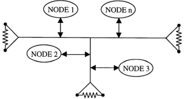
The tree structure is the most popular data bus topology. As shown in Figure 4-3, the tree consists of nodes branching off of the bus. The tree can be configured to allow communications in one of two modes. In one mode of communication, a node can be designated as the host node and the tree can operate in a master-slave protocol. In a different mode of communication, the nodes can talk among themselves through a peer-to-peer communication protocol. Peer-to-peer communication requires no intervention from a central controller. In either mode, the benign failure of one of the nodes will not crash the system. However, a node that might fail from broadcasting out of turn on the bus can cause a system crash. As shown in Figure 4-3, the tree topology requires terminating resistors at the ends of the bus. When a signal is sent over the bus, it will reach all of the nodes and then will reach the end of the bus. In many cases, because the signal cannot just disappear at the end of the bus, abrupt termination of the bus will cause a reflection of the signal and disturb communications. For that reason, the terminating resistors are placed at each end of the bus to absorb the signals and prevent reflections.
NODE 1 NODE n
Figure 4-3: Tree Topology for a Data Bus
4.1.2
Interfaces
While node topology determines the overall structure of the nodes on the bus, the interface determines how the nodes are physically attached to the bus. Generally, there are three types of interfaces for connecting transducers to a main controller or to each other: a custom interface, a standard interface, and a universal interface.
A custom interface is characteristic of the traditional centralized architecture and transducers are hardwired directly into their own specific port. To change a transducer would require unwiring the old transducer and wiring in the new transducer. This type of interface could not exist in a modular system.
With a standard interface, different ports are assigned to handle specific transducers. The different sensors and actuators are interfaced internally in their local region or node and then connected to these specific ports. For example, the system might have a "gyro port", an "accelerometer port", and a "GPS port". Every type of gyro, accelerometer, and GPS will have a standard interface which will allow the instrument to communicate through its port. Each port is given an address or identifier which remains the same throughout the life of the system. This allows a given port to be accessed at any time through its address. This type of interface adds more modularity to a system than a custom interface.
The universal interface gives a system the greatest degree of modularity. With a universal interface, all ports on the main controller or bus have the same interface and can handle all possible transducers. Where a gyro, accelerometer, and GPS would be connected to their own ports with a standard interface, a universal interface would allow the instruments to be connected to any port on the main controller or bus. When a node is attached to the system, a main controller will configure it and assign an address or identifier to its port so that software will know how to access the node.
An interface defines how nodes are connected to a data bus. The manner in which these nodes communicate will be defined next.
4.1.3
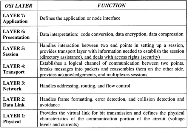
The OSI Model
The OSI (Open System Interconnection) model, developed by the ISO (International Standard Organization), is a framework for identifying the relationship of different functions in communication systems. Because many devices transfer data over the same communication medium, the bus access protocol must contain functions for handling situations that would not be encountered if the devices communicated in a point-to-point manner. Some typical functions include: data formatting and framing, addressing, routing, error and collision detection, and collision avoidance. Specifically, the OSI model defines seven layers of functions for communication systems. These layers and the functions performed by each layer are shown in Table 4-1 [3].