Dynamic Tailoring and Tuning for Space-Based
Precision Optical Structures
by
Rebecca Ann Masterson
Submitted to the Department of Mechanical Engineering in partial fulfillment of the requirements for the degree of
Doctor of Philosophy at the
MASSACHUSETTS INSTITUTE OF TECHNOLOGY February 2005
©
Rebecca Ann Masterson, MMV. All rights reserved. The author hereby grants to MIT permission to reproduce and distribute publicly paper and electronic copies of this thesis documentin whole or in part.
A uthor ...
Dop<tment of Fechanical Engineering September 30, 2004
Certified by ... ...
Warren P. Seering Professor of chanical Engineering T sis Committee Chairman Certified by...
e David W. Miller Associate Professor of Aero p"ics and Astronautics Thesis Supprisor Accepted by ...
Lallit Anand Chairman, Department Committee on Graduate Students
MASSACHUSETTS INSTrI'rE OF TECHNOLOGY
Dynamic Tailoring and Tuning for Space-Based Precision
Optical Structures
by
Rebecca Ann Masterson
Submitted to the Department of Mechanical Engineering on September 30, 2004, in partial fulfillment of the
requirements for the degree of Doctor of Philosophy
Abstract
Next-generation space telescopes in NASA's Origins missions require use of advanced imaging techniques to achieve high optical performance with limited launch mass. Structurally-connected Michelson interferometers meet these demands, but pose spe-cific challenges in the areas of system dynamics and controls, uncertainty management and testing. The telescope optics must meet stringent positional tolerances in the presence of environmental and on-board disturbances, resulting in heavy demands on structural dynamics and control. In addition, fully integrated system tests are cost-prohibitive due to the size and flexibility of the system coupled with the severe differences between the on-orbit and ground testing environments. As a result, the success of these missions relies heavily on the accuracy of the structural and control models used to predict system performance.
In this thesis, dynamic tailoring and tuning are applied to the design of precision optical space structures to meet aggressive performance requirements in the presence of parametric model uncertainty. Tailoring refers to changes made to the system dur-ing the design, and tundur-ing refers to adjustments on the physical hardware. Design optimizations aimed at improving both performance and robustness are considered for application to this problem. It is shown that when uncertainty is high and perfor-mance requirements are aggressive, existing robust design techniques do not always guarantee mission success. Therefore, dynamic tuning is considered to take advan-tage of the accuracy of hardware performance data to guide system adjustments to meet requirements. A range of hardware tuning techniques for practical implemen-tation are presented, and a hybrid model updating and tuning methodology using
isoperformance analysis is developed.
It is shown that dynamic tuning can enhance the performance of a system designed under high levels of uncertainty. Therefore, robust design is extended to include tuning elements that allow for uncertainty compensation after the structure is built. The new methodology, Robust Performance Tailoring for Tuning creates a design that is both robust to uncertainty and has significant tuning authority to allow for hardware adjustments. The design methodology is particularly well-suited for
high-performance, high-risk missions and improves existing levels of mission confidence in the absence of a fully integrated system test prior to launch. In the early stages of the mission the design is tailored for performance, robustness and tuning authority. The incorporation of carefully chosen tuning elements guarantees that, given an accurate uncertainty model, the physical structure is tunable so that system performance can be brought within requirements. It is shown that tailoring for tuning further extends the level of parametric uncertainty that can be tolerated at a given performance requirement beyond that of sequential tailoring and tuning, and is the only design methodology considered that is consistently successful for all simulated hardware realizations.
Thesis Committee Chairman: Warren P. Seering Title: Professor of Mechanical Engineering
Thesis Supervisor: David W. Miller
Acknowledgments
This work was supported by a Michelson Graduate Fellowship from the Jet Propulsion Laboratory and was performed at the MIT Space Systems Laboratory (SSL) under the direction of Professor David Miller.
I would like to thank all of the members of the MIT Space System Laboratory
for the friendship, support and knowledge that they have given to me during my six years as a graduate student. Marilyn Good, Sharon Leah Brown, and Paul Bauer provided their time and assistance in many areas. The members of the DOCS research group: Prof. Oli deWeck, Scott Uebelhart, Deborah Howell, Soon-Jo Chung, Dave Lobosco and Ryan Lim engaged in insightful discussions, made suggestions and did numerous little favors for me along the way. Scott and Dr. Ray Sedwick donated their computers so I could run long optimization problems. Dr. Carl Blaurock provided technical support for the DOCS toolbox and was always available for long discussions on physical parameter gradients. My officmates, Dr. Alice Liu, Simon Nolet and Alvar Saenz-Otero provided a pleasant work environment for me every day. They put up with my mood swings and engaged in useful discussions about tailoring and tuning, MATLAB, graphics and anything else that may have popped into my head in the course of the day. Alice was also my roommate and deserves special recognition for making sure I was fed and being a huge source of emotional support during some very stressful times.
I could not have finished this work without the support and encouragement of my
friends and family. Mark Hilstad, Steve Sell, and Karen Marias were always there for the lunches at Chicago Pizza, Wendy's and Rebecca's that kept me sane. Karen, thanks for all countless sanity breaks and puppet shows. I'm so glad that we have been able to travel this little PhD journey together. I owe a large debt of gratitude to Arthur Richards for his outstanding technical advice and personal support. Arthur spent a lot of time talking with me about the big picture and served as a sounding board for all of my ideas along the way. He pointed me to useful references, helped get me up to speed on optimization techniques and read the entire thesis, providing me with valuable feedback. In addition, I could always count on him for the daily crossword puzzle and peppermint patties. I also had the support and encouragement
of my parents, Robert and Donna Masterson, my brother, Eric Masterson and my fiance, Gordon Wong. Gordon's support went above and beyond all expectations. He radically changed his lifestyle by moving onto MIT campus from Back Bay while I
was finishing this thesis. He has been very patient with me through the entire thesis process and has never wavered in his support. Thank you Gordon, for helping me succeed and keeping me grounded.
I had the pleasure of working with a wonderful PhD committee. Dr. Allen
Bronow-icki from Northrup Grumman Space Technologies was a great source of information and has taught me much through his example. Prof George Barbastathis taught me optics so I could better understand the systems I was working on and provided discus-sions and support throughout the process. Prof. Warren Seering was my committee chair and served as my liaison to the mechanical engineering department. Warren
has supported me and my research since I was undergraduate, and I am very lucky to have wandered into his office seven years ago looking for a senior thesis topic. My research advisor, Prof. David Miller, has been a great source of technical guidance and support throughout my entire graduate career. He made my graduate experience very positive and has been an inspiration to me. I cannot thank him enough.
This thesis is dedicated to my parents, Robert and Donna Masterson and to my brother, Eric Masterson.
Contents
1 Introduction
1.1 Space-Based Interferometry . . . .
1.1.1 Astrometry and Imaging . . . . 1.1.2 Planet Detection . . . . 1.1.3 Technical Challenges . . . . 1.1.4 M issions . . . . 1.2 Problem Statement . . . . 1.2.1 Background . . . . 1.2.2 Approach . . . . 1.2.3 Research Objectives . . . . 1.3 Previous Work . . . . 1.4 Thesis Roadmap . . . . 2 Performance Tailoring 2.1 PT Formulation . . . . 2.2 SCI Development Model . . . .
2.3 PT Implementation . . . . 2.3.1 Performance Metric . . . .
2.3.2 Performance Gradients . . . .
2.3.3 Design Variables . . . . 2.3.4 Finite Element Gradients . . . .
2.3.5 Constraints . . . . 2.4 Optimization Algorithms . . . . 2.4.1 Sequential Quadratic Programming . . .
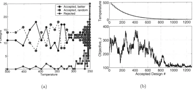
2.4.2 Simulated Annealing . . . .
2.5 Performance Tailoring Results . . . .
2.5.1 Comparison of Optimization Algorithms
2.5.2 Performance Tailored Design . . . .
2.6 Sum m ary . . . .
3 Robust Performance Tailoring
3.1 Uncertainty . . . .
3.1.1 Uncertainty Models . . . .
3.1.2 Uncertainty Analysis . . . .
3.1.3 Example: SCI Development Model . . .
19 . . 20 . . 20 . . 22 . . 23 . . 24 . . 25 . . 26 . . 29 . . 30 . . 31 . . 37 41 42 42 48 48 50 53 54 55 56 57 59 62 63 66 71 73 74 75 75 78
3.2 RPT Formulation ... ... 84
3.2.1 Anti-optimization . . . . 85
3.2.2 Multiple Model . . . . 87
3.2.3 Statistical Robustness Metric . . . . 88
3.3 RPT Designs . . . . 90
3.3.1 Algorithm comparisons . . . . 90
3.3.2 Objective function comparisons . . . . 95
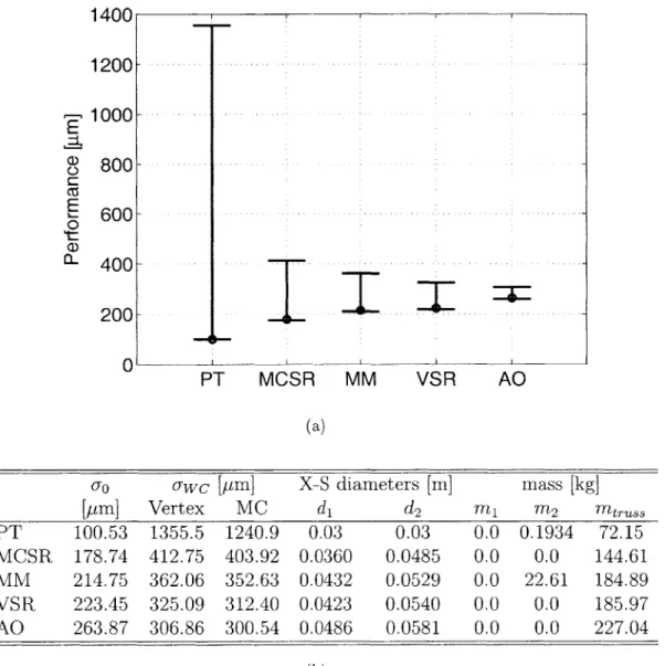
3.3.3 Comparison to PT design . . . . 98
3.4 Limitations: Design Regimes . . . . 104
3.5 Summary . . . . 107
4 Dynamic Tuning 109 4.1 Tuning Formulation . . . . 110
4.1.1 Example . . . . 112
4.1.2 Design Regimes . . . . 122
4.2 Tuning in Practical Application . . . . 124
4.2.1 Hardware-only Tuning . . . . 125
4.2.2 Model-only Tuning . . . . 129
4.2.3 Example . . . . 132
4.3 Isoperformance Updating for Tuning . . . . 136
4.3.1 Model Updating . . . . 138
4.3.2 Isoperformance . . . . 139
4.3.3 Tuning Algorithm . . . . 140
4.3.4 Examples . . . . 143
4.3.5 Comparison of Tuning Methods . . . . 148
4.4 Summary . . . . 150
5 Robust Performance Tailoring with Tuning 153 5.1 RPTT Formulation . . . . 154
5.2 SCI Development Model . . . . 158
5.2.1 Optimization Algorithms . . . . 159
5.2.2 Comparison to PT and RPT Designs . . . . 160
5.2.3 Design Regimes . . . . 167
5.3 RPTT Simulations . . . . 169
5.3.1 Tuning Authority . . . . 169
5.3.2 Hardware Simulations . . . . 171
5.4 Summary . . . . 179
6 Focus Application: Structurally Connected TPF 183 6.1 Model Description . . . . 183
6.1.1 Reaction Wheel Assembly Disturbances . . . . 185
6.1.2 Vibration Isolation . . . . 187
6.1.3 P lant . . . . 188
6.1.4 Attitude Control System . . . . 196
6.2.1 Tailoring . . . . 199 6.2.2 Tuning . . . . 201 6.2.3 Uncertainty . . . . 201 6.3 Optimization Implementation . . . . 202 6.4 Results . . . . 205 6.5 Summary . . . . 210
7 Conclusions and Recommendations 213 7.1 Thesis Summary . . . . 213
7.2 Contributions . . . . 217
7.3 Future Work . . . . 218
A Gradient-Based Optimization 221 A.1 Steepest Descent . . . . 222
A.1.1 Stepsize Selection . . . . 223
A.2 Newton's Method . . . . 224
A.3 Conjugate Gradient . . . . 225
List of Figures
1-1 Timeline of Origins missions. . . . .
1-2 Artists' concepts of SIM and TPF. . . . .
1-3 Current model validation and performance assessment approach.
2-1 2-2 2-3 2-4 2-5 2-6 2-7 2-8 3-1 3-2 3-3 3-4 3-5 3-6 3-7 3-8 3-9 3-10 3-11 3-12 4-1 4-2 4-3 4-4 4-5 4-6 4-7 4-8 4-9 4-10
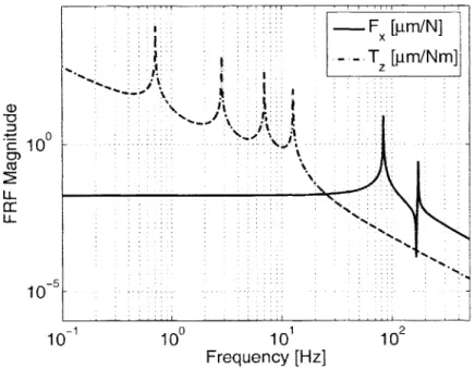
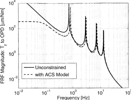
Schematic of SCI development model. . . . . Frequency response functions of SCI . . . . T, FRF of SCI: with and without ACS . . . . Simulated annealing algorithm. . . . . Development model generation algorithm. . . . . . Search results for PT with simulated annealing. . . Modal energy: nominal and PT designs . . . . Critical modes shapes for nominal and PT designs.
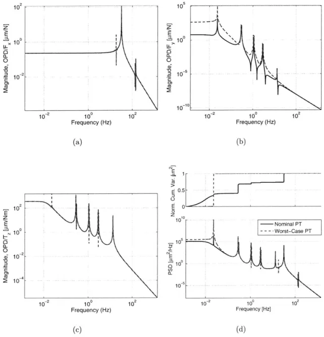
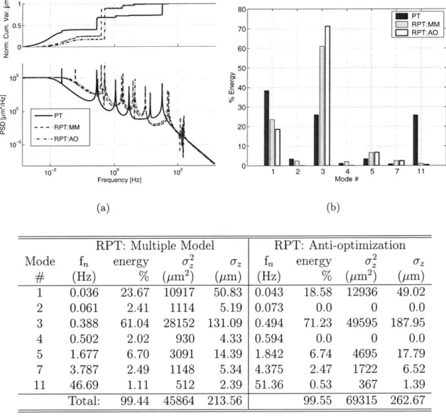
Uncertainty propagation on PT design. . . . . PT model with uncertainty: FRFs and PSDs. .
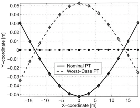
% Total energy by mode: PT with uncertainty. First bending mode: PT design with uncertainty. Performance vs. weighting: VSR RPT optimization.
Nominal and worst case performance for PT and RPT optimizations. Modal energy: PT and RPT designs with nominal uncertainty. . Critical mode shapes: PT and RPT designs, j= '5...
Modal energy: PT and RPT designs with worst-case uncertainty. Critical mode shapes: PT and RPT designs, ' = .
RMS OPD for PT and RPT designs vs A. . . . . Performance requirement vs uncertainty: PT and RPT designs. . . PT worst-case tuning results. . . . . RPT AO worst-case tuning results . . . .
Modal energy: tuned worst-case PT design. . . . .
Mode shape comparison: PT untuned and tuned. . . . . Modal energy: tuned worst-case RPT AO design. . . . . Mode shape comparison: RPT AO untuned and tuned. . . . . Requirement vs uncertainty for PT and RPT designs with tuning. . Barrier method implementation. . . . . M odel tuning results. . . . . Hardware tuning results. . . . .
20 25 27 . . . . 43 . . . . 47 . . . . 50 . . . . 60 . . . . 63 . . . . 65 . . . . 68 . . . . 70 . . . . 80 . . . . 81 . . . . 83 . . . . 84 . . . . 95 96 99 100 102 103 105 106 115 117 118 119 121 122 123 128 135 137
4-11 Isoperformance tuning algorithm. . . . . 141
4-12 Isoperformance tuning results on SCI model: pi = E1, P2 = E2.. .... 144
4-13 Isoperformance tuning results on SCI model: pi = El, P2 = P.... 147
5-1 Nominal, worst-case and tuned performance for all designs. . . . . 162
5-2 Modal energy: RPTT design. . . . . 164
5-3 Modal characteristics of first bending mode in all designs. . . . . 166
5-4 Performance requirement vs uncertainty: all designs. . . . . 168
5-5 RPTT design performance vs. weighting. . . . . 170
5-6 Hardware simulation algorithm. . . . . 172
5-7 Monte Carlo uncertainty space, A = 10%. . . . . 173
5-8 PT, RPT and RPTT Simulation results, A = 10%, -Zrq = 220pm . . 174
5-9 Monte Carlo uncertainty space, A = 21.5%. . . . . 176
5-10 PT, RPT and RPTT Simulation results, A = 21.5%, -Z,,q = 330pm. . 178 5-11 RPTT design performance vs. weighting. . . . . 180
6-1 Schematic of TPF SCI Model. . . . . 184
6-2 SCI TPF plant finite element model. . . . . 185
6-3 RWA disturbance model. . . . . 188
6-4 Transfer functions of Isolator models. . . . . 189
6-5 TPF SCI truss bay geometry. . . . . 191
6-6 Structural model schematic showing optical paths. . . . . 195
6-7 Output PSD and cumulative variance from nominal TPF SCI design. 197 6-8 Mode Shapes of nominal SCI TPF design. . . . . 198
6-9 Schematic of TPF SCI tailoring parameters. . . . . 200
6-10 Implementation flow for generating integrated TPF model. . . . . 204
6-11 SCI TPF PT design . . . . 207
6-12 SCI TPF RPT Design . . . . 207
6-13 SCI TPF RPTT Design . . . . 208
List of Tables
1.1 Effect of simulation results on mission. . . . . 1.2 Effect of simulation results on mission with tuning. . . . . . 2.1 2.2 2.3 2.4 2.5 2.6 3.1 3.2 3.3 3.4 3.5 4.1 4.2 4.3 4.4 4.5 4.6 . . 28 . . 30
Mass breakdown of SCI development model. . . . . 44
Natural frequencies and mode shapes of nominal SCI model . . . . . 45
Tailoring parameters for SCI sample problem. . . . . 53
PT optimization results, Jo = 471 gm. . . . . 63
SA algorithm parameters. . . . . 64
PT optimization: MC SQP optimizations. . . . . 66
Uncertainty parameters for SCI development model. . . . . 78
Uncertainty propagation results: PT design. . . . . 80
Algorithm performance: anti-optimization. . . . . 91
Algorithm performance: multiple model, Oi = 1/nv. . . . . 92
Algorithm performance: statistical robustness, a = 0.5. . . . . 93
Tuning parameters for SCI development model. . . . . 113
Tuning performance summary for PT and RPT designs. . . . . 113
Hardware Model Data. . . . . 133
Uncertainty parameters for SCI development model. . . . . 145
Hardware Model Data: Example 2. . . . . 146
Tuning results on fifty hardware simulations. . . . . 149
5.1 Algorithm performance: RPTT, a = 0.0, A = 0.1. . . . . 5.2 Performance and design parameters for optimal designs . . . . 5.3 Performance and parameters for tuned worst-case realizations. 160 161 161 RWA disturbance model parameters... TPF SCI model mass breakdown. . . . . Truss properties. . . . . Truss element and grid numbering. . . . . . Bus model elements and properties. . . . . . Primary mirror properties. . . . . Primary mirror mount properties. . . . . TPF SCI instrument elements. . . . . Critical modes of nominal TPF SCI design. . TPF SCI model tailoring parameters. . . . . . . . . 187 . . . . 190 . . . . 190 . . . . 191 . . . . 192 . . . . 193 . . . . 193 . . . . 194 . . . . 197 . . . . 199 6.1 6.2 6.3 6.4 6.5 6.6 6.7 6.8 6.9 6.10
6.11 TPF SCI model tuning parameters. . . . . 201
6.12 TPF SCI model uncertainty parameters. . . . . 202
6.13 Design parameters for nominal and optimal TPF SCI designs. . . . . 206
6.14 Performance predictions for all TPF SCI designs. . . . . 209 6.15 Tuning parameters for tuned worst-case TPF SCI realizations. . . . . 209
Nomenclature
Abbreviations
ACS attitude control system
AO anti-optimization
BSD barrier steepest descent
DOCS Disturbance Optics Controls Structures
CSJ control-structures interaction
CTE coefficient of thermal expansion
ESO European Southern Observatory FEM finite element model
FRF frequency response function
GSE governing sensitivity equation
HST Hubble Space Telescope
JPL Jet Propulsion Laboratory
JWST James Webb Space Telescope LOS line of sight
LQR lineaer quadratic regulator IR infrared
MC Monte Carlo
MM multiple model
MPC Model Predictive Control
MUF model uncertainty factor
NGST Next Generation Space Telescope OPD optical pathlength difference
PM primary mirror
PSD power spectral density PT Performance Tailoring
QP quadratic programming RMS root mean square
RPT Roubst Performance Tailoring
RPTT Robust Performance Tailoring for Tuning RWA reaction wheel assembly
simulated annealing
structurally-connected interferometer Space Interferometry Mission
system intergration test
sequential quadratic programming statistical robustness
Terrestrial Planet Finder Tailoring for Tuning ultra-low expansion worst-case Symbols Ai A, B, C B(-) B w B, Ci CZ5 Ei Fx , Fy, Tz G(.) H I K J L L M AC01i Mcomb P Piso T R Szz SYW X, Y, Z di cross-sectional area state-space matrices barrier function
disturbance input mapping matrix interferometric baseline
amplitude coefficient output mapping matrix Young's Moudulus
force and torque disturbances transfer function
Hessian
identity matrix, area moment of inertia finite element stiffness matrix
optimzation cost Langrangian length
finite element mass matrix collector mass
combiner mass total mass limit
uncertainty parameter space isoperformance set
temperature distance to star output PSD disturbance PSD coordinate system axes tuning parameter space cross-sectional diameter SA SCI SIM SIT SQP SR TPF TT ULE WC
dk f f() j(-), h() h hi kc, ka, kr, kT mni q S w z <b, q3
z
Eq cY a, /3 A I-k p C7optimization search direction frequency
performance function constraints
height
harmonic number
simulated annealing paramters design mass
uncertainty parameters modal degrees of freedom Laplace variable
white noise, width
physical degrees of freedom tailoring parameters
tuning paramters
output metric, dummy optimization cost uncertainty level
natural frequeny mode shapes
output covariance matrix state covariance matrix damping ratio
optimization step size optimization weights Lagrange multiplier barrier sequence Poisson's ratio material density
variance (mean square if zero mean) standard deviation (RMS if zero mean)
Subscripts and Superscripts
optimal solution
Hermitian (complex-conjugate tanspose) hardware value transpose worst-case value nominal value requirement tuned value (.)H (-)Hw (.)T OwC ()req ()X
Chapter 1
Introduction
Next-generation precision telescopes, such as space-based interferometers, push the
boundaries of existing design methodologies. In order to achieve science goals,
nanome-ter level pointing stability and precise wavefront control are necessary. These
require-ments place a large burden on the structural dynamics and control systems. In
ad-dition, fully-integrated system tests on interferometers are cost-prohibitive, placing a
heavy dependence on models and simulation for pre-launch performance assessment.
In effect, inherently uncertain models and approximations are relied upon to
pro-vide precise performance predictions. Traditional robust design techniques are not
adequate to guarantee success under such conditions.
To address this problem, a two-stage design methodology called Robust
Perfor-mance Tailoring for Tuning (RPTT) is developed. It is an extension to robust design
that includes, in the cost function, the concept of tunability . Uncertainty
compen-sation is shared between robust design and hardware tuning. RPTT is employed
during the design stage when uncertainty is high but the design parameter space is
large. Hardware tuning is used after the components are built, when the performance
is known, but only limited adjustments are possible. The methodology is developed
in the context of structurally-connected space-based interferometers such as NASA's
Space Interferometry Mission (SIM) and Terrestrial Planet Finder (TPF), but is also
applicable to other precision optical systems such as the James Webb Space Telescope
- 777 - -
--1.1
Space-Based Interferometry
NASA's Origins program is an on-going effort aimed at exploring both the nature of the universe and its inhabitants. The specific goals of the program are to answer questions about the origin of our universe and to search for other Earth-like plan-ets in nearby solar systems. The program consists of a family of missions that span over twenty years (Figure 1-1). The earliest telescopes, including the Hubble Space Telescope (HST), are in operation and provide valuable information to scientists and astronomers at the time of this writing. Upcoming missions include SIM, JWST, and TPF (interferometer and coronograph). All three of these missions have ambi-tious science goals that push the boundaries of engineering across many disciplines, including optics, structures and control.
Figure 1-1: Timeline of Origins missions [3].
1.1.1
Astrometry and Imaging
In order to achieve the first of Origins' goals, mapping the universe and exploring its origins, a telescope with very high angular resolution is necessary. Angular resolution
01ii
is an optical metric that describes the accuracy of an optical system. It is defined as the minimum resolvable angular separation between two objects [54]. Consider two objects located far from a telescope, but very close to each other. A low-angular resolution telescope is unable to resolve the two objects, and they appear to an observer as a single blurred object. A telescope with high angular resolution, however, presents an image of two distinct light sources.
One challenge faced in the design of these telescopes is the limitations imposed by a trade-off between system mass and optical performance. In the case of a monolithic telescope, such as HST, the angular resolution of the system scales proportionally with the diameter of the primary mirror. However, as the primary mirror becomes larger it also becomes more massive and more expensive to manufacture and launch. Therefore mass and cost budgets limit the angular resolution that can be achieved with a monolithic system.
One alternative to the monolithic telescope design that has generated much inter-est over the past few decades is astronomical interferometers [105, 8]. These instru-ments provide high resolution imaging and astrometry at a significant savings of mass and volume compared to a monolithic design. Interferometers function by combining the light gathered by two or more smaller apertures separated by a large baseline. The angular resolution of an interferometer increases proportionally to the length of this baseline. Therefore, it is not necessary to manufacture and launch very large mirrors. Instead, it is only necessary to place collecting mirrors sufficiently far away from each other to achieve the desired performance.
A number of ground-based stellar interferometers are currently in operation. These
include the Keck Observatory [29] on Mauna Kea in Hawaii, the Sydney University Stellar Interferometer [33, 34] (SUSI) in Australia, and the Navy Prototype Optical
Interferometer [9] (NPOI) in Flagstaff, Arizona. These systems have already provided valuable astronomical data [58, 59, 30, 38, 77, 32] such as stellar images, astromet-ric measurements of stellar positions and stellar angular diameters. However, the optical performance of these ground interferometers is limited by atmospheric distor-tions. The next logical step is to place these systems in space where they can operate
unfettered by the Earth's atmosphere [8].
1.1.2
Planet Detection
The second main goal of the Origins program is to search for life in other solar systems. This aim requires the detection and study of extra-solar, Earth-like planets. Currently, planet detection is done by ground-based telescopes that measure the motion of a star due to an orbiting planet. This technique has been successful in locating a number of Jupiter-sized planets, but is not sensitive enough to find smaller planets with mass comparable to that of the Earth. Therefore, the concept of a single instrument that detects Earth-like planets through their radiated heat and then performs a spectroscopic analysis to find signatures of carbon dioxide, water and ozone has been proposed [6].
There are two main challenges associated with this type of detection scheme. First, it is necessary to distinguish the radiated heat from that of the star. If the observing instrument is located on Earth, the heat from the planet is entirely swamped by the radiation from the Earth's atmosphere and the ambient temperature of the optical elements. However, even if the instrument is placed in space, removing these sources of noise, the contrast ratio of the star to the planet is on the order of 107. It is necessary, then, to find a way to separate the star radiation from that of the planet.
A second challenge arises due to the small angular separation between the planet and
the star. As discussed above, a high-angular resolution instrument is necessary to resolve the two sources.
A nulling interferometer operating in the infrared (IR) has been proposed as
the solution to the planet detection problem. The concept was first introduced by Bracewell [20]. He and his colleagues suggested using an interferometer to destruc-tively interfere star radiation captured by two apertures separated by a baseline [21]. The destructive interference results in the cancellation of the stellar flux over a broad waveband. If the instrument is designed correctly, the planet emission, which is slightly off-axis from the star, constructively interferes and is reinforced allowing the detection of the planet despite the stronger stellar radiation. Designs for nulling IR
interferometers have been proposed by Leger et al. [71], Mennesson and Mariotti [86] and Angel and Woolf [6].
1.1.3
Technical Challenges
While interferometers do provide solutions to the astrometry and planet detection problems, they also pose a significant set of engineering challenges. In order to pro-duce astrometric measurements, images or to achieve nulling, the interferometers must be able to acquire fringes. Interferometric fringes are the dark and light zones that result from the interference of two light sources (see [54] for a full discussion on interferometry). The acquisition of fringes is possible given that the distances the light travels through the two sides of the interferometer are equal to within a fraction of a wavelength. This optical metric is known as the optical path difference (OPD).
Recall that the angular resolution of the system scales with the baseline. Large baseline can be achieved by placing the collecting and combining optics on a deploy-able or articulating truss structure or by flying them on individual spacecraft. The first configuration is known as a structurally-connected interferometer (SCI), while the latter is called a formation flown interferometer or a separated spacecraft interfer-ometer [72]. A high-resolution interferinterfer-ometer operating in the visible regime requires that the light paths be equal to within a few nanometers over a baseline of ten or one hundred meters. In the case of the SCI architecture, flexibility in the support-ing structure and the presence of on-board disturbances place a large demand on the structural dynamics and control systems to achieve the required stability. The formation flown problem is also difficult, but its challenge lies in the knowledge of position and the control of the spacecraft formation. The work included in this thesis is focused on the SCI architecture.
A second area of difficulty associated with space-based interferometers is system
integration and test. A full system integration test (SIT) previous to launch is not practical due to the large contrast between the ground testing and operations environ-ments. The system is designed for operation in a vacuous, zero-gravity environment, but a ground test is influenced by gravity and atmospheric distortions. In the case of
the SCI, both the size and flexibility of the structure cause difficulties when creating a testing environment on Earth that is consistent with the operations environment in space. More importantly, a pseudo-star is necessary to inject collimated light across the entire baseline of the interferometer simulating the observation of a star many light years away. A pseudo-star of this type is currently used with the Microarecond Metrology Testbed which is a technology demonstrator for the Space Interferometry Mission [69]. In this case, only one pseudo-star is necessary to test the single baseline interferometer. However, to complete the objectives of the Origins missions a mul-tiple baseline interferometer is necessary. Therefore, one pseudo-star per baseline is required to test all baselines simultaneously. In addition, each pseudo-star must be more sensitive than the interferometer instrument that it is designed to test. Such a
SIT is theoretically possible, but is cost-prohibitive.
1.1.4 Missions
The Space Interferometry Mission (SIM) is the first interferometer in the suite of Ori-gins missions and is scheduled for launch in 2009 . The primary goal of SIM is planet detection and galaxy mapping through precision astrometric measurements. SIM is also a technology demonstrator for space-based interferometry and hopes to pave the way for future Origins missions. The current SIM design, shown in Figure 1-2(a) [13, is a structurally-connected Michelson interferometer with four individual parallel base-lines. Each baseline is approximately 10 meters long and consists of 35 cm diameter aperture telescopes that collect star light, compress it and direct it through the opti-cal train to the beam combiner. Two of the interferometers are guide interferometers and are pointed directly at guide stars to provide precise inertial reference data. The other two interferometers are science instruments and are used for observing science targets [693.
The Terrestrial Planet Finder
(TPF)
is a second generation Origins mission sched-uled for launch between 2012-2015. The science goals of the mission include detecting Earth-like planets in a habitable zone around nearby stars, searching for atmospheric signatures of life through spectroscopy and performing high-resolution imaging of(a) (b)
Figure 1-2: Artists' concepts of Origins missions: (a) SIM [1] and (b) TPF [2].
astrophysical targets [2, 70]. The original baseline design for TPF is an infrared sep-arated spacecraft interferometer [13]. However, as the result of a series of industry studies at the time of this writing there are three competing architectures for TPF: an infrared (IR) structurally-connected interferometer, an infrared formation-flown interferometer and a visible light coronograph. Figure 1-2(b) shows an artist's con-cept of the SCI design proposed by Lockheed Martin. For the purpose of the work in this thesis only the SCI architecture is considered.
1.2
Problem Statement
One problem inherent in complex system design arises due to a trade-off that occurs over the development phase between design flexibility and the accuracy of performance predictions. Early in the mission development, models of the proposed design are created to assess system performance. At this stage, design alterations come at a modest cost, but the models used to predict performance are uncertain, resulting in low-confidence predictions. Designing the system to meet requirements across this large uncertainty space may not be possible. In the later phases of the program, flight components and limited integrated test data become available dramatically increasing the accuracy of the performance predictions. However, an unfortunate consequence
may be that it becomes certain that the system will fail. Design changes at this stage are quite expensive now that flight hardware is built.
Space-based, structurally-connected interferometers are particularly affected by this trade since they are classified as both high-performance and high-risk systems. The precision optical performance required for astrometry, nulling and imaging cou-pled with the size and flexibility of the instrument place heavy demand on the struc-tural dynamics and control systems, while the high cost of a fully-integrated system test limits the ability to guarantee desired on-orbit performance prior to launch. As a result, it is necessary to design the system very precisely, yet rely heavily on models and simulations, which are approximations, to predict performance.
1.2.1
Background
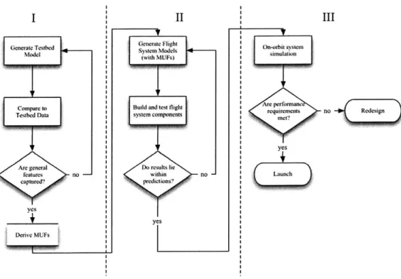
One approach to the design of these systems is shown in Figure 1-3. The figure is broken up into three different regions. In Region I, testbeds are used to validate modeling techniques and generate model uncertainty factors (MUFs) [18]. Testbed models are developed and performance predictions from these models are compared to data from the testbeds. The models are refined until all of the major features visible in the testbed data are captured in the model. Then MUFs are chosen to approximate any remaining differences between the model and the data that are difficult to quantify. Model predictions that have been adjusted by MUFs should be conservative when compared to the testbed data.
In Region II, the component models are used to predict performance and drive system design. The component developers deliver models of their respective designs. The MUFs are applied to the component models aid they are integrated to evalu-ate system performance. The component designs and associevalu-ated models are iterevalu-ated upon until the predicted system performance meets requirements. Once the designs are validated in this way, the developers build and deliver the flight system compo-nents. Upon delivery, the components are tested and compared with the conservative component models before acceptance. If the test data lies within the model predic-tions the models are considered validated, and the components are accepted.
Generate Tesdihd MOMd Amc generm features no -yes t id? ... .. U . II System ModekI, (with MUMs)
Buil and lest flight
Do results le , within . no -predctions f> yes I III on-orbit system re".irompts~ no yes
CLaunch
Figure 1-3: Current model validation and performance assessment approach.
In Region III, the test data from the component hardware is combined with an on-orbit simulation to predict system performance in the operational environment. The predictions are compared to the limited system validation test data that is available as well as to the requirements. Component interface uncertainty becomes relevant in this step since a blend of models and data are used in the simulation. If the simulation prediction meets requirements and the validation tests match predictions, the system is launched. If the simulation does not meet requirements, launch is delayed to allow for redesign and adjustments.
Four mission scenarios that could arise based on the process described above are listed in Table 1.1. In the first scenario, the simulation predictions meet performance, the system is launched and the on-orbit performance matches the predictions resulting in a successful mission. In the second scenario, the simulation predicts adequate per-formance, but the predictions are incorrect and on-orbit performance is not adequate leading to mission failure. In the third scenario, the predictions are incorrect again, but this time the simulation predicts poor performance while the on-orbit behavior would have been adequate, and the result is an unnecessary delay in launch. Finally,
Table 1.1: Effect of simulation results on mission.
#
Simulation Action On-Orbit ResultPrediction Performance
1 good launch good success
2 good launch bad failure
3 bad no launch good delay
4 bad no launch bad delay
in the fourth scenario, the simulation correctly predicts poor performance and the resulting launch delay and redesign is the appropriate action.
It is interesting to note that only the first scenario results in a successful mis-sion. All other scenarios lead to failure or a delay in launch. The fourth scenario is appropriate given the conditions and may eventually lead to success as long as the simulation predictions continue to be correct after adjustments and redesign. In the second and third scenarios the simulations predict the system operation incorrectly. As a result, scenario two is a complete failure, while scenario three calls for unnec-essary redesign that may lead to scenario two upon eventual launch. The simulation prediction is therefore a single-point failure in this approach.
One way to increase the chances of mission success is to ensure that the simulation predictions are always correct. Accomplishing this goal requires a large investment in modeling and analysis. Uncertainty modeling, structural optimization and robust design are all known techniques that are frequently employed to increase the accuracy of performance predictions. Uncertainty modeling involves identifying the sources of model uncertainty, quantifying them and producing bounds on performance predic-tions. Uncertainty models are combined with structural optimization in the field of robust design to find a design that meets the desired performance requirements and is insensitive to model uncertainties. However, it is well known in the field of robust control that robustness is achieved at the expense of nominal performance, and so, as a result, these tools alone may not be adequate for a system that must meet aggres-sive performance requirements under a high level of uncertainty. In this thesis, the problem of how to extend robust design techniques to ensure that stringent
perfor-mance requirements are met on-orbit when high-uncertainty models and simulations are depended upon for launch decisions is addressed.
1.2.2
Approach
The approach taken in this thesis is a formal synthesis of robust structural design and hardware tuning. The burden of uncertainty management is shared by both simulation and hardware. Instead of mitigating uncertainty through robust design or excessive modeling and component prototyping, it is managed by optimizing for a mix of performance, robustness and tunability. Such a scheme addresses the prob-lem of performance prediction accuracy vs. design flexibility by choosing parameters that can be tuned during component testing, system integration, or on-orbit, to af-fect the system performance thereby increasing hardware design flexibility. If the system is designed such that these parameters have enough authority to guarantee that performance requirements can be met regardless of where the actual system lies in the uncertainty space, then the resulting system is significantly more likely to be successful.
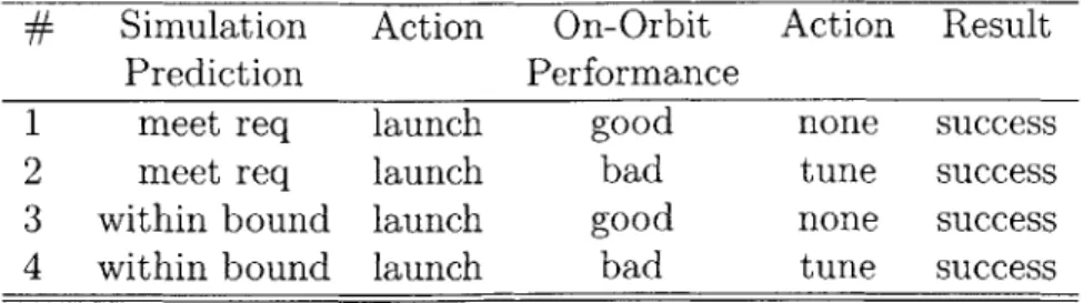
Consider the effect of such a design methodology on the scenarios in Table 1.1. The simulations are augmented with a formal pre-launch and on-orbit tuning pro-cess so that the predictions only need to meet performance within specified error bounds. If the system is guaranteed to be "tunable" within these bounds then the
scenarios are as shown in Table 1.2. The simulation prediction metric has changed from "good" or "bad" to "meet requirement" or "within bound." This distinction is made because if the prediction does not meet requirements, but is within the tunable range then launch is still the correct action. Note that all four situations lead to launch and mission success. The dependence on simulation is reduced by allowing for on-orbit adjustments and the requirements for launch are relaxed to allow for model uncertainty resulting in a greater probability of mission success.
When discussing the design methodology throughout the thesis the following ter-minology is used. The term Performance Tailoring (PT) describes the process of structural design for performance only, i.e. structural optimization without
consid-Table 1.2: Effect of
#
Simulation Prediction 1 meet req 2 meet req 3 within bound 4 within boundsimulation results on mission with tuning. Action On-Orbit Action Result
Performance
launch good none success
launch bad tune success
launch good none success
launch bad tune success
eration of model uncertainty. Robust Performance Tailoring (RPT) refers to robust structural optimization in which robustness to a specified uncertainty model is in-cluded in the design objective. Robust Performance Tailoring for Tuning (RPTT) is an extension to RPT in which a design is optimized for performance, robustness and tunability. In this approach the tuning or adjustment on hardware is anticipated and explicitly planned for during the design optimization.
1.2.3
Research Objectives
The main objective of this thesis is to develop a design methodology that is appropri-ate for high-performance and high-risk systems such as space-based interferometers. Available robust design tools are applied to this problem and evaluated for effective-ness. An extension to robust design that includes a formal tuning methodology is developed. The specific research goals, and thesis chapters in which they are ad-dressed, are as follows:
" Apply structural optimization and the robust design framework and tools to
space-based interferometer design. Identify control and noise parameters rele-vant to the design of precision structures for optical space systems [Chapters 2 and 3].
" Evaluate the performance of robust design techniques on high-performance and
high-uncertainty systems [Chapter 3].
" Formalize an efficient tuning methodology that can be applied to flight
performance within requirements [Chapter 4].
" Extend robust design techniques to include tailoring for tuning. Define the concept of tunability and incorporate the idea into robust optimization resulting in a formal relationship between structural tailoring and tuning [Chapter 5].
" Demonstrate through simulation that RPTT guarantees that the desired
per-formance can be achieved given an accurate model of parametric uncertainty [Chapter 5].
" Apply the RPTT design methodology to an integrated model of a precision
optical space structure. Choose appropriate tailoring and tuning parameters for the focus application [Chapter 6].
1.3
Previous Work
The research presented in this thesis draws from previous work in systems engineering, structural dynamics, integrated modeling, optimization and robust design. In this section a review of the relevant work in these fields is presented.
Structural optimization is a well-developed field with a rich history. The advent of the digital computer made optimizing structural elements in the design process practical. Numerous examples can be found in the literature of sizing, shape and topology optimization [64]. Sizing optimization is typically applied to a truss structure and uses parameters such as member cross-sectional area and plate thickness as design variables. In shape optimization the topology is fixed, but the structural boundaries are allowed to change [56]. In topology optimization much less is known about the structure and the search is for optimal material distributions to yield a preliminary structural configuration [114, 73].
A large body of work exists on the application of sizing optimization to truss
prob-lems to minimize mass subject to static constraints such as maximum stress. Many different optimization techniques have been applied to variations of this problem. The reader is referred to Kirsch [66] for an overview of gradient methods and examples. It
has been found that structural design problems tend to have many variables, include nonlinearities in the cost functions and/or constraints, and may be non-convex. As a result, non-gradient or heuristic, search techniques have become popular in recent years. Lagaros et al. apply genetic algorithms to the minimum weight sizing problem and compare the results to those obtained with gradient methods [67]. Hasancebi et al. use simulated annealing to determine the optimal size, shape and layout for minimum weight truss structures subject to stress, stability and displacement con-straints [51]. Manoharan and Shammuganathan provide a comparison of four search techniques, Tabu search, simulated annealing, genetic algorithms and branch-and-bound, applied to the truss sizing problem [79].
Structural optimization has also received a large amount of attention from the vibration suppression community. Yamakawa formulated the problem of minimum root mean square (RMS) tip displacement for a cantilevered beam and truss frame structures with deterministic loading [113] . Chen, Bruno and Salama demonstrated increased finite-time energy dissipation through combinatorial optimization of passive and active damping locations in a simulated annealing framework [26]. Langley uses a Quasi-Newton optimization algorithm to minimize kinetic energy and maximum strain in a near-periodic beam system by varying bay lengths and loss factors [68]. Keane, Nair and their colleagues at South Hampton University have done extensive work in vibration minimization through unusual truss geometries. They use genetic and evolutionary algorithms to design trusses that exploit the intrinsic vibration filtering capabilities of non-periodic structures to achieve passive isolation [63, 95,
96]. As a continuation of this work, Moshrefi-Torbati and Keane have published
the first experimental validation of topology optimization for passive isolation [91]. The authors built the optimized structure and demonstrated significant vibration suppression over the traditional design.
As the science requirements for telescope missions became move aggressive the structural vibration and control communities began to examine the idea of consid-ering structure and control design in parallel as an alternative to traditional design methods. Historically, designs are driven by mass and static requirements. The
struc-tural dynamics are analyzed after an architecture is chosen and detailed design has begun. The dynamics are then characterized and active control is implemented to compensate for undesirable behavior. The high-performance required by space-based
interferometers highlighted the need for a new approach. It was believed that exe-cuting the system design sequentially would not guarantee the high levels of stability necessary for mission success. The need for high control bandwidth to acheive high performance coupled with the detrimental effects from the interaction between this control and flexible dynamics led to the field of control-structures interaction.
There are many contributions in the field of combined control/structures design. For example, von Flotow shows that a truss structure can be optimized, or tailored, to generate a design that is more easily controlled [111]. Other authors include control in the optimization by adding control energy to the cost functional
[87]
or optimizing over closed-loop, instead of open-loop, performance [90, 14]. Uchida and Onoda extend the problem by considering the optimal design of passive damping for performance improvement on space structures. They optimize structural parameters and linear quadratic regulator (LQR) gains to minimize both mass and control effort [109]. In a more recent publication, Anthony and Elliott compare combined structure and control optimization strategies to individual optimizations [7]. Genetic algorithms are used to perform combinatorial optimization of joint and actuator locations to reduce the average vibrational energy in a given frequency band. It is shown that the combined optimization solution achieves greater attenuation then the sequential solutions.Crawley, Masters and Hyde formalize the CSI ideas by developing a methodology to unify structural dynamics and controls analysis to provide end-to-end design eval-uations for high performance structures. They stress the importance of considering both structure and control during conceptual design [31]. These ideas of concep-tual design are applied to a model of a stellar interferometer precision structure [81] and validated on a scaled experiment [82]. The experimental validation joins that of reference [91] as one of the few published in this area.
Application of these methodologies to precision telescopes led to the inclusion of optical performance in the models. Bronowicki optimized the truss member sizes of a
precision telescope structure for mass and optical performance metrics such as line of sight and wavefront error
[22].
Similar efforts have been made by JPL using structural and optical modeling tools developed in-house. Milman, Salama, and Wette optimized truss member areas and control gains to generate a Pareto optimal set of designs that minimize optical performance, control effort and system mass[89].
Combinatorial optimization of passive damper locations on an interferometer truss to minimize RMS OPD is presented by Joshi, Milman and Melody [62].As a result of this multidisciplinary approach to design and performance assess-ment the field of integrated modeling has been developed. An integrated model is a system design tool that includes the effects of cross-disciplinary sub-systems. The MIT Space Systems Laboratory, the Jet Propulsion Laboratory, NASA Goddard Space Flight Center and Ball Aerospace have demonstrated the role of integrated models in performance analysis and design of precision space telescopes. Mosier et al. use an integrated model of the Next-Generation Space Telescope (NGST) to trade line of sight (LOS) pointing error against reaction wheel speed and isolation corner frequency [92]. Miller and de Weck present the DOCS (disturbance-structures-optics-controls) integrated modeling environment and apply it to models of NEXUS and
NGST [35, 88]. Manil and Leiber apply Ball Aerospace integrated modeling tools to
a ground telescope proposed by the European Southern Observatory (ESO) [78]. The integrated telescope model includes structural and optical dynamics, active mirror control and environmental effects. Other examples of Ball implementation include application to a TPF coronograph model [74, 75]. At JPL the integrated modeling efforts are focused on SIM [49] and include attempts to validate the methodology on an interferometer testbed [85, 84].
The combination of structural optimization and integrated modeling may lead to high-performance designs, but if the models that are used in the optimization are not accurate the system that is ultimately built is not guaranteed to perform as predicted. Historically models have been used to help engineers understand the physical behavior of their system. Models are built of a piece of hardware and then predictions are compared to test data and model updating techniques are employed
to bring the two into agreement. In this sense, the models are simply used to verify reality. However, recent trends in complex structures require models to serve as predictors of future behavior. Since models, by definition, are only approximations to reality, there is considerable risk and uncertainty involved in the prediction process. The field of uncertainty and stochastic modeling is growing rapidly. Researchers are working to understand the sources of model uncertainty, develop models of it and propagate the effects of this uncertainty to provide bounds, or statistics, on the performance predictions.
There are many sources of possible model uncertainty, including global modeling, or model structure errors, parametric errors, discretization errors and environmental discrepancies [23, 27, 12, 93]. However, of these, parametric uncertainty is treated most often in the literature as it is the easiest to model and the most difficult to reduce due to lack of sufficient experimental data. There are several forms of uncertainty models with probabilistic models being the most popular. Simonian has compiled a database of measured damping data from twenty-three satellites [106]. He applies statistical models built from this data to an electro-optic jitter problem to obtain the probability density function of the performance, optical pointing error. Hasselman has also been a contributer in this area. He uses a generic modeling database derived from prior analysis and testing to generate uncertainty models for modal mass, damping and stiffness parameters [53, 52]. He compares the use of linear covariance, interval prediction and Monte Carlo propagation of the uncertainties through the analysis to obtain statistical bounds on frequency response functions.
A short-coming of statistical models is that often the data used to build the
un-certainty model is insufficient. Furthermore, the data that does exist originates from diverse structural systems making the application to a particular system, such as an interferometer, suspect. In this sense, the uncertainty model itself is uncertain. Ben-Haim and Elisakoff present an alternative to probabilistic models in their monograph on convex uncertainty modeling [15, 41]. The authors suggest that the performance predictions obtained through statistical analysis are quite sensitive to the distribution chosen for the uncertainty model. Therefore, convex, or bounded, models present an
attractive, and more conservative alternative, when there is insufficient data to build an accurate statistical model of parametric uncertainty. When these models are used in uncertainty propagation, bounds on the response are obtained in lieu of statistical output distributions.
These uncertainty models and propagation techniques are ultimately combined with structural optimization to produce designs that can meet performance require-ments despite the model uncertainty. This practice is known as robust design and has been popular among control experts for some time [110, 10, 47, 48]. Robust design optimization is a relatively new field in structural design, but has generated a lot of interest due to the rising complexity of systems
[40].
Anderson considers the problem of robust actuator and damping placement for structural control using a model with known errors [5]. Park, Hwang and Lee use Taguchi methods to post-process gradient-based structural optimization to find discrete sizing variables [99]. The Taguchi method [107, 102] is a quality-control technique originally developed for circuit design that has recently found application in structural optimization. In a later paper, Park et al. apply the Taguchi method to unconstrained structural op-timization to find robust optimal designs of three and ten-bar trusses subjected to applied loads [100]. The areas of the truss members are optimized with conventional methods first to minimize mass and then with the Taguchi method to minimize the sensitivity of the displacement of a given node to variations in the member areas. Constrained robust structural optimization problems are considered as well. Sand-gren and Cameron suggest a two-stage hybrid approach that combines the use of genetic algorithms for topology optimization with Monte Carlo uncertainty propa-gation to determine the statistics of the objective function and/or constraints [103]. The method is computationally expensive, but is successfully applied to a ten-bar truss problem and a higher-fidelity automobile inner panel using probabilistic mod-els of uncertainty. Elishakoff, Haftka and Fang use convex uncertainty modmod-els to perform "anti-optimization" or min-max style robust design [42]. They demonstrate their technique on a ten-bar truss problem subjected to uncertain loading as well as stress and displacement constraints.Although structural optimization and integrated modeling do much to enable the design of complex structures like space-based interferometers there is a lack of ap-plication of robust design to this problem in the literature. Structural optimization has been applied to the opto-mechanical jitter problem presented by interferome-ters, but robust design techniques have not. Instead, the robust design literature is generally concerned with truss-sizing problems for mass minimization or static dis-placement reduction and not with dynamic cost functions such as optical path jitter.
If space-based interferometers are to be designed and launched based on simulation
predictions alone, model uncertainty must be considered during the design process. However, in order to achieve robustness, a system sacrifices nominal performance. Therefore, robust design techniques reach their limitation when performance require-ments are aggressive and uncertainty is high. In this thesis both the application of robust optimization to SCI design and a technique that can be applied to problems that lie beyond the limits of robust design are presented.
1.4
Thesis Roadmap
A design methodology that extends robust design techniques for application to
high-performance, high-risk systems such as space-based interferometers is developed. In this chapter, background information on space-based interferometry is presented and motivates the need for an extension of current design techniques. A review of relevant literature is included.
In Chapter 2, Performance Tailoring, or the optimization of a structure to min-imize performance variance alone, is discussed. A simple model of a structurally-connected interferometer, referred to throughout as the development model, is in-troduced and discussed in detail. Included in the model are the structure, optical performance, and disturbance sources. The performance metric is RMS OPD, and methods for obtaining its gradient with respect to the design parameters are dis-cussed. In addition, an overview of two popular optimization methods, sequential quadratic programming and simulated annealing, is given. These algorithms are used