THE DYNAMICS OF UNSTEADY STRAIT AND STILL FLOW
Lawrence J. Pratt
B.S., University of Wisconsin (1975) M.S., University of Wisconsin (1977)
Submitted in Partial Fulfillment of the Requirements for the Degree of
DOCTOR OF PHILOSOPHY
at the
Massachusetts Institute of Technology and the
Woods Hole Oceanographic Institution April, 1982
Signature of Author
Certified by
Accepted by
Joint Program In Oceanogr phy, Massachusetts Institute of Technology - Woods Hole Oceano-graphic Institution, April, 1982.
thesis Supervisor UL)
Cha ;an,'Joint Committee for Physical Oc nography, Massachusetts Institute of Technology - Woods Hole Oceanographic
Institution.
LnGre
The Dynamics of Unsteady Strait and Sill Flow by
Lawrence J. Pratt
Submitted to the Massachusetts Institute of Technology, Woods Hole Oceanographic Institution Joint Program in Oceanography on April 30, 1982, in partial fulfillment of the requirements for the Degree of Doctor of Philosophy.
Abstract
The dynamics of steady and unsteady channel flow over large obstacles is studied analytically and numerically in an attempt to determine the applicability of classical hydraulic concepts to such flows. The study is motivated by a need to understand the influence of deep ocean straits and sills on the abyssal circulation.
Three types of channel flow are considered: nonrotating one dimensional (Chapter 2); semigeostrophic, constant potential vorticity (Chapter 3); and dispersive, zero potential vorticity (Chapter 4). In each case the discussion centers around the time-dependent adjustment
that occurs as a result of sudden obtrusion of an obstacle into a uniform initial flow or the oscillatory upstream forcing of a steady flow over topography.
For nondispersive (nonrotating or semigeostrophic) flow, nonlinear adjustment to obstacle obtrusion is examined using a characteristic formulation and numerical results obtained from a Lax-Wendroff scheme.
ii.
The adjustment process and asymptotic state are found to depend upon the height of the obstacle b0 in relation to a critical height bc and a blocking height bb. For b0 < bc < bb, isolated packets of
nondispersive (long gravity or Kelvin) waves are generated which propagate away from the obstacle, leaving the far field unaffected. For
bc < b0 < bb, a bore is generated which moves upstream and partially blocks the flow. In the semigeostrophic case, the potential vorticity of the flow is changed by the bore at a rate proportional to the differential rate of energy dissipation along the line of breakage. For bb < b0
the flow is completely blocked.
Dispersive results in the parameter range b0 < bc are obtained from a linear model of the adjustment that results from obstacle obtrusion into a uniform, rotating-channel flow. The results depend on the initial Froude number Fd (based on the Kelvin wave speed). The dispersive modes set up a decaying response about the obstacle if Fd < 1 and (possibly resonant) lee waves if Fd > 1. However, the far-field upstream response is found to depend on the behavior of the nondispersive Kelvin modes and is therefore nil.
Nonlinear steady solutions to nondispersive flow are obtained through direct integration of the equations of motion. The characteristic
formulation is used to evaluate the stability of various steady solutions with respect to small disturbances. Of the four types of steady solution,
the one in which hydraulic control occurs is found to be the most stable. This is verified by numerical experiments in which the steady, controlled
iii.
complicated (contains more than sill, say), then controlled flows may become destabilized and oscillations may be excited near the topography.
The transmission across the obstacle of energy associated with
upstrean-forced oscillations is studied using a reflection theory for small amplitude waves. The theory assumes quasi-steady flow over the obstacle and is accurate for waves long compared to the obstacle. For nonrotating flow, the reflection coefficients are bounded below by a value of 1/3. For semigeostrophic flow, however, the reflection coefficient can be arbitrarily small for large values of potential vorticity. This is explained as a result of the boundary-layer character of the
lv.
ACKNOWLEDGEMENTS
I wish to thank Nelson Hogg, my advisor and friend, for his patient guidance and support throughout the development of the thesis. I also wish to give special thanks to Joseph Pedlosky for his encouragement and
criticism during my days at Woods Hole and Chicago. I am also indebted to thesis committee members Erik Mollo-Christensen, Jack Whitehead, and Glen Flierl for their useful suggestions during preparation of the thesis, and to Mary Ann Lucas and Karin Bohr for help in preparing the manuscript.
Finally, I would like to thank Mindy for putting up with me during the final month before the defense.
TABLE OF CONTENTS
Page
Abstract ... i
Acknowledgements ... iv
Chapter 1 Introduction ... 1
Chapter 2 The Unsteady Hydraulics of Nonrotating flow ... 6
2.1 Background and Equations ... 6
2.2 Weak Solutions ... 10
2.3 Adjustment of a Steady Flow to Small Disturbances .... 12
2.4 Upstream Influence in Quasi-linear Hyperbolic Systems.. 18
2.5 Establishment of Steady Solutions ... 22
2.6 Unsteady Flow ... 27
2.7 Disruption of Control ... 31
2.8 Semi-steady Flow ... -... 35
2.9 Summary ... 38
Chapter 3 Unsteady Semigeostrophic Hydraulics ... 40
3.1 The Model ... 40
3.2 The Semigeostrophic Limit ... 41
3.3 Characteristics and Riemann Functions ... 44
3.4 Steady Solutions ... - ... 46
3.5 The Location of the Critical Point and Multiple Bifuractions ...-- - - ... 48
vi. 3.6 3.7 3.8 3.9 3.10 3.11 Chapter 4 4.1 4.2 Chapter 5 Appendices A B C References
Establishment of Steady Solutions ... Free-surface Shocks ... The Change in Potential Vorticity Across a Shock Total Blockage of the Obstacle ... Kelvin Wave Reflection ... Self-excited Oscillations ... Dispersive Effects ...
Introduction ... Adjustment in a Wide, Rotating Channel
Summary ...
The Numerical Model ...
Proof that G = 2[0-1/2(T1 - T3) + 0-3/
Computation of u and a from v
---.---... 2(T - T Page 50 53 59 64 68 73 75 75 77 92 98 102 103 108
.. . .
0
1. Introduction
The world's ocean is naturally divided into a set of basins which are interconnected by submarine passages, many of them narrow and containing
shallow sills. These passages may play an important dynamical role in the abyssal circulation by exercising hydraulic control in the same way that a dam controls the upstream level of a reservoir. This is suggested by the sharp drop in isotherm level that is often observed downstream of a sill and which resembles the surface configuration of water flowing over a dam (see Figure 1.1, for example).
The concept of hydraulic control has a basis in classical (and primarily one-dimensional) problems in free surface and high speed flow. A discussion of the hydraulics of open-channel flow can be found in the
textbook of Chow (1959). 'Control' is said to occur when an obstacle or contraction influences conditions in the far field. In the ocean, the 'far field' refers to the basins which lie upstream and downstream of the dividing passage. To understand the hydraulics of deep strait and sill flow, the classical hydraulics theories must be extended to include
complications such as rotation, stratification, friction, and time
dependence which influence the abyssal circulation. Such extensions are difficult, however, since control is a nonlinear phenomenon and models of ocean currents which, say, linearize about a mean flow or bottom
topography are inherently unsatisfactory.
A great deal of work has been devoted to the study of geophysical flows over large obstacles. The subject arises in mountain meteorology and a review of the associated literature has been given by Smith (1979).
The subject of selective withdrawal from reservoirs is also relevant, and much of the associated literature has been reviewed by Fandry, et al.
(1977).
However, the problem of deep strait and sill flow presents a feature unaccounted for in most prior research. In particular, rotation occurs in combination with side wall effects. The first to investigate this complication were Whitehead, et al. (1974) who found nonlinear solutions
for a channel flow with zero potential vorticity. A criterion for
hydraulic control of the flow was put forth on the basis of a minimization principle. Gill (1977) later extended this theory to include finite (but constant) potential vorticity flows and clarified the use of the
minimization principle. At present, it is possible to describe the hydraulics of a continuous, steady stream with constant potential
vorticity as it passes through a slowly varying channel. The conditions for the stability of such a stream are unknown, but the problem is presently under investigation.+
One aspect of rotating hydraulics (and hydraulics in general) which has received little attention is time dependence. This is odd, since time dependence is implicit in the definition of hydraulic control. In classical hydraulics 'control' implies a permanent response upstream to a small change in the geometry of the conduit. The response must, of
course, be set up by some sort of time-dependent adjustment. This idea was established by Long (1954), who towed an obstacle through a tank of
Griffiths, Killworth and Stern (1982), submitted to Geophysical and Astrophysical Fluid Dynamics.
fluid and measured the response set up ahead of the obstacle. For obstacle heights less than some minimum height, the fluid away from the obstacle was disturbed temporarily by the passage of long gravity waves generated during the initial acceleration of the obstacle. After passage of these waves the fluid returned to its initial state. For obstacle heights greater than the minimum height, however, the flow away from the obstacle was permanently altered by the generation of a bore which moved ahead of the obstacle, leaving behind an altered state.
Long's results indicate that the presence of the obstacle in a steady flow is either (1) felt nowhere away from the obstacle; or (2) felt
everywhere away from the obstacle. We would like to know whether or not such dramatic differences are typical of the way in which deep strait and sills influence flow in the upstream basin. We would also like to know how such flows adjust to sudden changes in topography, whether or not bores are important and, if so, how they alter the initial flow. Finally, we would like to know what the downstream response is to sudden changes in geometry. (Historically, it is the upstream response that has been emphasized.)
Although time dependence is implicit in the classical ideas about control of steady flows, it is not clear whether these ideas hold if the basic flow is unsteady. How stable, for example, is the hydraulically controlled state to time-dependent forcing and how are the forced waves affected by the strait or sill? How are the unsteady flow fields upstream and downstream of an isolated obstacle influenced by the height of the obstacle? These questions are relevant to deep strait and sill flow, as
indicated in the deep current meter records from the Denmark Strait and Jungfern Passage (Figure 1.2). Both of these deep passages serve as conduits for the transfer of bottom water between basins, and it can be seen that the velocity records are dominated by unsteady motions.
The purpose of this work is to explore the influence of time
dependence on the hydraulics of deep strait and sill flow. It is clear that this subject is important to the understanding of the steady
hydraulics of these flows as well as the response to unsteady forcing. Two types of problems will therefore be emphasized. The first involves time-dependent adjustment of a deep current to isolated topography. The second involves the subjection of a steady, hydraulically controlled flow to periodic disturbances.
Chapter 2 is devoted to one-dimensional nonrotating flows. The classical problem of hydraulic control by an obstacle is reviewed and a characteristic formulation is introduced which allows for an
interpretation of time-dependent hydraulic affects and flow stability. We next review, through a numerical experiment, the establishment of steady solutions by time-dependent adjustment to an obstacle. Included is a discussion of some previously unexplored aspects of the problem involving the dependence of the solution on the initial data. The
remainder of Chapter 2 is devoted to oscillatory flows which are set up
by some type of unsteady upstream forcing. The applicability of the ideas of steady hydraulics are explored using both the characteristic formulation and the numerical model. The reverse problem -- that of wave propagation in a controlled flow -- is also explored.
3*00'S 2*30'S 2000'S 1030'S 00'S 0*30's 0000
Figure 1.1
Potential temperature along the axis of the Ecuador Trench Lonsdale, 1974). 150 100 50 (after FEB MAR
(a)
LAJ A f'% N8 IRETIN RECORD 20 0 19 23 27 31 4 8 12 16 20 24 MAR APR(b)
Figure 1.2 Current meter records from1969) (b) the Jungfern Passage
(a) the Denmark Strait (after Worthington, (after Stalcup, 1975).
5
Chapter 3 is devoted to the time-dependent hydraulics of
semigeostrophic flow in a channel. The discussion proceeds along the same lines as Chapter 2 although the treatment of periodic flows is more limited due to numerical difficulties. The constant potential vorticity solutions of Gill (1977) in a channel with both width contractions and bottom topography are introduced in the first section and some additional remarks concerning this theory are made. A characteristic formulation of
the semigeostrophic problem is then introduced and this allows for the same interpretations of unsteady hydraulic effects and stability which were made earlier. Next, the problem of semigeostrophic adjustment to an obstacle is treated numerically and we discuss some questions concerning free surface shocks that are raised by the results. This is followed by a treatment of the influence of the obstacle on Kelvin waves generated upstream. The chapter ends with an example in which waves are excited as a result of the interaction of a steady flow with unusual topography.
Chapter 3 establishes a clear connection between the properties of semigeostrophic flows and the hydraulics of more classical flows. This connection is due primarily to the fact that, as in the classical case, a semigeostrophic flow supports only nondispersive waves. In Chapter 4 we relax this restriction, and ask how the ideas of control and upstream influence are altered when dispersive waves are present. The discussion again centers around time-dependent adjustment of a channel flow to an obstacle.
2. The Unsteady Hydraulics of Nonrotating Flow 2.1 Background and Governing Equations
In all that follows we make use of the fact that deep strait and sill flow, like other large scale ocean currents, have depth scales several orders of magnitude smaller than their horizontal scales, so that the hydrostatic approximation can be made. Furthermore, we avoid the problem of continuous stratification by assuming the flow to be confined to a deep
single layer of constant density p1 and that the lighter inactive fluid
above has constant density p2. Under these conditions the inviscid flow in the lower layer is described by the shallow-water equations (Pedlosky,
1979):
ut + uu + vuy - fv = -g'hy - gb v t + y + vvy + fu -g'hy - gby ht + (uh) + (vh) =0
where g' = g(p1 - p 2)/P1 is a reduced gravity. Here, x and y are east and north coordinates and u and v corresponding velocities. The
thickness of the lower layer is denoted by h and the elevation of the bottom by b.
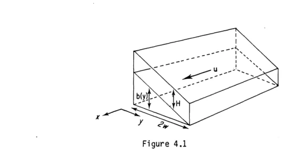
The flow will be confined to a channel aligned in the x-direction (see Figure 3.1). The channel bottom will vary in the x-direction on a
horizontal scale L. The width of the channel will have horizontal scale W while the depth and bottom elevation will have vertical scale D. Based
on these, we choose the horizontal velocity scales as U = (g'D)1/2 and V = UW/L. The former scaling implies that the advective terms in the x-momentum equation are important and is consistent with the observed
scales of many deep strait and sill flows (see Lousdale (1969), for example).
Dimensionless variables are now chosen as
x' = x/L, y' = y/W, t' =t(g'D)1/2/L,
u' = u/U = u/(gD)1/2, v' = v/V = vL/(g'D)1 / 2W$
h = h/D, b' = b/D.
substituting these into the shallow-water equations and dropping primes, we find the following dimensionless set of equations:
u t + uu x + vuy - Fv = -h X - b x (2.1.1a)
62(v + uv + vv y) + Fu = -hy - by (2.1.2a)
ht + (uh) + (vh)y = 0 (2.1.3a)
where
6 = W/L = (horizontal aspect ratio) and
F = Wf/(g'D)1/2 (width scale/Rossby radius of deformation) Solutions to (2.1.1a-2.1.3a) will be discussed according to the following program:
Chapter 1: 6 << 1, F << 1, =0 ay Chapter 2: 6 << 1, F = 0(1), b = 0 Chapter 3: 6 = 0(1), F = 0(1)
We start by considering the first parameter range, for which the flow is one dimensional and nonrotating (see Figure 2.1). The governing
, b (x) b. Figure 2.1 Definition sketch. 3.6 i 3. - 3.5 3.2 3.0 ~. B=3.0 2.8 - 2.7 2.6 26-B= 2.5 2.4
-2.2 -3
2.0 1.8 .7 1.6 1.4-1.2 1.0 .8 -6 -2 2.5 .4 .2 OBSTA 0 1 2 3 4 5X
6 7 8 9 10 Figure 2.2db
+ uu, + h = - b (2.1.1)
ht + (uh) = 0 . (2.1.2)
Equations (2.1.1) and (2.1.2) have been studied extensively in connection with open-channel hydraulics (Chow, 1959) and shallow-water waves (Stoker, 1957). Steady solutions can be found by direct integration with respect to x, resulting in
2
2 + h + b = B = (flow energy/unit mass) (2.1.3)
uh = Q = (flow rate) , (2.1.4)
and these can be combined into a single equation for the fluid depth: 2
+ h + b = B. (2.1.5)
2h
A family of interface elevation curves are drawn in Figure 2.2 for flow over an isolated obstacle. The flow rate Q is held constant while the Bernoulli constant B is allowed to vary. It can be seen that two distinct solutions exist for each large value of B and that each maintains the same depth on either side of the obstacle. As B is reduced, however, a critical value (B = 2.5) is reached at which the two curves coalesce over the sill of the obstacle. Here it is not obvious which branch is correct. After moving along the interface curve from
Q
to , for example, it is not clear whether one should proceed to G or G. Based on physical intuition we would likely choose0
since this branch resembles the commonly observed configuration of fluid flowing over a dam or weir.If B is further reduced the solutions no longer extend across the entire obstacle. The energy of the flow has been reduced to the point where the fluid is unable to surmount the sill. The solution for B = 2.5 contains the minimum energy necessary and is therefore 'controlled' in the sense that a small increase in the sill height would necessitate a time-dependent change in the upstream conditions for flow to continue. Such upstream influence would not be necessary for the other continuous solutions since they contain energy in excess of the required amount.
The steady solutions of Figure 2.2 also have distinguishing properties in terms of wave propagation. The only small-amplitude waves allowed by
(2.1.1) and (2.1.2) are long gravity waves with speeds
= u * (h)1/2 (2.1.6)
At the coalescence point (labeled 0 in Figure 2.2) the Bernoulli constant B has the minimum for all the profiles, T = 0. It follows from (2.1.3) and (2.1.4) that the flow there is critical (x_ = 0). Using uchc to denote the flow at the critical point, it also follows from (2.1.6) that
uc = hc1/2 , (2.1.7)
and from (2.1.4) that
Q = 3/2 , (2.1.8)
so that
X x=c h 3/2 -h 1/2 =b/ h1/ h12hc c 3/2 _ 1
- h h 3/2
It is further evident from the latter relation that the flow is subcritical (x < 0) for h > hc and supercritical (x > 0) for
h < h. Along interface 0 - 0, for example, the flow is subcritical
between and . The solutions which lie above interface
Q
--are completely subcritical, while those lying below - - are completely supercritical.
There exists a relation between the principle of upstream influence and the presence of a critical point and this will be explored in section 2.3.
2.2 Weak Solutions
We would like to know how the steady solutions of the last section undergo time-dependent adjustment to some sort of disturbance. The disturbance might take the form of a sudden change in the upstream conditions or change in the topography of the obstacle. Since the
hydrostatic assumption implicit in Equations (2.1.1) and (2.2.2) permits nonlinear steepening but not dispersion (Stoker, 1957), it is expected that this adjustment might result in wave breakage. We seek to describe the resulting discontinuities, or shocks, as 'weak' solutions in which the flow fields satisfy (2.1.1) an (2.1.2) at all but a finite number of points. At these points the height and velocity and their derivatives can be discontinuous, at least in the shrunken horizontal space of the shallow water approximation. In reality, the shocks occur over small but finite regions in which the shallow approximation breaks down. One example is the common hydraulic jump.
How does one connect the upstream and downstream states across a shock? Even in the presence of nonhydrostatic and viscous forces, the fluid
contains no internal sources of momentum or mass. We can therefore
integrate the continuity and momentum equations (in their conservation law form) across the shock. Upon doing so and shrinking the interval of integration to zero we find the Rankine-Hugoniot conditions (Stoker, 1957):
c[h] = [uh] (2.2.1)
A B A B
c[uh] = [u 2h + h 2/2] , (2.2.2)
A B A B
where [
]
denotes the jump from x = A to x = B and c is the A Bpropagation speed of the shock. The steps leading to (2.2.1) and (2.2.2) are worked out in Section 3.7 in connection with more general, two
dimensional shocks.
If c, uA, and hA are known then (2.2.1) and (2.2.2) provide two equations for uB and hB. These can be combined to form a cubic equation for hB containing at most two real roots -- one corresponding to a drop in depth, the other an increase in depth. It can further be shown that the rate of energy dissipation per unit mass of fluid crossing the jump from side 'A' to side 'B' is as given by (Rayleigh, 1914)
dE m (hA - hB)3 (
~d ~ hAhB ,(2.2.3) where m = hA(uA - c) = hB(uB - c).
t The conservation of mass within the shock is, of course, exact. The fluid may, however, gain momentum from viscous boundary layer or
topographic effects at a rate proportional to the distance over which the shock is smeared.
Since viscous effects act as energy sinks through the generation and dissipation of turbulence and small waves, we demand that a fluid parcel passing through the shock lose energy. Equation (2.2.3) then demands that the parcel's depth should increase upon passing the shock and this determines the appropriate root.
2.3 Adjustment of a Steady Flow to Small Disturbances
The remark has been made that hydraulically controlled flows are distinguished by the way they adjust to changes in obstacle height. We would now like to ask how this adjustment occurs and what the relevance
of the critical condition is.
We are therefore posed with an initial value problem in which one of the steady solutions to (2.1.1) and (2.1.2) is perturbed by a sudden change in topography. A convenient method of solving such a problem is
provided by characteristics and characteristic equations. Multiplying (2.1.2) by h-1/2 and adding the result to (2.1.1) gives
(aL + x a-)u + h-1/ 2 ( + )h = - d
at + a at + ax- h db
where x4 given by (2.1.6). Subtracting the product of h-1/2 and (2.1.2) from (2.1.1) leads to
(a ., a)u - h-1/2 (a + x )h = - db
5T _ axu - ha+x -dx .
These equations can be written in the more compact forms d+U -1/2 d+h -db + h =- (2.3.1) and du- h-1/2 d h (2.3.2)
a -
If'd
2..2where the operator
= + (u * h) /2a
(2.3.3)
t at a
denotes differentiation following a wave with speed dx,/dt = x= (u * hl2). The characteristic curves, x,(t), map out the paths of wavelets as they carry information along the channel.
Equations (2.3.1) and (2.3.2) determine the evolution of u and h along characteristic curves x,(t). A simpler form can be achieved if it is noted that h-1/2dh/dt = d(2hl/2)/dt in (2.3.1) and (2.3.2). This leads to evolution equations for the Reimann functions defined by
d+
1/2
d+R+
-db (u + 2h ) = =(2.3.4) and d- - 1/2 d R -db (u - 2h t -1/t dx~ (2.3.5)The Riemann functions, R., are therefore invariant along appropriate characteristics if the channel bottom is flat.
If R. are known then height and velocity fields can be determined from them through
1
u = 1 (R+ + R) (2.3.6)
h = 1- (R+ - R) 2 . (2.3.7)
Given initial data along some line OQ (Figure 2.3a) not a characteristic, we can integrate (2.3.4, 5) or (2.3.1, 2) along characteristics which
intersect OQ to find a solution in the region POQ. Furthermore, the information specified along OQ will continue to propagate away from POQ
(a)
(b)
- - SUBCRITICALSUPERCRITICAL
+ + I, i / I / + /I/ /O1
X 0
0 0 Figure 2.3Now consider the general pattern of characteristics for each of the four types of steady solution. These have been drawn in Figure 2.3. For subcritical flow the x characteristics tilt upstream and the
x. characteristics downstream, while for supercritical flow both sets of characteristics tilt downstream. In either case a small
disturbance generated over the sill will propagate away from the obstacle as two separate packets.
For transitional flow (Figures 2.4 c,b) the slope of the x
characteristics depends upon position relative to the obstacle. At the sill the flow is critical, so that the x characteristic is vertical there. In the
(
-G
case (Figure 2.3c) the neighboring xcharacteristics diverge as the sill acts as a source of characteristics for the far field. The x_ packet synthesized by raising the sill a small amount therefore spreads out, eventually covering the entire channel.
In the
Q
-0
solution, however, the characteristics converge over the obstacle and x_ waves tend to become focused about the sill. Apparently, this branch is unstable.We see that there is a fundamental difference between the way that transitional and nontransitional solutions adjust, and that this
difference is related to the existence of a critical point. We now
attempt to quantify this idea in terms of the upstream influence that the disturbance has. Consider the flow at a point P upstream of the
obstacle long after the disturbance has been generated and a new steady state established (see Figure 2.3a). Let the Riemann functions be
associated with the disturbance. The values of R, are determined by the initial (t = 0) data and r. are zero at t = 0. The upstream influence of the obstacle is then measured in terms of rp.: the changes in the Riemann invariants at the point P after a new steady state is reached. The new values of the Riemann invariants can be translated into new heights and velocities using (2.3.6) and (2.3.7).
The values of rp* can be obtained by replacing R+ by -R + r. in (2.3.4) and (2.3.5) and integrating along appropriate characteristics
Q'P and O'P (see Figure 2.4 a,b). Using the fact that r0'+ = rQI+ = 0, we obtain
r_ = (E,- -- J) dt' (2.3.8)
'db'
= (R=
M,
Rs)
-j
db- dt'
(2.3.9)
where d is the slope of the new topography. The integration paths should be distinguished from the characteristics PQ and PO that would be appropriate in the absence of a disturbance. Since the channel bottom is flat between 0' and P, 0 - and
fdt'
=0. Thus rp+ = 0 and the upstream influence is entirely due to rp_.Let us examine (2.3.8) first for the subcritical and supercritical cases (Figures 2.4 a,b). Since the initial flow is steady, the depth and velocity on either side of the obstacle is identical. Therefore -,=
RQ = R Q. and (2.3.8) reduces to
r - f db' d
in either case. If the flow is supercritical then the characteristic PQ' lies entirely over flat bottom and this integral vanishes. If the flow is subcritical, then (2.1.5) implies that the new steady solution that is established is a single-valued function of b' alone and
P db' P db' 0 db'
rp - J t'dX = -
f
Q dx/dt' 0 Thus, the upstream influence is zero in either case.The first transitional case (Figure 2.2c) is somewhat more subtle.
First consider (2.3.8) when no disturbance is present (i.e. b' = b, r, = 0,
Q=
Q, and Q lies close to the sill). Since rp_ = 0 we haveP -
Q
=Q dx
both sides being finite.
Now suppose that the flow is disturbed (Figure 2.4c). The x_
characteristic passing through P will still originate from near the sill; that is, Q > Q' as the point P is moved toward t = - while x is kept fixed, and R - RQ will remain unchanged. We can therefore rewrite
(2.3.8) as
r _ =
I_
Q
dt - Pdb dt' , (2.3.9a)d
Q
d
where dt is taken along the undisturbed characteristic between Q and P, and dt' is taken along the new characteristic (that also spans Q
and P). For b / b' the above expression will be nonzero in general and upstream influence will be present.
With slight modification, the above arguments can be made for P taken downstream of the obstacle. We therefore eschew the traditional term
Figure 2.4
Perturbed and unperturbed X characteristics.
(a)
SUCRITICAL
-\ \ \\QQ'
(b)
TRANSITIONAL
P
I \ + \-+, | I/00
Q=Q'
(b)
SUPERCRITICAL
Figure 2.5X_ characteristic curves for nearly critical flows.
P
II +j00,
t0
(a)
SURCRITICAL
'upstream influence' in favor of the term 'far-field' influence so that the upstream and downstream fields are both considered. Thus far, the 'far field' includes any point away from the obstacle. That is, the response as t > c at a point near the obstacle is identical to the response far from the obstacle. It remains to be seen whether further complications will cause responses which vary with the distance from the obstacle.
The above analysis assumes that the general pattern of characteristics remains unaltered by the change in topography. This does not apply to the second transitional flow (Figure 2.3d) which has been postulated to be unstable. A small change in the sill height here might lead to large distortions in the field of characteristics. Upon closer inspection of Figures 2.3a and 2.3b, we see that circumstances may arise which render subcritical and supercritical flows unstable as well. Suppose that the flow is initially supercritical or subcritical but that conditions over the sill are nearly critical. The corresponding characteristics are
sketched in figure 2.5. In the subcritical case the x_ modes synthesized downstream of the sill will tend to become focused about the sill. The
same happens in the supercritical case to x modes generated upstream. Both of these flows appear to become less stable as conditions near the sill approach criticality.
It should also be noted that no such behavior is possible for the first transitional flow (Figure 2.3c). This configuration appears to be the most stable of the four.
2.4 'Far-Field Influence' in Quasi-linear Hyperbolic Systems.
In the previous section we drew a connection between criticality and the idea of far-field influence. This was made possible by the
characteristic formulation in which solutions to initial-value problems are obtained through integration along wave paths. A generalization should then be possible for two-dimensional hyperbolic systems since, by definition, initial value problems are solved in the same way.
Consider the quasi-linear system of equations au.
au (x,t) + a .(u.,x,t) (x,t) = b (uilx,t) i = 1,n (2.4.1)
j
= 1,nwhere a.. and bi are single valued and continuous. Following Whitham (1974), Chapter 5, we wish to investigate the conditions under which
(2.4.1) can be expressed in the same form as (2.3.1) or (2.3.2); that is, the form
.d (n)ui
i dt - lb . (2.4.2)
where
d(n
_
+n
Ci.xt)
)
is a derivative along some curve-Ut- = at + (n) (i '~t ax
with real slope x=
It is clear that such a form exists if a vector 1 can be found such that
1 a = (n)1
for (2.4.1) can then be multiplied by 1 to yield (2.4.2):
a au. au.
1 ia i(x,t) iijiax + 1 a J = 1 I tii(n) u (x,t) + 1 X
ax
(2.4.3)
d u.
= 1 t(n) = l.b.
If 1 is a function of ui alone, a Riemann function R which satisifes
=R 1(2.4.4)
may be found. In this case (2.4.2) can be written in the simplified form d (n) R
dt 1 1ib.
The Riemann function is invariant along characteristics if the 'forcing' 1. bi is zero.
In order for (2.4.3) to be satisfied the eigenvalue, X(n), must satisfy
a - (n) 6ij = 0 . (2.4.5)
We note that if a.. is constant and bi = 0 then solutions to (2.4.1) of the form
u = A ieik(x - X(n)t)
exist, provided that (2.4.5) is satisfied. The X(n) are therefore called characteristic speeds.
If n real values of x can be found to satisfy (2.4.5) then n linearly independent equations of the form (2.4.2) can be written and the
initial-value problem solved in the way suggested above. Under these conditions, the system (2.4.1) is hyperbolic and steady solutions
containing critical points (xn = 0) may display far field influence. This will occur if the characteristics diverge from the critical point, thereby connecting the far field to a single point.
In the steady solutions of Figure 2.2c the flow at the bifurcation is critical. Is this a general property of bifurcations of steady flows Using (2.4.1) the derivatives of the dependent flow variables can be expressed using Krammer's Rule in terms of ui and x as
au= a . ,i
(2.4.6) where aij is the determinant obtained from a by replacing the
ith column with bg . If the solution bifurcates at some point xc' either aui/ax or one of its higher derivatives becomes multivalued.
Suppose first that aui/ax becomes multivalued, so that the right side of (2.4.6) must be also. Yet each element of a.. and bi, and therefore each determinant, is single valued. The only possibility for multivaluedness is for
|ajk| = 0 (2.4.7)
and
Iajk i = 0 . (2.4.8)
The first result together with (2.4.5) implies that one characteristic speed must be zero. The second gives a connection between the bifurcation point and the inhomogeneous term b .
It is also possible that a higher derivative of ui, and not au1/ax, is multivalued. In this case differentiation of (2.4.6) yields the
condition that anu./axn is multivalued if and only if an-iu./axn-1 is. Thus (2.2.1) and (2.2.2) are applicable in all cases.
As an example, let us apply the general theory to the shallow flow under consideration. Here,
ui = (u h) a = (h ) b = ( d 0)
The characteristic speeds are obtained through the use of (2.4.5): = u + h1/2
and
x = u - h
Equation (2.4.3) then gives the eigenvectors 1+ and 1_ within a multiplicative constant. One choice is
1+ =(1,h-1/2 )
1 = (1,-h-1/2)
Multiplying equations (2.1.1) and (2.1.2) by these gives the characteristic equations:
d+U + h-1/ 2 d+h -db
- h- 1/2 dh -db
dt dt dx
Finally, (2.4.7) requires that bifurcations of steady solutions must occur when c_ = 0, while (2.4.8) further demands that any such point must occur where
b' -1 u b'
0 u ~ h 0 =0,
that is, when b' = 0.
The steady solutions of this example are subject to far field
influence only if a critical condition exists. We should hasten to add that this is not a general property of hyperbolic systems. For example,
in a channel flow with quadratic bottom friction (i.e., bi = [-db/dx
-(cf u2/h 0]),t the Riemann functions are nowhere conserved. The
arguments of the previous section indicate that far field influence will be present for any steady configuration. Physically speaking, any change in an obstacle's height causes a change in the net frictional force exerted by the obstacle against the upstream flow.
2.5 Establishment of Steady Solutions
The adjustment of a stable steady flow to a small change in topography is convenient to analyze because the basic pattern of characteristics remains fixed. What adjustment occurs when the initial flow is unstable, or when the change in topography is large?
To answer this we consider an initial value problem which is similar in concept to the laboratory experiments of Long (19 54).tt The initial state, shown in Figure 2.6a, consists of a uniform flow with depth h
0 and velocity u0. At t = 0, -an obstacle of height b0 is quickly grown in the channel and the fluid is forced to adjust. The subsequent motion has been computed numerically using a Lax-Wendroff (1960) scheme which allows shocks to form and be maintained, insuring that mass and momentum
flux are conserved across discontinuities. The numerical method is described in Appendix A.
We wish to make comparisons between the numerical solutions and the steady solutions of Figure 2.2. In the steady solutions, flow over the
t Chow (1959).
(a)
INITIAL STATEbo
=0
bo
<bc
(b) NO BLOCKAGE
bb 2
bo
2
b
JUMP
(C) PARTIAL BLOCKAGE (INITIALLY SUBCRITICAL)
bbabobc
(d) PARTIAL BLOCKAGE (INITIALLY SUPERCRITICAL)
(e) TOTAL BLOCKAGE
Figure 2.6
obstacle is possible only for B > 2.5. More generally, a steady solution is possible only if the flow energy is greater than some minimum value determined by the critical condition. When the flow is critical, then
(2.1.5) and (2.1.8) give
B bc+2 +h b+3 Q 2/3
B c +.7 - +h=bc +T
2h
where bc is the sill height. Alternatively, given Q and B we can say that steady solutions are possible for obstacles having less than the critical height given by
3 2/3
bc =B -
Q
2.
The adjustment depends crucially upon how high the obstacle is grown in relation to bc. In particular, if b0 < bc the obstacle growth
results in two long gravity wave packets which move away from the obstacle, one propagating upstream and the other downstream relative to the flow (Figure 2.6b). These gravity waves leave the steady state unchanged except for a deformation in the interface over the topography. Thus, the upstream flow 'feels' the obstacle only temporarily and the asymptotic state resembles one of the supercritical or subcritical curves of Figure 2.2.
If b0 > bc the adjustment is quite different. After the obstacle appears, a front is formed which moves upstream and begins to steepen (Figure 2.6c). The front eventually breaks and forms a bore which leaves behind a new steady state resembling branch 0 - Q of Figure 2.2. This branch is realized regardless of whether the initial flow is subcritical or supercritical; in no case is branch - realized. The downstream state depends upon whether the initial flow is subcritical or supercritical.
In the latter case a bore and rarefaction wave form which move downstream leaving behind another supercritical state. If the flow is initially
subcritical, the bore and rarefaction wave leave behind a subcritical flow with a hydraulic jump on the lee side of the obstacle (Figure 2.6c). A
computer drawing showing the evolution of the bores and hydraulic jump appears in Figure 2.7.
Once the controlled configuration is realized a further increase in b0 will cause a new bore to be generated which moves upstream and leaves behind a new controlled state. Eventually a height, bbs will be reached at which the upstream flow is completely blockedt (Figure 2.6e). In this case, the Rankine-Hugoniot conditions (Equations 2.2.1 and 2.2.2), when applied to the bore, give
c(bb - h
0) = 0h0
and
-b 2 h 0
c(u0h0) ~-2-- u0 h0 +
These can be combined into an equation for the blocking height in terms of the initial conditions alone:
b b3 b b2 2 1 bb
(,F-) -( ) - 2(F02 + ) + 1 = 0 ,
0 0 0
where F0 = U0/h1
Once the controlled state is established (i.e., bb > b0 > bc) it is interesting to observe the effect of lowering the obstacle to a new
t It is not possible to model complete blockage numerically as the numerical scheme will not handle zero depth.
t =200 (time steps) b re * bore '7 bore. rarefaction wave U -obstacle 0 20 40 60 80 100 120 140 160 180 200 t =800 80 100 120 140 160 Figure 2.7
Nonrotating adjustment for bc < b0 < bb showing development of bores and hydraulic
jump.
Q
0 = .7, BO = 1.25..2
.2I
height, b0 0. If the initial state was subcritical, so that a jump forms in the lee of the sill after control is established, then the flow returns to a subcritical state if b00 < bc. In this case the jump moves upstream
over the sill and 'washes' out the critical flow. However, if the initial flow was supercritical (no downstream jump exists), then the obstacle must be lowered to a new height, bcc < bc, for the supercritical flow to
become re-established. In this case, a hysteresis occurs which tends to keep the fluid in its controlled state. The supercritical flow is
re-established when the upstream propagating bore reverses its direction and moves back downstream over the obstacle. A computer drawing of these events is shown in Figure 2.8.
The height bcc is the value necessary to maintain a stationary bore upstream of the obstacle and is calculated from equations (2.2.1), (2.2.2) and (2.5.1) with c = 0. In particular (2.5.1) gives
b =B 3 2/3 cc 1 2 0
where B1 = -1-- + h1 is computed from
u0h0 = u 1h, and 2 2 2 u02 h0 + ho2 U 2 h + . 0 0 -u 1 h1 2
These can again be combined into an expression for bcc invol ving only the initial conditions:
cc 0 2 3 2/3 3 21/2
F7= 1/2 ~ 7F0 , [(1 + 8FO [(1 + 8F0 2) _ 1
1.4
t= 400
(a)(time steps)
Initialbore
1.2
rborerefoCt i adjustment wave bore for b0
.8 b c .- bore U (b)
l2
-b
b
0> b:
Z
bo
e ., . I ') 1. Bore moves 0 20 40 60 80 100 120 140 160 180 20 LQ 2.2 , , , , , , , , , , , , , upstream,t=
3200
establishing 1 .8 controlled 1.6 -flow. 1.2 -1.0 .8 --.6 U 0 20 40 60 80 100 120 140 150 180 200 Figure 2.8Hysteresis of surface for initially supercritical flow c= .160, bcc = .112.
2.0 -(c) -. -At t = 2200
t= 22OO0
1.5- time steps, 1.4 b is 1.2- suddenly 1.0 decreased to .8 .135 (i.e., .6 U b > b > G .4c 0 b> S .2cc 0 20 40 60 80 100 120 140 8O0 ISO (d S(d) Despite the-
t= 42OO
lowering of 1 the obstacle 1.2--in part (c), 1.0 the bore .8 -continues to .6 U move upstream, .2 -establishing 0 20 40 50 80 100 120 140 160 180 20W 2 2a controlled flow.1. 3000 (e) 1.4 The obstacle 1.2 -is launched 1.0 so that b > .8 -- c .6 bcc > b0 = U causing the 4 -~ bore to S .2-reverse. 0L] 0 20 40 60 80 100 120 140 160 180 200 -- j x 1.6 . . . , . , .(f )
t.-
=
2The
bore . -moves ~1.2 backward 1.0 over the .8 -obstacle, re-.6-establishing
.4- the initial .2 - supercr i ti cal o , , I - -1 1 ' 1 flow. 0 20 40 60 80 100 120 140 160 1f 2 flw xThe hysteresis effect has been predicted by Baines and Davies (1980) but has not, until this point, been verified numerically or
experimentally.
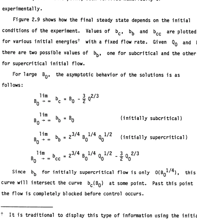
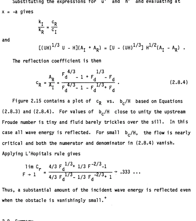
Figure 2.9 shows how the final steady state depends on the initial conditions of the experiment. Values of bc, bb and bcc are plotted
for various initial energiest with a fixed flow rate. Given
Q
0 and I there are two possible values of bb, one for subcritical and the other for supercritical initial flow.For large Bo, the asymptotic behavior of the solutions is as
follows: B 3 Q2/3 = B0 - 2 = B 0 bb=23/4 B01/4
Q01/2
b = 23/4 B 0 4 Q 1/2 cc 0 0 (initially subcritical) (initially supercritical) 3_ 2/3 2 0 Since curve will the flow ibb for initially supercritical flow is only 0(B0 1 4), this intersect the curve bc(BO) at some point. Past this point
s completely blocked before control occurs.
t It is traditional Froude number, F0, later in experiments
parameters B0 and
to display this type of information using the initial rather than B0. However this will prove difficult with rotating flows. We therefore use the initial
Qo which prove to be convenient in later results. lim B0 -* 00 lim B0 -* lim B0 , 00 lim B0 + 00
7.0:
6.0
5.0
4.0
3.0
2.0
1.00
1.52.5
3.5
4.5
25.5
/N/TAL
ENERGY
B
=hO
6
802
06.5
Figure 2.9
Asymptotic states for various initial energies with QO = 1-Key
A - all flows blocked
B - initially supercritical flow is blocked C - all flows controlled
P - initially supercritical flow
is blocked, initially
subcritical remains subcritical
E - initially supercritical flow is subject to hysteresis, initially subcritical remains subcritical
2.6 Unsteady Flow
The discussion of steady flow has centered around the role of the obstacle height in the establishment of upstream influence. Now consider an unsteady stream which passes over an obstacle and oscillates with time but does not reverse the flow (i.e. u is always > 0). This is
typically the case in many deep oceanic straits (see Figure 1.2, for example). How important is the height of the obstacle in determining the far field flow? Since analytic solutions for nonlinear unsteady flow over topography are generally unavailable it becomes difficult to make interpretations using bifurcations and branches. The characteristic formulation used earlier, however, still provides an intuitive tool in evaluating the role of the obstacle height.
Consider the wave-like flow shown in Figure 2.11. The flow is set up (numerically) by oscillating the depth of an initially steady, controlled flow periodically at a point upstream of the obstacle. The oscillatory forcing results in a train of waves which propagate downstream and are partially transmitted across the obstacle. The waves can be considered
'large' in the sense that their amplitude and length are of the same scale as the obstacle. After the passage of several waves the flow field over
the obstacle became nearly periodic and the characteristics (Figure 2.10) take on a wavey appearance while retaining the same general geometry as
the ones in Figure 2.3a. Conditions at the sill alternate from a subcritical (x < 0) to supercritical (x+ < 0) in a periodic fashion. Upstream of the obstacle the unsteady flow is subcritical at all times, while a region in which the flow is always supercritical exists between
SILL 100 I 1 I x- x- x- x-CRITICAL 90 CURVE 80 70 -60 b 30 F 20
L
10 0 5 10 15 20 2 30 3.5 40 45 50 SILL Figure 2.10X characteristic curves for unsteady flow over an obstacle. The dotted line traces the path of critical flow. The sill lies at x = 25.5.
1.2 1.1 1.0 .9 .7 .5 .4 .9 1.1 1.0 .2 1.0 .7 .9 .5 1.1 1.0O .7 .8 .5 1. 1 1.0 ., .8 .,7 .3 .29 incident wave of elevation u 180 200 220 240 260
Establishment of oscillatory flow by periodic upstream forcing. \jump 20 40 80 s0 100 120 140 180 Figure 2.11 bstacle r o
(a)
t = 0
(b)
t =250
(timesteps)
(C)
t
=350
t=700
(e)
t =
1400
-~1. K '1J-j K 1.2 1.1 1.0 .8 .7 .2 .S .4 .3 .2 0 1.1 -1.0 .9.6 .7 .5 .-.0 .9
(a)
t= 150
(b)
In the steady, controlled flow of Figure 2.3c, far field conditions can be traced back to the sill through integration of (2.3.5) along x_
characteristics. In Figure 2.10 the x characteristics diverge from a dividing characteristic (marked x0) rather than from the sill. Such a characteristic must exist by virtue of the fact that the sill is bordered
upstream by a region of subcritical flow and downstream by a region of supercritical flow.
Suppose that the obstacle height is suddenly increased by a small amount. What is the far field effect? We first note that if R, are taken to represent the unperturbed unsteady fields and R* + r, the
perturbed unsteady fields, then rp, measures the response at point P to the change in height, as in Section 2.3. In particular, if P lies away from the obstacle then the arguments leading to (2.3.9a) continue to hold and
r = 1P dt - dt' . (2.6.1)
The integration path is now a characteristic which extends from P to a point Q lying on x0
at the initial instant. The value of rp
depends in a complicated way on the new topography, b'(x), as well as the integration paths.
Equation (2.6.1) links the far field to the dividing characteristic. How is the dividing characteristic related to the geometry of the obstacle? Suppose that the flow is periodic with longest period T, so that
R+(x,t) = R+(x,t + T). Integration of (2.3.5) along the dividing characteristic over one period then yields
R_(x,t + T ) - R (x,t) = - db dt = 0
t
dx
Thus, the dividing characteristic must spend an equal time on either side of the sill as weighed by the bottom slope; if the slope is steeper on one side the curve must hug the sill more closely on that side or spend less time there.
How far from the sill can the dividing characteristic stray? In Figure 2.10 the downstream and upstream extremities of the dividing characteristic are labeled a and b respectively. Since the flow is critical at a and b (x0 is vertical there) the dividing
characteristic must occur within the envelope of the curve along which the flow is critical (shown as a dotted line in Figure 2.10). Although the critical curve is of less dynamical significance in the unsteady case, its geometry gives information concerning the confines of the dividing curve. At a', where the upstream excursion of the critical curve is maximum,
c~ = ac~/at = 0 so that
-dR_ -aR- ah1/2 ac- ah1/2 db
dt ~ at at at ~ at -fx > 0 (2.6.2)
Thus the depth increases with time at a' (and decreases at b').
Equation (2.6.2) also indicates that obstacles with sharp crests will tend to confine the critical point more so than obstacles with rounded crests. Furthermore, as the height of the forced wave grows larger the excursion of the critical point only increases as the square root of this height, assuming that changes in the shape of the wave can be neglected.
If the flow is initially subcritical, the periodic state set up has wavy characteristics which are similar in appearance to those of
Figure 2.3a. Despite this, upstream influence can be exerted by the topography, as a reexamination of Equation (2.3.8) will show. Again we consider the influence r'_ at a point P upstream of the obstacle long after the adjustment has occurred and a new unsteady state established. The response depends on the initial conditions as well as an integration along an x characteristic from P to a point Q' downstream of the obstacle. Unlike the steady case, however, it is no longer true that
RQ = RQ,. Nor is x_ a function of db/dx alone, and the symmetry property that caused the steady integral to vanish no longer holds. Therefore, upstream influence may be present in the unsteady subcritical case for obstacles of any height because of the wave response to
topography.
At this point the meaning of the term 'hydraulic control', as applied to unsteady flows, should be clarified. Traditionally a flow is said to be controlled if far field influence is exercised by some discrete
topographic point. This is a meaningful concept when applied in steady situations but becomes vague in the unsteady case due to the fact that influence is exerted by a continuous distribution of points. We therefore reserve the use of the term 'control' for steady situations.
This is not to say that upstream conditions in the flow of Figure 2.7 are equally sensitive to changes in the sill elevation as to elevation changes elsewhere. We have seen that all x_ characteristics originate from a dividing characteristic that is tied to the sill through Equation
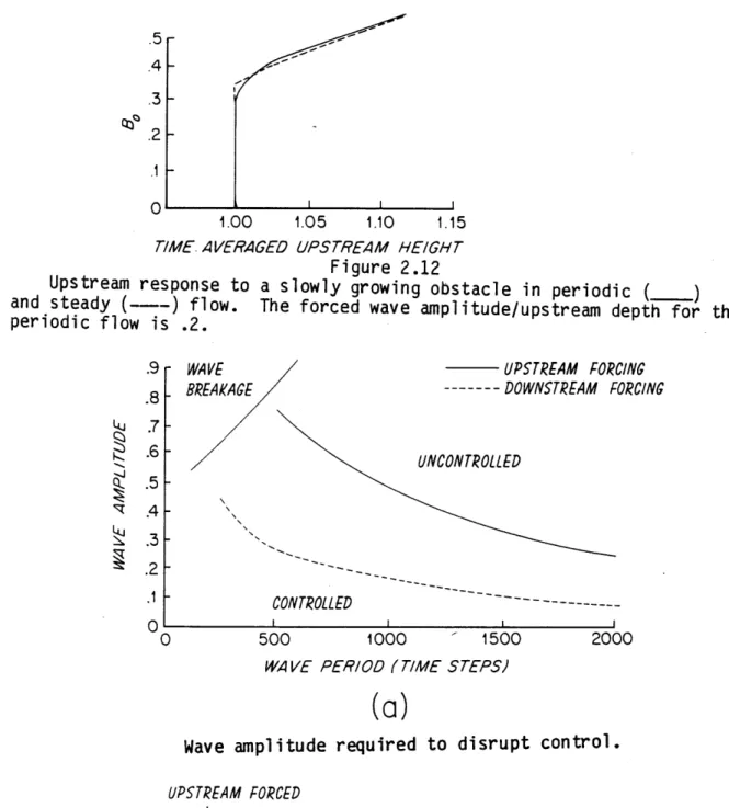
(2.6.2). Figure 2.12 shows the result of a numerical experiment in which an obstacle is grown in a periodic flow over an initially flat bottom.
The time-average upstream height (measured after the adjustment occurs) is plotted for various obstacle heights. The result is compared to the result of doing the same experiment using an initially steady flow whose velocity and depth equal that of the time-average initial periodic flow. In both cases there is little or no upstream influence until the critical obstacle height for the steady flow, bc, is reached. However, when
b0 > b c a dividing characteristic appears in the forced flow and this is
followed by a change in the mean upstream height.
2.7 Disruption of Control
The characteristics of Figure 3.10, although wavelike, are similar to those of a steady controlled flow, with a dividing characteristic playing the same role that the critical characteristic does in Figure 2.3c.
Suppose now that the oscillations become larger in relation to the mean fields. Will the dividing characteristic remain, or will some new characteristic regime be established? As long as subcritical flow is
maintained upstream and supercritical flow downstream of the sill, a dividing characteristic will continue to exist. Therefore some change in
these conditions is necessary in order that the dividing characteristic be swept away.
The dividing characteristic might be swept away if the incident waves contained regions of supercritical flow. However, such waves would
rapidly break and the situation would probably not be typical of deep strait and sill dynamics. However, if a hydraulic jump exists in the lee of the obstacle, then the incident wave may be able to cause the jump to
32
move upstream across the sill and establish subcritical flow everywhere. In this case the dividing characteristic would be swept away.
Consider the flow shown in Figure 2.13b. Over the obstacle the fields are steady and controlled and a hydraulic jump exists in the lee of the sill. Upstream, an isolated wave approaches. This wave collides with the obstacle and displaces the hydraulic jump. If the jump is displaced
upstream past the sill, creating a flow that is everywhere subcritical, then we say that control has been disrupted. Numerical results which show the amplitude of the incident waves required to disrupt control will be discussed presently, but we first try to develop some intuition into the effects of waves on jumps.
Consider a jump which lies at position q(t) in a flow over a flat bottom. The position is determined by the Rankine-Hugoniot conditions
(2.2.1) and (2.2.2) with c = dn
dt (h - = h- h (2.7.1)
and
dh2 h 2 h 0
T (uh - u0h0) = hi + - u0 2h0 ~ ~2- (2.7.2) where h0 and h, are the depths immediately upstream and downstream.
If the jump is stationary then
u1hi = u0h0 (2.7.3)
and
22
2 h1 2 h0
u 1 h +- = u0 h0 + . (2.7.4)
It can be shown from these that
hl/h0 [(1 + 8F12 1/ 1] = (F12 + 1)/(F2 + ).1