A Doubly-Fed Permanent Magnet Generator for
Wind Turbines
by
Andrew Joseph Thomas
Submitted to the Department of Electrical Engineering and Computer Science in partial fulfillment of the requirements for the degree of
Master of Engineering in Electrical Engineering and Computer Science
at the
MASSACHUSETTS INSTITUTE OF TECHNOLOGY
June 2004
@
2004 Andrew Joseph Thomas. All rights reserved.The author hereby grants to MIT permission to reproduce and distribute publicly paper and electronic copies of this thesis document in whole or in part.
Author ...
Departmen of Electrical Engineering and Computer Science
May 25, 2004 Certified by... Professor of James L. Kirtley, Jr. Electrical Engineering Thesis Supervisor Accepted by ... Arthur C. Smith Chairman, Department Committee on Graduate Students
MASSACHUSETTS INSTI ITE
OF TECHNOLOGY
A Doubly-Fed Permanent Magnet Generator for Wind Turbines by
Andrew Joseph Thomas
Submitted to the Department of Electrical Engineering and Computer Science on May 25, 2004, in partial fulfillment of the
requirements for the degree of
Master of Engineering in Electrical Engineering and Computer Science
Abstract
Optimum extraction of energy from a wind turbine requires that turbine speed vary with wind speed. Existing solutions to produce constant-frequency electrical output under wind-speed variations are undesirable due to complexity, cost, inefficiency or reliability issues. We propose a novel variation of a doubly-fed induction generator which aims to improve power density and simplify construction. Our design is a doubly-fed, dual-rotor, axial-flux, permanent-magnet machine. Progress in the construction of a prototype is described. Analysis of the steady state and dynamic behavior of the machine is detailed, and a control algorithm developed therefrom.
Thesis Supervisor: James L. Kirtley, Jr. Title: Professor of Electrical Engineering
Acknowledgements
I would like to thank Professor Kirtley for his assistance, advice, and supervision over the course of the project. Funding for the project was generously provided by a grant from the National Renewable Energy Laboratory. I would also like to thank fellow graduate student Shiv Reddy for help with the design and construction of the prototype. The assistance of Colin Wu and Saagar Gupta in various construction operations has been critical to the progress of the project. Steve Englebretson, Jack Holloway, Riad Wahby, Mariano Alvira, Rob Cox, and Tim Abbott provided extra sets of hands when occasionally required for construction. Finally, I would like to thank Kate Baker, Cat Miller, and Reid Barton for their patience while editing this document.
Contents
1 Introduction 11 1.1 Prior Work ... ... 11 1.1.1 Induction Generators. . . . . 12 1.1.2 Synchronous Generators . . . . 12 1.1.3 Doubly-fed Generators. . . . . 13 1.2 Our Solution . . . . 14 1.3 Overview . . . . 16 2 Construction 17 2.1 Structural Elements . . . .. . . . . 172.1.1 Power Rotor Plates. . . .. . . . . 18
2.1.2 M agnet Rotors . . . . 19 2.1.3 End Plates . . . .. . . . . 20 2.1.4 Housing . . . . 20 2.2 M agnetic Cores . . . .. . . . . 21 2.3 W indings . . . . 23 2.3.1 Stator . . . .. . . . . 24 2.3.2 Rotor . . . . 25 2.4 Other Parts . . . .. . . . . 28 2.4.1 Shafts . . . . 29 2.4.2 Slip-Rings . . . . 31 2.4.3 Ventilation . . . . 32
2.4.4 Mounting and Testbed . . . . 33
2.5.1 Power Rotors . . . . 34
2.5.2 Stator M ounting . . . . 35
2.5.3 Final Assembly . . . . 36
3 Analysis and Modeling 39 3.1 Steady-State Behavior . . . . 39 3.2 Dynamics . . . . 41 3.2.1 Power Rotor . . . . 42 3.2.2 Stator . . . . 45 3.2.3 Overall Behavior . . . . 46 3.2.4 M odel Simplification . . . . 47 4 Control 49 4.1 Algorithm . . . .. . . . . 49 4.2 Electronics . . . .. . . . . 50 4.2.1 Sensors . . . . 52 4.2.2 Controller . . . .. . . . . 53 4.2.3 Power Converter . . .. . . . . 54 5 Conclusion 59 5.1 Completed Tasks . . . . 59 5.2 Further W ork . . . . 60 5.3 Summary . . . . 61
A Structural Part Drawings 63
List of Figures
1-1 Machine Cutaway View . . . . 15
2-1 Shape of Permanent Magnets . . . . 19
2-2 Assembled "Skeletal" Housing . . . . 22
2-3 Stator B-H Characteristics for 100 Vrms 60 Hz Sinusoidal Drive . . . . 25
2-4 Schematic Representation of Rotor End-Turn Configuration . . . . 27
2-5 Histogram of Rotor Winding Inductances, First Pass . . . . 28
2-6 Histogram of Rotor Winding inductances, Second Pass . . . . 29
2-7 Driveshaft Plan View . . . . 30
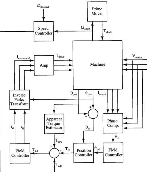
2-8 Form of Stator Support Blocks . . . . 36 4-1 4-2 4-3 4-4 A-1 A-2 A-3 A-4 A-5 A-6 A-7 51 55 55 56 Machine Controller Block Diagram . . . .
Bi-directional 3-phase AC/DC/AC converter Sub-synchronous Rotor Drive Cricuit . . . . . Hysteresis Phase-Current Control Circuit . .
Power Rotor Plate Drawing . . . . Magnet Rotor Plate Drawing . . . . Endplate Drawing . . . . Original Housing Drawing, Page 1 . . . . Original Housing Drawing, Page 2 . . . .
New Housing Mounting Ring Drawing . . . .
New Housing Stringer Drawing . . . .
64 65 66 67 68 69 70 71 72 B-1 Completed Stator Core . . . .
B-3 Wound and Partially Fiberglassed Stator . . . . 73 B-4 Assembled Power Rotor, without Windings . . . . 74 B-5 Power Rotor with Windings . . . . 75
Chapter 1
Introduction
The world increasingly relies on electrical power to function, in areas ranging from trans-portation to home comfort. Most of the electricity in the world, and in the United States in particular, is generated from ever-dwindling reserves of petroleum. This presents a large problem both in the increasing scarcity of fuel and in the environmental effects of its use. Hence, investigation into renewable energy sources seems prudent in both financial and environmental terms.
Wind power is one such renewable source which shows fair promise of becoming eco-nomically viable in the near future. This will be particularly true if it can be made to more efficiently capture energy, thereby reducing cost for a given capacity. The intention of this thesis work, and the project of which it is a part, is to develop a novel generator design to that end. We also aim to produce and test a prototype to validate our analysis. The generator is to be a doubly-fed permanent magnet machine, constructed based on the design work in [1].
1.1
Prior Work
Extraction of the maximum energy attainable from the wind for a given turbine requires a turbine speed which is proportional to the speed of the wind. Thus, if one is to extract energy with maximum efficiency, one must allow the turbine to change speeds as the wind
1.1.1 Induction Generators
Many installed generators ignore the problem completely, running an induction generator at essentially constant speed. Although in principle an induction generator could operate over a large range of speeds (all super-synchronous) by allowing large slip, this would require that the rotor resistance be large. However, large rotor resistance translates to much dissipation in the rotor, and consequent inefficiency.
1.1.2 Synchronous Generators
Synchronous generators do not have the rotor resistance problem that induction machines do. They also allow more control of the reactive power generation. However, synchronous generators have an output electrical frequency proportional to the shaft speed, so some additional consideration is needed before interfacing the generator to a power grid.
To some extent, the problem that a given turbine has an optimal speed which changes with wind speed can be solved by varying the turbine geometry with wind speed. Ideally, doing so allows the optimal speed for the turbine to remain always at the synchronous speed of the generator even as the wind speed varies. Although work is progressing in this area, variable-geometry turbines are largely restricted to low-power applications, due to the immense stresses to which such a mechanism would be subjected in a large turbine (50 m in diameter, perhaps). Better results can still be obtained if the turbine speed is allowed to vary with wind speed.
One possible solution is to use a continuously variable transmission (CVT) between the turbine shaft and the generator shaft, and to use a synchronous generator. A CVT, appropriately controlled, allows the ratio of the two shaft speeds to be varied continuously over some range. Unfortunately, CVTs are mechanically complex and, in this application, are subject to substantial wear. Consequently, the devices are prone to mechanical failure and potentially have problems with low control-loop bandwidth.
The other obvious solution is to use a synchronous generator, but allow the shaft speed of the generator to vary with wind speed, as described in [2]. Obviously, the output electrical frequency then varies with the wind speed, and a power electronics package (generally a back-to-back PWM converter for low power installations, or a cycloconverter for high power) converts the frequency to match the constant line frequency. Such a scheme also
offers complete control of real and reactive power components. The main drawback to such an indirect grid connection is the high cost of power electronics, which for large installations may have to handle 1 MVA or more. Furthermore, the power converter must be carefully designed to be highly efficient, or the advantage of increased extraction efficiency will be offset by losses in the converter. Naturally, more efficient converters are yet more expensive. Finally, the power quality of the output needs to be considered. Requiring that the converter also be low-distortion adds further to the cost.
1.1.3 Doubly-fed Generators
The doubly-fed induction generator (DFIG) offers a convenient electromechanical solution, which should be reasonably cheap and not prone to wear problems. The operation of a simple DFIG is analyzed in [3]. The essential principle of operation is as follows: by injecting an AC current into the field windings of the rotor, the flux wave in the machine can be made to move with respect to the rotor. Seen another way, in the reference frame of the rotor, the flux wave will then rotate with a speed proportional to the electrical frequency of the AC current injected. From the reference frame of the stator, the apparent motion of the flux wave is then due to the frequency of the AC rotor current added to the mechanical motion of the rotor. Thus, the stator electrical frequency can be controlled independently of shaft speed by varying the frequency of the AC current. Specifically, then, with an appropriate control loop, the stator electrical frequency can be kept constant over variations in shaft speed. The power level of the rotor excitation will typically be an order of magnitude less than the rating of the machine, so the cost of the necessary electronics is similarly reduced over that required by an indirect grid connection scheme.
The DFIG has a number of other useful properties which also recommend it as a solution. Firstly, if the power electronics used to drive the rotor of the machine are designed correctly, perhaps using a back-to-back PWM inverter scheme as in [4], the system has complete control over output power (both real and reactive), and may operate in both sub- and super-synchronous regimes. Super-synchronous operation is particularly attractive, as it allows power to be extracted from the rotor as well, effectively increasing the capacity of the machine in as much as capacity is limited by armature heating. Secondly, it has been shown (e.g. in [5]) that DFIG wind turbines are more stable under grid fluctuations than standard induction generators. As wind power takes a larger share of the generation
load, stability will become a bigger issue, because local instabilities can potentially disable distribution on a very large scale.
1.2
Our Solution
Our proposed solution builds upon the apparent advantages of the DFIG by adding perma-nent magnets to the design. Modern permaperma-nent magnet materials offer savings in efficiency and space when used appropriately in electric machines [6]. Additionally, the use of perma-nent magnets simplifies construction, as they allow for much larger air gaps, which loosens the manufacturing tolerance. Furthermore, the magnetic cores in the machine can be sim-plified by eliminating the winding slots. Both of these considerations also greatly simplify the cooling of the windings in the machine.
Adding permanent magnets to a DFIG presents engineering challenges. The first is the question of how the permanent magnets, which inherently provide DC excitation, can be used in a generator in which the excitation needs to be AC. This is solved by placing the magnets in a separate, freely spinning rotor between the wound rotor and the stator. Essentially, the magnet rotor is dragged along at the stator electrical frequency and serves to drive flux across the air gap of the machine.
Having decided upon such a dual-rotor approach, manufacturability becomes a major concern. A standard radial-flux design would require the installation of the magnets in a free-spinning cylindrical shell between the rotor and stator. Such a shell would be difficult to design to be sufficiently structural to support the required loading, and even more difficult to manufacture and assemble. Our solution thus uses axial flux.
The specific geometry we have chosen is derived from the TORUS geometry introduced in [7]. The TORUS design consists of a toroidal stator with a Gramme-Ring winding, interacting axially with a pair of rotors (one on each side), each of which consist of an annulus of magnets, arranged in alternating polarity. Our modification is to allow the magnet rotors to spin independently of the shaft and to add two additional rotors outside of the magnet rotors. These rotors are also toroidal in form, but are face-wound because they have only one active surface, and the conventional end-turns are shorter. A cut-away view of our machine prototype, with its original housing design, is shown in Figure 1-1.
Stator winding Rotor core Stator core Power rotor Shaft Magnet rotor Magnet
1.3
Overview
The material of this thesis is divided into two principal sections. The first of these sections concerns the construction of the prototype, which has been the major thrust of work so far in the project. Chapter 2 details the work which has thus far been completed on the prototype and discusses that which remains to be done.
Once the prototype is constructed, some means will be required to control it to generate power in an optimum fashion. Before a control scheme can be developed, the behavior of the machine must be analyzed, and a dynamic model constructed. Chapter 3 derives a steady-state and dynamic model of the machine. Chapter 4 then considers the control objectives, and how the machine may be controlled to meet those objectives.
Chapter 2
Construction
The primary objective of this project has been the testing of a prototype generator to determine its suitability as a wind-energy solution. Thus, the majority of the work invested so far has focused on the construction of such a prototype. At this time, the prototype generator has not yet been completed. This section describes the work which has been completed and suitable designs for aspects which are unfinished.
Section 2.1 considers the design and implementation of the structural elements of the machine: the housing and the rotor support plates. Electromechanical aspects of the design are discussed in Section 2.2 and Section 2.3. The remaining miscellany of parts are discussed in Section 2.4, and assembly concerns are addressed in Section 2.5.
2.1
Structural Elements
Design of the structural elements of the machine was largely accomplished in [1]. Some modification of the plans therein was necessary to account for changes in the electrical parameters and dimensions of the machine.
Parts were redimensioned in metric units to simplify engineering aspects of the design. The electrical and structural engineering of the machine is conducted almost entirely in metric units. Thus, to reduce the number of unit conversions and associated chances of error, the parts are dimensioned in millimeters.
Mechanical drawings of the parts were produced with SolidWorks so that the parts could be manufactured by a machine shop. These drawings are reproduced in Appendix A. The initial batch of parts as specified were produced by the MIT Central Machine Shop.
Specific design issues for each part are reviewed in the following sections. Most notably, the machine housing specified in the original drawings was determined to be much too small given the overhang of the power rotor windings and the leads on the stator. The housing of the machine was thus redesigned in a much cheaper form which would accommodate the machine wiring. This redesign is discussed in Section 2.1.4.
2.1.1 Power Rotor Plates
The design objective of the power rotor plates is to support the core and windings associated with the electrically-excited rotor. In the assembled configuration (shown in Figure 1-1), the power rotor plates are the outermost of the electrically-interacting structures. The power rotors thus do not have the inherent balancing of static attractive forces that the magnet rotors and stator do, as they interact on only one face. Thus, the power rotor plates will have to support the entire attractive force of the permanent magnets acting on the rotor core. As calculated in [1], this attractive force requires an aluminum disc of approximately 45 mm thickness to prevent deflection from substantially impinging on the designed air-gap of 1 mm.
The drawing of the power rotor plates as manufactured is shown in Figure A-1. In the United States, aluminum plate is only easily available in fractional-inch sizes, so the actual plate thickness is 1.75 in. instead of 45 mm.
The design includes an array of holes drilled through the plate to allow for ventilation flow axially through the center of the machine to the active air-gaps. Attachment to the driveshaft is accommodated with a keyed hole at the center of the disc. The keyway is designed (as per [1]) to support the maximum expected torque in the machine, although the dimensions have been changed to fit the nearest convenient metric size. The concern in [1] of using ANSI standard shafting is not important, as the shaft must be custom-manufactured anyway (see Section 2.4.1).
At the time of manufacture, it was intended that the power rotor core attach to the power rotor plate with a series of U-bolts. This attachment scheme is accommodated with two annuli of smaller holes through which the bolts were to pass. As discussed in Section 2.5, the U-bolt scheme was abandoned in favor of directly bolting the core to the plate, which involved drilling new holes not shown in the part drawing.
2.1.2 Magnet Rotors
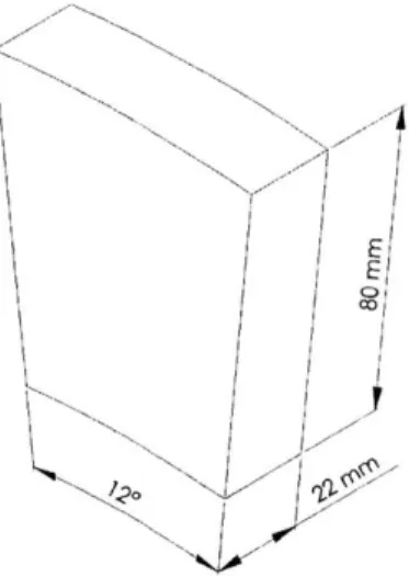
The magnet rotors serve to support the permanent magnets between the power rotor and the stator. It was determined that the optimal combination of manufacturability and function would be obtained with magnets shaped as 22 mm thick sectors of an annulus, with inner radius of 270 mm, outer radius 350 mm, and spanning 120, as shown in Figure 2-1.
C/1CO
Figure 2-1: Shape of Permanent Magnets
In the assembled state, the attractive forces acting on each magnet are approximately balanced between the power rotor core and the stator core, so the magnet rotors are not required to support substantial axial loading. As described in Section 2.5, the unbalanced forces encountered during assembly will be supported by other means. Thus, the magnet rotor plates are aluminum discs 22 mm thick, with windows slightly larger than the magnets machined into the active region of the machine. The magnets are then retained in the magnet rotor by the combined action of a thin (1 mm thick) aluminum faceplate on each side and epoxy filling the remaining space in the windows.
The part drawing from which the magnet rotor plates were machined is shown in Fig-ure A-2. As in the power rotor plates, an array of holes allow for axial ventilation to flow through the magnet rotor to reach the innermost air-gaps. Due to a mistake in manufac-turing, twenty evenly spaced holes were drilled instead of the specified eighteen, but the impact on airflow and structural strength will be negligible.
The magnet rotors must spin independently of the other elements of the machine. They are designed to fit a bearing in the center which bears on the main driveshaft. The two magnet rotors should, however, rotate at identical speeds, so it is reasonable to connect them together. Connecting the magnet rotors with a hollow free-wheeling shaft simplifies the problem of axially constraining the magnet rotors. Thus, six holes around the periphery of the bearing mount allow bolting to such a hollow shaft and serve the additional function of securing a locator plate to constrain the bearing.
2.1.3 End Plates
The end plates serve a number of ancillary functions in the machine. Primarily, they support the weight of the driveshaft and constrain it against axial motion with respect to the housing. To this end, each has a hole in which to mount a bearing for the driveshaft and bolt holes at the outer radius to attach to the housing, as shown in the part drawing, Figure A-3.
The end plates additionally serve as mounting points for the slip-ring brushes and ven-tilation system (see Section 2.4.2 and Section 2.4.3, respectively). At the time the end plates were designed, the details of the slip-ring and ventilation systems were not known, so no provision for them was included in the part drawing. The expectation was that it would be simple to modify the end plates to accommodate the mounting requirements of the slip-rings and ventilation system.
2.1.4 Housing
The housing of the machine serves to hold the stator in place and provides a means of attaching the machine to the test-bed. Thus, the housing bears the entire torque-load of the machine, but at a large radius, so that the required material thickness is fairly small. The housing must transfer the weight of the machine to the test-bed mounting points, and provide attachment points for the end plates.
Original Housing
The original design of the housing was manufactured according to the part drawing of Figure A-4. The housing design has slots to allow airflow to escape radially from the air-gaps of the machine. Twenty mounting holes are provided to allow the stator to be bolted
to the housing. Twenty larger holes interspaced with the stator-mounting holes allow the electrical connections to the stator windings to be brought outside of the case. The end plates mount to ten holes in flanges at each end of the housing.
Revised Housing
Unfortunately, two problems arose after the housing was machined which necessitated a redesign of the housing. First, the wire from which the stator windings were constructed was quite stiff. The stiffness of the wire made it extremely difficult for the wires to be bent to fit out through the provided holes. This problem was compounded by the fact that the actual stator winding form took up more space than was anticipated at the time of the housing design, leaving very little space in which to maneuver the wire ends.
Even more disastrously, it was found that the design of the rotor windings (as described in Section 2.3.2) required about a centimeter more radial space than was available in the
housing. Because the design of the windings was dictated by geometric concerns alone, available housing space was not considered, and the interference between windings and housing was not discovered until after the windings had been manufactured.
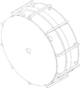
Given these problems, it was determined that the simplest solution was to redesign the housing of the machine. Budget requirements dictated that the new housing be much simpler than the old design. Thus a "skeletal" design was developed. This design consists simply of a rolled-and-welded aluminum ring to hold the stator, and ten aluminum stringers running from the ring to the end plates. The design of the ring is shown in Figure A-6, and that of the stringers in Figure A-7. The assembled housing, including end plates, is shown in Figure 2-2. The cross-sectional area of the stringers is similar to that of the original housing (they are much thicker than the housing wall), so ability to bear the torque loading will not be compromised.
2.2
Magnetic Cores
The overall machine design contains three magnetic cores: two rotors and one stator. These cores serve to transport flux between poles in the machine, closing the flux loops without adding any appreciable reluctance to the magnetic circuit. The cores are made from silicon electrical steel, which has high permeability and relatively low conductivity. The particular
4N
Figure 2-2: Assembled "Skeletal" Housing
steel used is M-19, a medium-grade non-oriented steel, which was determined to be sufficient for our purposes.
The use of permanent magnets in the machine greatly simplifies construction of the cores. The magnets serve to drastically reduce the effect of the air-gap of the machine on its function. Consequently, the coils in the machine may be wound in the air-gap. Winding slots are not needed, as the magnets already constrain the flux to flow across the air-gap.
To prevent the formation of large eddy currents in the cores, which would substantially decrease machine efficiency, the cores have a laminated construction, with thin sheets of steel separated by a layer of insulating coating. The core is tape-wound, which is to say that the required toroidal form is constructed from a single very long strip of steel wound up in a long coil from the required inner radius to the required outer radius. The tape-wound form makes the core construction relatively simple.
The required axial thickness of the cores, and consequently the width of the steel strip, is determined by the expected maximum flux density which the cores must carry. This flux density must be less than the saturation flux density of the steel. For our machine, a rotor thickness of 16.5 mm is sufficient, while the stator, which must carry flux from both rotors, must be 31 mm thick. Thickness of the steel strip is determined so as to be much less than the skin depth in M-19 steel at the electrical frequency of concern: t
<
6 = . Theselected 29 ga. steel has a thickness of about 0.35 mm, which is satisfactory. The steel was ordered with an AISI C-5 insulating coating to ensure insulation between layers.
To reduce the cost from processing overhead, the steel strip was ordered only in 16.5 mm width. Four essentially identical cores were then wound up from the strip, using about 400 m of strip per core. As the strip was shipped in several coils, the strip was spliced together, once per core, during the winding process. The resulting slight discontinuities should have negligible effect on the electrical properties of the cores. After winding, the cores were soaked in a low-viscosity epoxy (West System 105/206) to hold the laminations together.
Due to the relatively uneven nature of the winding form used, the cores were neither perfectly round nor perfectly flat. Furthermore, the nature of the imperfections varied somewhat from core to core. The two most similar cores were selected to be combined to form the stator core. All three core assemblies were then wrapped in 2-inch-wide 9 oz. fiberglass tape, and epoxied again. This has the additional benefit of further ensuring the integrity of the cores, and protecting their surfaces.
Figure B-1 shows a photograph of the cores after the fiberglass wrapping had been applied. Assembly of the cores with the windings and the structural elements of the machine is discussed in Section 2.5.
2.3
Windings
The windings provide the means for electrical interaction between the fields in the machine and the outside world. As such, they are perhaps the most critical element to the operation of the machine. Ignoring for the moment the effects of the permanent magnets, windings on the rotor are responsible for the electrical poles which generate the rotating flux wave in the machine. To ensure a moderately sinusoidal overall flux distribution, three phases of excitation are used on the rotors. Thus, for our 20-pole, dual-rotor machine, there are a total of 120 rotor windings. Stator windings are then responsible for linking the rotating flux wave generated on the rotor, and thereby producing voltage at the output terminals of the machine. The stator is a 3-phase system for similar reasons, and thus there are a total of sixty stator windings per active face.
2.3.1 Stator
The stator windings are responsible for the majority of the power handling capability of the machine. Consequently, in our design, they are constructed from 7 x 1.25 mm flat litz wire (SF2 transpose). Litz wire is used to overcome skin-effect-induced resistive losses in the windings due to the 60 Hz alternation of the current in the windings. The total copper cross-sectional area (860 mm2) was chosen to be sufficient to carry the target output power of about 10 kW. The rectangular cross-section of the wire simplifies the winding operation. The stator interacts with a rotor on both of its axial faces,1 so the stator windings must cover both axial faces of the stator. This is most simply accomplished with a Gramme-Ring winding, in which the windings wrap all the way around the rectangular cross-section of the toroidal stator. Current flowing in a given direction in some stator winding will thus flow radially inward along one axial face of the stator, axially across the inner radial face, radially outward along the second axial face, and axially back across the outer radial face. This has the advantage of creating both face windings with a single relatively short pair of end-turns.
Each of the individual stator windings is composed of 10 turns of wire in 2 layers. The end-turns were formed around half-pieces of 1-inch diameter acrylic rod, to keep the bend radius high at the corners of the stator cross-section. After winding, the coils were clamped in place and epoxied to each other and the core. The whole structure was wrapped in fiberglass tape and epoxied again to protect the windings. Figure B-3 shows the structure with the fiberglass wrapping partially complete.
Measurements
Before the stator was wrapped in fiberglass, its electrical characteristics were tested. This was done by applying a 60 Hz sinusoidal voltage across one phase of the winding. This voltage was produced with a variable transformer (variac) from one phase of a 3-phase supply. The current and voltage waveforms were then measured using an oscilloscope with appropriate probes. This test was carried out for 4 voltage amplitudes: 75, 100, 150, and
200 Vrms.
'Where faces are specified as axial, radial, or circumferential, the direction refers to the direction of a normal vector to the surface.
0.46 0.4- -04 - -- --. -.- -.- -.- -.- -.-- --.-. -. .-- - 0.2-E X 2 < -0.2 -. . .. . . -0.4--0.6 - -...-... -0.8 I -500 -400 -300 -200 -100 0 100 200 300 400 500 Approximate H, Ampere-turns
Figure 2-3: Stator B-H Characteristics for 100 Vrms 60 Hz Sinusoidal Drive
An approximation of the hysteresis loop of the core can be obtained by plotting applied volt-seconds (the integral of the input voltage) against terminal current. The resulting curve for 100 Vrms is shown in Figure 2-3. The field intensity in the core is then approximately
H = Ni, and the flux density B f , where A, is the cross-sectional area of the core.
Note that to the extent that the winding resistance is significant v > dA and thus we have overestimated the flux density in the core. A plot of the approximate hysteresis loop for the 100 Vrms excitation is shown in Figure 2-3.
The curve of Figure 2-3 allows determination of the saturation field and flux of the core, along with the remanent magnetization and the coercivity of the material. We can read
Bsat
e
0.5 T, which is fairly low. This corresponds to a useful drive limit of about 1 Vs.The field at Bsat is about Hsat ~ 150 A. Finally, the hysteresis parameters are H, - 100 A, and B, ~ 0.4 T.
2.3.2 Rotor
The required power level of the rotor windings is much lower: less than 1 kW for our expected range of slip. The rotor windings are thus constructed of standard 16 AWG magnet wire. The electrical frequency at the rotor is the slip frequency, which will be much lower than 60 Hz, so skin effect is not important in the rotor windings.
In contrast with the stator, which interacts on both axial faces, the rotor interacts on only one axial face, and consequently only needs windings on that face. Although it would be possible to use a Gramme-Ring winding pattern on the rotors as well, more wire is used by a Gramme-Ring winding than conventional end-turns. Conventional end-turns thus offer lower resistance and consequently higher efficiency. Additionally, securement of the rotor core to the power rotor plate will be stronger if there is no wire between them. With conventional end-turns, all of the wire remains in the plane of the rotor's axial face. Current in a given winding runs radially inward at one pole, crosses to an adjacent pole at the inner radius, flows radially outward at that pole, then crosses back to the first pole at the outer radius. The difference between the two winding schemes is visible in the assembled core photos of Figure B-3 and Figure B-5.
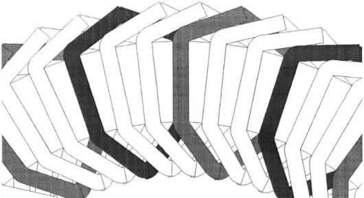
Although the conventional end-turn pattern improves efficiency, it introduces a geomet-ric problem: how to physically arrange the end-turns of different phases. Our machine uses a non-consequent-pole design, which means that in any given bundle of wires traversing the core face (what would be a slot if our machine had slots), there are two windings, one above and one beneath. If the windings are to neatly lie flat, the end-turns traversing from bundle to bundle in phase A must pass four other end turns corresponding to the two bundles from phases B and C lying between the phase A bundles. Conceptually, this can be solved if the end turns from A to A' pass above the end-turns which come from the bottom windings in the intervening B and C bundles, and below the end-turns which come from the top windings.
If the windings are to be symmetric, this suggests a hexagonal footprint, so that the nearly-parallel top- or bottom-winding end-turns do not interfere with each other. A schematic representation of the winding plan is shown in Figure 2-4.
Two layers of 12 turns of 16 AWG wire were determined to appropriately fill the axial face of the core. The geometry problem associated with finding appropriate angles and side-lengths for the hexagon produces bend angles at the inner and outer ends of the active legs of the winding of 35' and 65' respectively. Two forms were constructed having a hexagonal center spacer of appropriate angle and side length, and a height of about 0.11 in. to accommodate two 16 AWG wires side by side. By splitting the form in half and displacing the halves vertically with respect to each other by about 0.11 in. the winding was constrained
Figure 2-4: Schematic Representation of Rotor End-Turn Configuration
The form was affixed to an aluminum mandrel to allow it to be turned by a lathe, and the wire fed by a combination tensioner and electronic turn counter. Forms could then be tightly and fairly uniformly wound with the required 24 turns in about 30 seconds. The top half of the form was divided into thirds. Each third was then removed one at a time, and the underlying winding epoxied with an epoxy gel. Piecewise gluing was required to prevent springback in the winding from destroying the coil, as it would if the entire top half of the form were removed at once. Unfortunately, the overhead associated with preparing a coil for winding and gluing it after winding was sufficiently long that only two forms could be run in parallel, and the process was quite slow as a result. Figure B-2 is a photograph of the winding apparatus.
Measurements
The 120 rotor windings were tested on an impedance analyzer in 2 batches of sixty. The objective of this testing was to ensure that none contained a shorted turn, and that all had approximately the correct number of turns. A shorted winding turn would be disastrous, but coils having 23 or 25 turns would not appreciably affect the operation of the machine, especially if appropriately balanced around the machine. From the inductances of the coils, it was possible to detect shorted coils and coils with too few turns. One coil was found to
have a shorted turn, evidenced by an inductance too low by half an order of magnitude. A histogram of the inductances of the coils after replacement of that coil is shown in Figure 2-5.
Winding Inductance Distribution 35 30-25 - -- -- - - 20-1 0 - .. . . . . . . . .. 5-0 6 95 100 105 110 115 120 125 130 135 140 145 Normalized Winding Inductance, pH
Figure 2-5: Histogram of Rotor Winding Inductances, First Pass
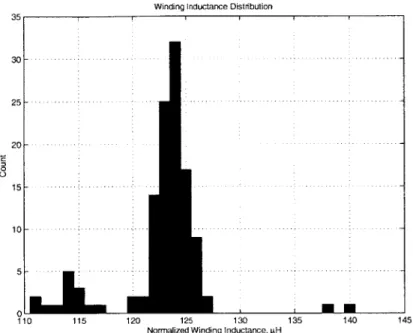
In Figure 2-5, the coils clearly clump into groups whose centers correspond well to the expected inductances of coils with numbers of turns ranging from 21 to 25. Four coils can be seen to have fewer than 23 turns, and these coils were also replaced and the replacements tested. The final inductance distribution is as shown in Figure 2-6. In this distribution, there are 14 coils with 23 turns, and 2 with 25. If the coils with 25 turns are matched pairwise with 23-turn coils, the effects of the two will essentially cancel out, leaving 12 coils short a turn to distribute about the machine. Conveniently enough, these 12 coils can be evenly distributed among the 3 phases and physically about the machine by placing them at locations 1, 11, 21 ... 101, 111, where the 60 coils of the first rotor are numbered sequentially around the rotor from 1 to 60, and those of the second rotor from 61 to 120.
2.4
Other Parts
A few other miscellaneous parts are necessary to the function of the machine, none of which have been fabricated as of this writing. This set of parts includes the shafts, slip-rings, ventilation system, and mounting hardware. This section briefly discusses the requirements
Winding Inductance Distribution 35 3 0 - -.-.-.-.-.-.-.--.--2 5 - - - - - -.-.-.-.- -20 -0 01 110 115 120 125 130 135 140 145
Normalized Winding Inductance, paH
Figure 2-6: Histogram of Rotor Winding inductances, Second Pass
of each part and outlines possible designs. Fabrication of these parts, assembly, and testing of the machine are the bulk of the further work described in Section 5.2.
2.4.1 Shafts
The 2 shafts in the machine cannot be produced until final dimensions of the machine are known. Due to the inaccuracy of some of the details of the assembly process, these dimensions are not yet known. The specifications of the shafts and their dimensions as a function of the as-of-yet-unknown machine dimensions are examined in turn.
Driveshaft
The driveshaft serves to transmit torque from the external prime mover to the power rotors of the machine. To sustain 10 kW at a nominal synchronous speed of 360 rpm requires a torque capability of about 265 N m. Given such a substantial load, the shaft must be made from a reasonably high-grade steel alloy. Converting the analysis of
[1]
to metric units indicates that the minimum shaft diameter should be 30 mm. The shaft must also bear the substantial axial load associated with supporting the power rotors against the attractive force of the permanent magnets. This may be accomplished by a shoulder onthe shaft stepping up to a 45 mm diameter. Appropriate bearings for these shaft diameters have already been purchased (to measure for fit into the endplates and magnet rotors). One more shoulder on the shaft is required to locate the permanent magnet rotors, but the anticipated loading is quite small, so the next easily available steel rod diameter-probably 2 in.-should be used. Overall form of the driveshaft is then as shown in Figure 2-7.
Figure 2-7: Driveshaft Plan View
The distance between the inner shaft shoulders should be set as given in (2.1), and between the outer shoulders as in (2.2).
di = ts + 2g + (tmr, - t1) + (tr2 - 2) - 2tb (2.1)
do = ts + 4g + tmri +tpcl + tmr2 + tc2 (2.2)
In (2.1), t, is the total stator thickness including windings, g is the desired operating air-gap, tmr is the thickness of the magnet rotor, including faceplates, tf is the thickness of a
magnet-rotor faceplate, and tb is the axial length of the magnet-rotor bearings. In (2.2),
tpc
is the thickness of the power rotor core, measured from the winding face to the surface of the power rotor plate, in an assembled state. Numerical subscripts are used to indicate the fact that it should not be assumed that thicknesses are identical for nominally symmetrical parts. The distance tmr - tf should be almost exactly 23 mm for both magnet rotors, andtb = 19 mm.
The keyways in the shaft should be machined 5 mm wide, 2.5 mm deep, and 45-50 mm long to accommodate standard square keys which interface properly with the power rotor plates.
Free-Wheeling Shaft
The free-wheeling shaft mostly serves to help locate the magnet rotors with respect to the shaft, and thereby the rest of the machine. As such, it is not expected to bear substantial axial or torque load. The free-wheeling shaft must have an internal diameter sufficient to be well clear of the outer diameter of the driveshaft. The outer diameter of the shaft should be at least 4.75 in. ~ 120 mm to allow mounting to the magnet rotors. Mounting to the magnet rotors will be most simply accomplished if 6 holes are drilled and tapped to fit an M6xl.0 screw in the ends of the shaft. In principle, there is no reason that the function of the free-wheeling shaft cannot be accomplished with 6 standoffs with threaded holes in their ends. Using 6 standoffs is attractive for cost reasons, but care must be taken that the
standoff lengths are very well matched to avoid skewing the rotor plates.
Regardless of the nature of the free-wheeling shaft, its length should be as given in (2.3).
1 = ts + 2g (2.3)
Included in the free-wheeling shaft assembly should be locator plates for the magnet-rotor bearings. These plates should be annular in form, with an inner diameter of 80 mm, an outer diameter of at least 120 mm, and thickness on the order of 2 mm, with holes drilled to align with the six mounting holes in the magnet rotors. These plates then lie against the outer faces of the magnet rotor plates and are held in place by the same bolts which secure the free-wheeling shaft.
2.4.2 Slip-Rings
The slip-ring assembly connects the rotor windings to an external source of excitation current for the rotor windings. This is accomplished with a set of conductive rings mounted to the shaft and connected to the rotor windings. Spring-loaded carbon brushes are affixed to the case and are held against the conductive rings, making a rotating contact to the rotor windings. The number of rings in the set of slip-rings determines the variability of the rotor connection topology. The most general configuration requires 12 rings, one for each end of each phase on each rotor. Such a scheme would allow the the rotors to be configured in either a A- or Y-connection, and for the 2 rotors to be connected in series or parallel.
Unfortunately, it is somewhat difficult to run wires from the rotors to the outside of the machine. Thus, if the most logical scheme of locating all of the slip-rings on the outside at one end of the machine is followed, wires from the far rotor will have to travel under 3 bearings to reach the slip-rings, and as such it is desirable to limit the number of wires needed.
Fixing the configuration of the far rotor as a buried-neutral Y-connection and bringing out all 6 ends from the near rotor seems a reasonable compromise. This allows the mini-mum number of wires (3) to transit under the magnet-rotor bearings, but still allows some variation in the overall configuration. This scheme is especially attractive if the slip-rings are located on the end of the machine opposite the prime mover, as the driveshaft is not required to transmit any torque at the point that the 9 wires must pass under a bearing. The shaft may therefore be drilled out ("gun-bored") from the slip-ring end, and the wires run along the center of the shaft to the slip rings. Such a scheme is not practical for the far rotor for two reasons. Firstly, the required length of drill to reach the far rotor is pro-hibitive. Secondly, gun-boring the shaft might easily compromise its ability to bear the required torque load, given the weakening effect of the keyways.
It is worth noting that by having two distinct sets of slip-rings, one for each rotor, and affixing these slip-rings to the inside of the endplates instead of the outside, it is possible to avoid passing the rotor wires under any bearings. It may be infeasible to use such a slip-ring design due to the additional space required inside the machine, but the benefits are sufficiently attractive to merit careful consideration.
2.4.3 Ventilation
Some amount of ventilation is required to keep the temperature of the cores and wiring of the machine within reasonable limits; a maximum temperature of 850 C should allow all of the insulations and epoxies to operate within specified limits. With the original housing design described in Section 2.1.4, the intended method of cooling was to mount a blower to each endplate. Air would then be forced axially through the center of the machine to the air-gaps, where it would flow radially outward through the air-gaps and then through ventilation slots in the housing. Airflow around the exterior of the power rotor plates would be prevented by a simple plastic rotating seal against the outside of the power rotor plates.
With the new skeletal housing design, this scheme is more difficult to enact. However, an extension of the plastic-rotating-seal concept can likely be used. An annulus of thin flexible plastic (preferably polyethylene sheet) mounted to the inside of the endplates such that it will touch the outer surface of the rotor plates may be used. The thin film would then be held against the outer surface of the rotor plates by the positive pressure created by the blower. Although the resulting seal would not be very good, all that is required is that leaking through the seal be a higher-resistance path than flowing out through the air-gaps. As per the thermal analysis of [1], an airflow of 0.05 m3/s per air-gap will cause a temperature rise of approximately 20 K. Given the number of approximations required to obtain such an estimate, a factor of three below the desired maximum temperature rise seems wise. Thus, if two blowers are used (one in each endplate), each should have a rating of approximately 0.1 m3/s ~ 200 CFM.
2.4.4 Mounting and Testbed
The machine must be mounted to a test-bed so that its performance can be analyzed and the validity of the models of Section 3 ascertained. Our intended test facility is a large dynamometer which was donated to the lab by the Ford Motor Company. The dynamometer is rated at 20 horsepower over a range of 575-4000 rpm. Interfacing with the dynamometer has two aspects: mounting and torque transmission.
Mounting
The housing of the machine must be secured to the test facility. The currently-intended method of attachment is to attach 3 aluminum "feet" to the ring in which the stator is mounted. These feet would bolt to the outer radial face of the ring and be of appropriate length to support the machine in a level state. These feet would then bolt to an aluminum block whose height is determined by the requirements of the transmission between the dynamometer and the machine. The block would then bolt to the dynamometer baseplate.
Torque Transmission
The minimum specified speed of the dynamometer is 575 rpm, and its shaft is closer to the baseplate than the radius of our machine. Thus, some form of transmission is required between the machine and the dynamometer.
The transmission should likely be a toothed belt and two sheaves in a 2:1 diameter ratio. The diameter difference will allow the machine to run at its nominal synchronous speed of 360 rpm while the dynamometer runs at 720 rpm. The offset between the two sheaves can also be used to allow the machine shaft to be considerably higher than the dynamometer shaft. It is likely that a tensioning idler will be required to get the necessary torque transmission between the two. Details of the transmission depend very heavily on the availability of sheaves and belts appropriate to the connection, so the design is not pursued further here.
2.5
Assembly
Assembly of the machine requires careful consideration due to the large static and dynamic axial forces in the machine. At the time of this writing, relatively little assembly beyond what has already been described is completed. The individual components have largely been constructed, but they have yet to be interfaced.
2.5.1 Power Rotors
Both of the power rotor cores have been secured to their respective power rotor plates, and one of the sets of windings has been affixed to its core. As mentioned in Section 2.1.1, the original mounting scheme for the power rotor cores required constraining the cores with U-bolts over the top of the core. Difficulty in obtaining appropriate U-U-bolts made this scheme less attractive. Furthermore, the nature of the rotor windings left little available space on the axial surface of the core upon which the U-bolts might bear.
As specified in [1], the U-bolt attachment scheme would result in a larger-than-necessary structural safety margin for the attachment. Thus, it was possible to revise the attachment mechanism to simultaneously resolve both concerns with the U-bolts. The solution chosen bolts the core directly to the power rotor plate with standard socket-head cap screws. To prevent interference between the heads of the bolts and the windings, the holes in the core are counterbored.
In this application, it is not feasible to use flat-head screws and countersunk holes due to the laminar construction of the core. The glue-joint between laminations in the core is fairly weak, even though the overall structure is reinforced with fiberglass. Thus, there is substantial concern that the conical head undersides of flat-head screws would force the
laminations apart under heavy load, and cause disintegration of the core. The flat underside of socket-head cap screws and attendant flat bottom of appropriately counterbored holes do not provide any means of transferring lateral force to the core, and therefore do not engender this concern.
The attachment used 18 evenly spaced 65 mm M6xl.0 grade 12.9 socket-head cap screws, all radially centered in the core. The high grade steel of the screws is necessary, given the expected loading. The screws were all tightened to a torque of 16.9 N m, approximately the maximum recommended tightening torque. This gives an expected bolt preload of 15.6 kN, which should be sufficient that the joint does not come out of compression under any expected loading. If the joint were to leave the compressive regime, the comparatively small but not insignificant alternating force load on the bolts during operation could easily lead to fatigue failure of the bolts, which would be disastrous.
With the cores appropriately secured to the plates, all that remains to be done in assembly of the power rotors is attachment of the windings. At present, this has been accomplished for one of the rotors. Windings were laid out on the surface of the core, in a distribution as described in Section 2.3.2. The coils were then wired and soldered together with all of the coils in a given phase in series, appropriately alternating in sense. After soldering and insulating the joints, continuity of each phase was tested, and DC isolation between phases was tested by applying ±400 V between each pair of phases.
Following the electrical tests, a relatively small amount of epoxy was spread over the top of the windings, securing them weakly to each other and the core, and the whole structure was clamped with a large aluminum sheet above to flatten the windings into place. Further attachment was then accomplished with a layer of fiberglass tape spread over the exposed windings to protect and secure them. The fiberglass tape was liberally soaked in epoxy, then similarly clamped.
2.5.2 Stator Mounting
The structure mounting the stator to the housing need sustain relatively little torque, trans-verse (gravitational), or axial load in operation. However, during assembly, the attachment will have to support the full attractive force between the stator core and the permanent magnet rotors. It is intended that this load be borne by L-shaped spacer blocks which sep-arate the stator from the mounting ring of the new housing design. These L-shaped blocks,
shaped as shown in Figure 2-8, would lie around the periphery of the stator between the sets of three windings corresponding to poles.
Figure 2-8: Form of Stator Support Blocks
Space of about 0.75 in. has been left between the phase A winding of each pole and the phase C winding of the adjacent pole. By alternating the axial direction of the spacer blocks, the stator can be effectively constrained from motion in the axial direction by ten blocks each way. Constraint from rotational or transverse motion is trivially satisfied as long as the blocks are somewhat securely attached to the core and the ring.
2.5.3 Final Assembly
The majority of the remaining physical difficulty of creating the machine will lie in the final assembly of the various components. During assembly, the full attractive force of the permanent magnets will be at issue several times. Worse yet, at several stages in assembly, components whose attractive forces are roughly balanced in the assembled machine will have to bear the full attractive force in one direction.
Furthermore, some consideration will be required to allow careful positioning of elements which, due to the magnets, will be attracted to each other with a force on the order of 50 kN. Thus, a screw-jack must be constructed to lower the elements together in a controlled fashion. The simplest method of construction would be to use a stiff, thick plate of diameter larger than the machine diameter. Three locations around the edge of the plate would then have standoffs aligned to bear on the ends of the stringers in the housing. Necessarily,
these standoffs would not be perfectly symmetrically placed, as there are ten stringers in the housing structure.
The plate would also have three symmetrically placed holes at a smaller radius, through which large threaded rods (perhaps 0.75 in. diameter) could pass. Affixed to the ends of the threaded rods would be hooks, to which steel cables could be attached. On the top side of the plate, a nut and washer on each rod would bear on the surface of the plate. Thus, by loosening the nuts, the threaded rods, bearing the load of an element under assembly,
could be extended in a controlled manner.
To lower one of the rotors into place, steel cables would be run from each hook, through the ventilation holes in the plate, and back to the hook. Thus, after the rotor was in place, the cable could be pulled back through the holes without substantial difficulty. If thin plastic spacers are inserted into the air-gaps before assembly, they would then support the attractive loading after the cable and screw-jack were removed. Once the machine is completely assembled, the plastic spacers would be pulled out.
A likely appropriate order of assembly would be as follows.
1. Stator and housing (not including end plates) assembled and stood on one end (axial direction vertical).
2. Magnet rotor A lowered into place over stator. 3. Free-wheeling shaft attached to magnet rotor A.
4. Power rotor A lowered into place over magnet rotor A , taking care that the two are well aligned so that the driveshaft fits both.
5. Endplate A secured to housing, aligning for shaft fit again. 6. Assembly flipped over.
7. Driveshaft inserted.
8. Magnet rotor B lowered over driveshaft.
9. Free-wheeling shaft attached to magnet rotor B. 10. Power rotor B lowered over driveshaft.
11. Endplate B secured to housing. 12. Testbed mounting hardware attached.
Chapter 3
Analysis and Modeling
If results from measurement of the prototype are to be usefully understood, a model of the machine must first be developed which creates a context for the measurements. Moreover, the nature of the measurements performed will be dictated to some extent by the model of the machine. Finally, to obtain the desired end-behavior, a control circuit must be built. Controller design is considered in Chapter 4. However, it is not possible to design a controller, or even adequately describe the aims of one, without first developing a dynamic model of the machine.
It is therefore clear that some effort must be expended in development of models of the machine, and that is thus the aim of this chapter. A general understanding of the operation of the machine and its steady-state behavior are developed in Section 3.1. Based on these concepts, Section 3.2 then constructs a full-blown tenth-order model of the system dynamics and considers some simplifying assumptions which may be appropriate depending on the desired results.
3.1
Steady-State Behavior
The analysis of our machine topology is simplified by the fact that direct interaction between the rotor and stator windings is very weak in comparison to interaction with the magnet rotor. A quick verification of this assumption can be made by comparison of the peak flux-densities due to the magnets and currents in the stator, measured at the rotor.
The magnets in the machine are neodymium-iron-boron (NdFeB) material, and as such have a remanent flux density Br ~ 1.3 T. For an air gap which is relatively small compared
to the thickness and lateral dimension of the magnets, the flux density at the other side of the gap can be approximated as given in (3.1), where tm is the magnet thickness, and g is the air-gap thickness.
B Br tm ~ 0.9 T (3.1)
g + tM
Peak flux density due to stator winding currents can be estimated as by assuming the gap to be relatively small compared to the pole spacing and applying standard approximations. Firstly, from the point of view of excitation from the stator, the entire structure of the magnet rotor has permeability of
po,
so the effective air gap is the entire distance from the stator iron to the power rotor iron. Thus, the gap is not in fact small, so our calculation will therefore err on the conservative side and overestimate the flux density. Given the relative permeabilities of the core and the air gap, we can assume that the field intensity H is only non-zero in the air-gap. For a small gap, the field in the gap will be constant and directed strictly across the gap. Thus Ampere's law for a contour enclosing one stator coil and traversing straight across the gap gives f H - dl = 2gHg = NJI. Solving for Hg, wecan then determine B, using a conservative stator heating limit of NJ,8 < 1000 A.
B < g < 15 mT (3.2)
-
2g-Comparison of (3.1) and (3.2) shows that the stator currents have more than an order of magnitude less effect on the power rotor than do the magnets. Thus, we are justified in the approximation that each set of windings interact only with the magnet rotor.
In the reference frame of the power rotor, the behavior of the magnet-rotor is equivalent to that of a permanent-magnet synchronous motor. That equivalent motor is then loaded by a torque derived from the interaction of the stator and the permanent magnets. The motor runs in synchronicity with the electrical frequency of the power rotor. Thus, in the reference frame of the stator, the motion of the magnet rotor is that synchronous rotational speed plus the speed of rotation of the rotor reference frame, which is the shaft speed. The interaction between the magnet rotor and the stator is equivalent to a permanent magnet synchronous generator in which the shaft speed is the same as the magnet rotor speed.