A DEVICE FOR OBJECTIVE MEASUREMENT OF SPASTICITY
by EDDY BARAK
B.S. WAYNE STATE UNIVERSITY (1975)
Submitted in partial fulfillment
of the requirements for the
Degree of Master of Science
at the
Massachusetts Institute of Technology
September 1977
Signature of Author
(
Departmei ' ieonautic and Astrontautics
11/1
Auainst 22, 1977Certified by
(rThesis Supervisor
Accepted by
Document Services Room 14-0551 77 Massachusetts Avenue Cambridge, MA 02139 Ph: 617.253.2800 Email. [email protected] http://libraries.mit.edu/docs
DISCLAIMER OF QUALITY
Due to the condition of the original material, there are unavoidable flaws in this reproduction. We have made every effort possible to provide you with the best copy available. If you are dissatisfied with this product and find it unusable, please contact Document Services as soon as possible.
Thank you.
Some pages in the original document contain pictures,
A DEVICE FOR OBJECTIVE MEASUREMENT OF SPASTICITY *
by EDDY BARAK
ABSTRACT
Spasticity is a neuromuscular disorder, due to lesions of the central nervous system, and is characterized by hypertonus, hyperflexia and clonus. Clinical
assessment of spasticity is important to evaluate the efficiency of chemo-and physical therapeutic treatment of spastic patients. At present,
evalua-ti*on is made based on ill-defined and highly subjective methods, which lead
to differences of opinion among clinicians. It is difficult, if not impossible, to obtain a quantitative estimate of the changes effected in the patient's
condition for comparison with subsequent examinations. Therefore, a reliable and objective means for clinical measurement of spasticity and other
neuro-muscular disorders has been developed.
A foot manipulator, that rotates the foot about the ankle joint in a programmed
manner, was designed and built. The device is controlled and monitored by a digital computer that records four parameters of interest: position, torque,
tibialis EMG, and soleus EMG.
The system is capable of performing three basic types of movement: ramps,
sinusoids and triangular displacements.
A preliminary evaluation of the new design has been done on a pool of normal
subjects and on two patients having clinical evidence of "spasticity". Dif-ferent velocity ramps, sinusoids and triangular movements were introduced with a variety of instructions given to the subjects. The results were found to be consistent, highly reproducible and in agreement with previously reported
physiological phenomena. Performance of the device attests to the satisfaction of the design objectives and demonstrates the system's usefulness for appli-cation in various physiological investigations performed at the ankle.
* This work was performed as part of the requirements for the degree of Masvter of Science at the Massachusetts Institute of Technology, and was
I wish to express my sincere thanks to my Supervisor, Professor Laurence R.
Young, for granting me the honor of being a member of his research group and for his encouragement throughout this work.
I am very grateful to Dr. Greg L. Zacharias for his guidance in establishing a new perspective of the nature of the universe through the spectacles of
control theory. I thank him for his patience in teaching me how to use the Lab's computer and helping me with the programming.
Many thanks go to George F. Dalrymple of the Sensory Aids Research Facility
for showing me electronic magic.
Special thanks go to Dr. Sheldon Simon of the Gait Analysis Lab at Children's Hospital Research Center for his valuable advice, criticism, encouragement,
and sense of humor, and to Dr. Mark Hallett of the Neurology Department of Peter Bent Brigham Hospital, whose enthusiasm provided a sense of excitement
and accomplishment.
I am grateful to Dr. Lindesay Harkness, a visiting student from Oxford, for her cheerfulness and moral support in times of stress.
I am indebted to Mrs. Sherry Modestino and Mrs. Kerry Campbell for the fine and excellent way they handled the thankless job of typing the manuscript. Special thanks are due the experimental subjects and, in particular, the
patients JWF and JJD.
Above all, I wish to express my deepest appreciation to my wife, Dorothy, whose patience, understanding, encouragement, participation and devotion has made everything possible. I dedicate this thesis to her.
This research was supported by a grant from the Department of Health, Education and Welfare Rehabilitation Services Administration, #23-55854.
4
TABLE OF CONTENTS
Chapter Page
I Introduction 5
1.1 Background
1.2 Clinical features of spasticity - a brief review
1.3 Related research
1.4 Previous research done at the MVL
1.5 Objectives of this thesis 1.6 Outline of this thesis
II TWISTER - An Electromechanical Foot Manipulator 13
2.1 Introduction
2.2 Mechanical structure
2.3 The electromechanical servo mechanism
2.4 Electromechanical transducers
2.5 Safety mechanisms 2.6 Man machine interface
III Computer Control and Data Analysis 37
3.1 On-line computer control and data acquisition 3.2 General organization of "TWIST" program 3.3 Data processing
3.4 Plotting and displaying the data
3.5 Calibration
IV Normal Subject Experiments 47
4.1 Introduction
4.2 Experimental protocol
4.3 Experimental results 4.4 Summary
V Spastic Subject Experiments 67
5.1 Introduction.
5.2 Experimental Results
5.3 Summary
VI Summary, Conclusions and Recommendations 79
6.1 Summary
6.2 Conclusions 6.3 Recommendations 6.4 Further research
Appendices
A Components and Parts Drawings 85
B Computer Programs 94
C Relative Equivalent Damping 112
CHAPTER I INTRODUCTION
1.1 Background
Spasticity is a neuromuscular disorder of muscle tone due to lesions of the
central nervous system. It afflicts victims of upper motor unit damage such
as spinal cord trauma, stroke and a number of congenital diseases referred
to as cerebral palsy.
Clinically, the term is used to describe a combination of the following
symp-toms: increased muscle tone, i.e. increased resistance to lengthening (hyper-tonus), exaggeration of the passive stretch reflex, increased deep tendon
reflexes (hyperreflexia), repetitive contractions in response to suddenly applied, but sustained, stretch of muscle (clonus) and the "clasp knife"
phenomenon with sudden "melting" of resistance.
A considerable amount of effort, time and money is being devoted to
chemo-and physical therapeutic treatment of spastic patients. Highly touted drugs surface perenially and are being used. New physical therapy programs are
continuously being proposed and implemented. Neurosurgical and orthopedic
procedures to relieve spasticity have been applied. Three common operations
used to date are cutting nerves to prevent impulses from reaching muscles, cutting tendons of the spastic muscle and elongating them, and shortening
the opposing muscles. In spite of all this, there is considerable difference of opinion among clinicians as to whether or not these efforts have any real beneficial effects on the patients. One fundamental reason for this
situa-tion has been the lack of an objective measurement, as well as ill-defined methods for evaluation.
Usual clinical assessments are based on a variety of wholly or partially sub-jective evaluations by physicians, therapists, nurses, social workers, and, of course, the patients themselves. Bias and unreliability of such evaluations
is inevitable. For example, currently, to evaluate spasticity, an examiner holds one limb segment in a fixed position and moves the attached segment passively, noting the muscular resistance he encounters. It is impossible for the examiner to standardize the speed , force or arc of the movement, or to record and quantify the various variables such as the position, resis-tance encountered and the electormuscular activity and timing of the events. This may make it difficult, if not impossible, to retain the impression for comparison with subsequent examinations. The present clinical methods are
therefore very subjective and highly variable since they depend not only on the state of the patient but also on the state of the examiner. Considering the energy involved, both physical and mental, a more reliable and objective means of clinical evaluation is sorely needed.
1.2 Clinical Features of Spasticity - A Brief Review
In general, gross spasticity is manifested by the state of the arm and leg of a patient with upper motor lesions (corticospinal tract). The leg is
6
stiffly extended and resists passive flexion. The arm is held flexed and
resists passive extension. Tendon reflexes are hyperactive and clonus may
be evoked if the stretch is maintained. In the upper limb, spasticity
effects mostly the flexors of the fingers, wrist and elbow, and to a lesser
extent the extensors of the elbow and adductors of the shoulder. In the
lower limb, it effects primarily extensors of hip and knee and plantar flexors of the ankle (triceps surae).
The terms "spastic" and "spasticity" have become such a habitual part of the neurological jargon that no one is expected to define them. But for the
engineer, a proper definition is essential to be able to establish the design criteria. Dorland's Medical Dictionary defines spastic:
"1. Of the nature or characterized by spasms. 2. Hypertonic, so
that the muscles are stiff and movement awkward." and spasticity:
"A state of increase over the normal tension of muscle, resulting in
continuous increase of resistance to stretching."
In the neurological literature (Landau, 1974), there are at least six varieties of spasticity that can be discriminated in this context:
1. SpasticitYPRR (Proprioceptive Reflex Release)
Quiescent unstimulated muscle with increased proprioceptive reflexes, including,
in various degrees, increased phasic tendon jerk reflexes, tonic stretch
reflexes, and the tonic clasp-knife reaction.
2. SpasticityGRR (Generalized Reflex Release)
Reflex release including not only proprioceptive but also and especially polysynaptic flexion reflexes, e.g. the flexor spasms of chronic paraplegia.
3. SpasticityUMNS (Upper Motor Neuron Syndrome)
The entire upper motor neuron complex syndrome, including motor performance disability as well as reflex release, e.g. spastic paraparesis.
4. SpasticityDR (Dystonic - Rigid State)
A spectrum of ill-defined dystonic and rigid states of many origins and pathological features, all characterized by some degree of involuntary
continuous muscle contraction, e.g. athetoid cerebral palsy.
5. SpasticityM (Mixed)
Combination of the above definitions, especially 3 and 4, usually associated
with hemispheral or brain stem lesions.
6, SpasticityU (Undefined)
As can be seen, the lack of clinical ability to define spasticity
compli-cates even more the clinical assessment and evaluation and indicompli-cates the ambiguity surrounding spasticity. This is expected in light of the fact that very little is known about the mechanisms involved in spasticity.
Basically, there are two "types" of spasticity, which are observed in isolated preparations, cerebral and spinal. Cerebral spasticity might occur as the result of severe injury or destruction of some portion of the frontal lobe of the cerebral hemisphere or due to interruption of the pyramidal motor projection of the lobe at the level of the internal capsule. It can be
produced by a variety of causes such as massive hemmorhage, tumor, and,
in children, anoxia or metabolic toxins causing cerebral palsy which occurs
during gestation, parturition or the neonatai period. Cerebral spasticity
can be compared, to some extent, to decerebrate rigidity in animals after midbrain section, primarily affecting the extensors. Spinal spasticity
is produced by lesions (complete or incomplete) of the spinal cord at or
below the level of entry of the eighth pair of cranial nerves. It is
often more severe and irregular than cerebral spasticity. Incomplete
spinal lesions may give rise to more severe spasticity than a complete transverse lesion.
Mild spasticity is manifested in response to rapid passive stretching and it is only towards the end of the movement that some resistance is noticed.
It is believed that the sensitivity of the stretch receptors is augmented
so that tendon reflex can be elicited by a subnormal stimulus, but only the muscles which reflexively contract in the normal subject are involved. In
moderately severe spasticity, resistance to the passive movement is noticed
earlier in the stretching, and the brake action may be so pronounced that the movement is completely stopped. If the stretch is continued, the
resistance suddenly yields. This is autogenic inhibition or the so-called
clasp knife phenomenon. Tendon reflex is not only augmented, but also
radiates to other groups of muscles, including the antagonists. This might
lead to clonus, a state characterized by alternate contraction of agonists
and antagonists.
On the basis of the present knowledge of spasticity, only a few hypotheses attempt to explain the hypothesis [Magoun, 1974; Jansen, 1972; Pederson;
1976]. Current theories agree that spasticity is related to the removal of inhibitory influences acting on the spinal stretch reflex and also to the maintained activity of supraspinal influences that facilitate these reflexes.
Animal experiments have shown that lesions in the corticospinal tract lead to increased facilitation of the gamma motoneurons. This in turn causes
increased sensitivity of the muscle spindles to static and dynamic stretch that leads to hyperactivity of the alpha motoneruon. Increase in firing
rate can lead to contraction of the muscle, i.e. increased muscle stiffness, known as decrebrate rigidity. This occurs in animals after midbrain section.
It is reasonable to compare it with cerebral spasticity in man since both are characterized by extensor rigidity of the gamma type. In the case of
spinal spasticity, the mechanisms involved are more complex since both the alpha and gamma motoneurons may be influenced and there might be effects of sprouti'ng.
8
An attempt to go into more detailed explanations of the present knowledge of spasticity would be far beyond the scope of this thesis and it is left to the interested reader to search the vast amount of literature dealing with
this topic, including the mechanism of the stretch reflex.
1.3 Related Research
Various attempts have been made at objective quantitative measurement of
spasticity. In 1930, after the epidemic of Spanish influenza had left
innumerable cases of hypertonia as a sequel of the Von Economo lethargic encephalitis, Dr. Lewis J. Doshay started the study and evaluation of drugs
in the treatment of hypertonicity [Doshay, 1964].
He devised an electrical recording device with a simple telegraph key. Each
time the patient closed the key, a mark was made on a piece of smoked paper
on a revolving kymogram drum. The number of strokes in a five second interval
was counted, before and after use of the drug. This gadget afforded a fairly extensive "quantitative" measure of speed of rapid movement and changes
pro-duced by medication, yet it was open to a variety of artifacts and biasing factors such as tremor and the fact that active (voluntary) limb motion rather than passive motion was used (contrary to the basic definition of
spasticity). This method was crude and the data highly variable.
In the late 1940's came a flood of synthetic drugs demanding evaluation and with it a greater need for speedy and more precise quantitative devices. In
spite of this, there were relatively few attempts to quantitatively measure
spasticity.
Since spasticity is characterized by hypertonus, exaggeration of the stretch reflex, hyperreflexia and clonus, measurements have been concentrated on the
increased reflex response. This has been done by measuring the parameters of the tendon jerk and/or of the passive stretching of the muscle in some well defined manner.
Tendon jerks can be elicited by means of a reflex hammer, which under
standard-ized conditions gives a certain stimulus by striking the tendon. The reflex
response can be measured by a force transducer, goniometer or electromyography. Erdman and Heather [1964] and Heather et al [1965] described a device to record force developed at the foot in response to a standardized tendon tap using a
spring loaded reflex hammer. Patients with paraplegia or quadruplegia were
tested in relation to diazepam therapy. The only conclusion was that the average force, obtained after the drug was administered, was reduced. No
sample of characteristic data obtained from patients was presented.
A special form of passive stretch can be obtained by allowing the lower leg to swing freely about the knee joint. The characteristic motion obtained would be of the damped pendulum type. Mumenthaler [1965] used a light bulb
attached to the leg, and a camera to obtain a record of the number of
pen-dulations. This method was considered to be too complicated and costly as
claimed by Van der Laarse and Oosterveld [1971], who simplified the so-called
Burry [1967] reported using a spring loaded foot plate to induce clonus and recording the resultant soleus EMG. In his conclusion, he noted the fact
that not all patients with spasticity exhibit clonus, which of course limits the usefulness of the method.
Leavitt and Beasley [1964] described studies on one subject with spasticity, in which the patient's leg was moved about the knee manually by the investi-gator. Two recording tensiometers, one in each hand of the investigator,
were used to record the forces required to move the limb. An electonic
goniqmeter measures joint position, while EMGs were recorded from the flexor and extensor muscles of the leg about the knee joint. This system lacked the
ability to provide reproducible stimuli to the subject and ignored the depen-dency of the muscle resistance on velocity of stretch.
Agate [1956] came up with an electronic apparatus known as the "Rigidometer"
for the quantificatin of hypertonic changes in the arms under the impact of
medication. It was considered a "precise measuring instrument... but required
highly complicated calculation including calculus for an exact determination
of the change in hypertonicity..." Basically, the device measured the torque
position relationship during arm movement about the elbow joint. No attention was given to the velocity of movementand no EMG was recorded. Changes in
rigidity were determined from changes in the torque versus position traces.
Dr. Agate made successive modifications in the machine, including an abortive effort to adapt it to leg measurements, and no further studies were reported. In comparison to the Agate device, the gravity driven ergograph described by Timerlade [1964] was somewhat simplistic .and unsophisticated: passive
move-ment at the elbow joint was produced by dropping weights which provided the
power to move the limb via cables and pulleys. The amount of movement in
response to the weights applied was assumed to reflect inversely the amount
of spasticity. No conclusive results were obtained since the marked
varia-bility in the data did not allow for any meaningful analysis.
Long et al [1964] reported a method of recording the stiffness of a finger.
The stiffness was recorded in terms of torque resisting a sinusoidal position
change, imposed by a constant speed motor though a double parallelogram linkage. The parameters measured were: peak torque, phase angle, area of force versus position plot (hysteresis loop), and the time constant of stress relaxation.
A later study by Long [1968] described the use of the device for quantification of spasticity in the hand, but proved inconclusive and no further studies were
reported.
Webster [1964] described an advanced version similar to the one used by
Agate. The unit coulld alternatively flex and extend the limb in a horizontal
plane and rotational velocities up to 40'/sec. Torque and positIon were recorded from a load cell and a potentiometer, respectively. The signals
were integrated to obtain an average net work required to complete a cycle
of movements, The total work value, averaged over slow, medium, and fast velocities of stretch, was termed the "index of spasticity". The results
were very promising, and some drug studies were conducted using this device. However, the limiting range of available velocities and difficulties in positioning of the subjects proved to be a major drawback of the system. A similar device, the "Rotational Joint Apparatus" (JRA) was reported by
Herman et al [1967]. It was designed to measure tension length relationships of human muscle about the ankle joint. The same author [1970] applied the device to study the myotatic reflex in hemiplegic subjects. Although the
10
unit was used primarily in physiological investigations investigations, and the results were ambiguous, it indirectly contributed to the advancement of
the state-of-the-art in clinical measurement of spasticity.
Bomze [1972, 1973] developed an electrical and hydraulic servomechanism system to move the subject's arm in a programmed manner. A digital computer was
used as a controller and data processing unit. The parameters used were limb position, velocity, force and EMG. The system was very promising, though suggesting that patient data are highly variable. The system required more
refinement and modifications, and investigations are believed to be still
underway at this time.
As was mentioned earlier, some of the investigators tried to use EMG as a
parameter. Since the exact knowledge of the relationship between EMG and
muscle force was unknown, it was not useful, except for timing of muscular
activity. This can be seen from attempts that have been made, utilizing EMG
only, to study the mechanisms involved in the stretch reflex in man [Dmitri-jevic and Nathan, 1967a, 1967b; Herman, 1970; Burry, 1967; Burke et al, 1971; Matthews, 1965; and many others]. Some investigators have been utilizing the electrically elicited Hoffman reflex (known as the H-reflex) which shows considerable overlapping of responses in normal and spastic subjects. The
H-reflex is influenced by many factors and is difficult to handle. Among
other things, it fails to measure changes in spindle properties. It is
scarcely suitable for routine clinical use in the measurement of spasticity, though some advances have been made in this respect [Angel and Hoffman, 1963; Paillard, 1959; Olsen and Diamantopoulos, 1967; Hugon, 1973; and others]. Other investigators, like Neilson [1972a,b] and Burke and Ashby [1972], as well as Hagbarth and Eklud [1968], used vibration techniques where sinusoidal and stochastic loads were applied to a limb sustaining various levels of voluntary contraction. Frequency response characteristics and cross-correla-tion techniques of analysis were used. These methods were investigative in
character and were not clinically oriented.
In summary, various attempts have been made in the past forty-seven years to objectively measure spasticity. All the devices have been useful to some extent and contributed to the understanding of the different aspects and characteristics of the mechanisms of spasticity. Nevertheless, most of the
devices, if not all, have several operational deficiencies, partly due to the state of available technology at that time and partly due to the lack of knowledge about the mechanisms of spasticity. Most of these difficulties seem to be technical, for example, difficulty in the proper positioning of the subject and inability to provide reproducible stimuli. In addition,
inability to control the physical and emotional condition of the patients and the maintenance of the same experimental conditions, i.e. temperature, noise, medication, daily activity of the patient, cutaneous stimulation, etc.
tend to contaminate the data. All investigators reported a very high
vari-ability in the data to the extent that no conclusive findings could be made.
However, clinical findings stress the fact that the amount of resistance encountered in response to passive stretching of the patient's limb is primarily velocity dependent [Vodovnik, 1970; Bomze, 1973] and secondarily dependent on muscle length, and the level of neural activity. Nevertheless, thus far, no final device nor definitive method has been suggested for the objective measurement of spasticity.
1.4 Previous Research done at the'MVL
This current investigation is a continuation of previous work done in the Man-Vehi:cle Laboratory (MVL). The prior investigator used an existing modified arm manipulator, originally designed to investigate the dynamic response of the human neuromuscular system for internal-external rotation of the humerus [Allum, 1974]. The above equipment was modified to accommo-date the pronation and supination of the forearm.
A few normal subjects and cerebral palsy patients were tested using this device. During the test, the subject was seated upright in a dental chair and grasped a spade like handle, his elbow resting on an elbow cup. This worked fairly well for the normal subjects since they were able to grasp
the handle and align (more or less) their arm with the axis of rotation of
the handle shaft. It did not work as well with the patients since their hands did not have the same degrees of freedom and maneuverability as the
normal subjects due to their disease, corrective surgery and/or fusion of
some of the carpal joints (a procedure used in severe cases). The results
were highly variable and no meaningful and significant evidence could be
extracted, except that in the patients, conscious relaxation took considerably longer than in normal subjects (see Chao, 1976, for more details).
As noted herein some means were required to drive the patient's arm passively (no active grip on the handle). An attempt was made to design such a device without much success. Different methods were used, but they had to be
rejected primarily due to induced pain and discomfort at the wrist. There was also a large error in position of the arm due to skin rotation. During
the course of evaluation of different designs of wrist cuffs, it was also found that EMG signals that were presumably measured from the pronator teres,
were heavily contaminated by signals from other superficial and overlapping muscles. Measurement of the torque output and dynamic response 6f the torque motor also revealed poor performance to the extent that the data acquired
was questionable.
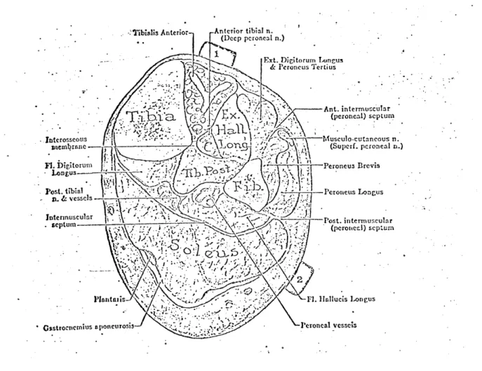
Based on the above evidence, a decision was made to perform the measurement of the stretch reflex at a different joint with a more defined muscle pair
(agonist-antagonist) and with the capability to accept torque without dis-comfort or pain. The ankle joint ad the major muscles associated with it, the gastrocnemius, the soleus and the tibialis anterior, were found to be
appropriate. The mode of plantarflexion and dorsiflexion of the foot was considered over the previous pronation/supination mode. (Note: Patients with fused ankle joints will not be tested.)
1.5 Objectives of this Thesis
The long term goal of this project is to develop a clinical device and method
which will assist the physician and physical therapist to objectively assess
spasticity. The device will be useful in the evaluation of the effectiveness of therapy, and will assist in the early detection and diagnosis of spasticity. This system should be simple to operate and the results reproducible and
easy to interpret. It should be as versatile as possible for use in the
investigation of spasticity in a variety of ways and must be acceptable by
12
The immediate objectives of this research are as follows:
1. Construction of the prototype experimental device.
2. Preliminary evaluation of the new design on a pool of normal and spastic subjects and suggestion of the proper refinements of the
device and test protocol.
3. Provide a guideline for the automatic data analysis procedure,
and derivation of the most suitable parameters for clinical assessment.
4. Installation of the equipment in the hospital for the actual evaluation of patients and correlation of the new objective
measures with conventional clinical evaluation.
It should be stressed here that the emphasis of this thesis is on the design and development of the clinical instrument, rather than on the
physiological investigation of spasticity and its mechanisms.
1.6 Outline of the Thesis
Chapter II describes the device which was developed for the measurement of
spasticity. It covers, in some detail, the different components of the apparatus, instrumentation used in gathering the data, safety precautions and the interface between the subjects and the system.
Chapter III deals with the computer control of the system and data acquisi-tion, display and analysis and gives a general description of the equipment
and programs used.
Chapter IV describes the experimental protocol and presents the results ob-tained from experiments with normal subjects. The effects of fast, slow and sinusoidal displacements, with different velocities and initial conditions
are presented and the physiological implications of these results are discussed. Chapter V presents some data obtained from two spastic patients and shows the
usefulness of objective assessment of spasticity.
Chapter VI summarizes this work and gives a few conclusions and recommendations
CHAPTER II
TWISTER - AN ELECTROMECHANICAL FOOT MANIPULATOR
2.1 Introduction
For the assessment of spasticity, it would be useful to have equipment with which it is possible to expose a muscle to a well defined dynamic and static stretching. Since the exact parameters influencing spasticity are not known
at present, the apparatus should be general and flexible enough to allow a variety of interactions with the neuromuscular system under investigation. Basically, the device should be capable of moving the tested limb in a similar manner as is presently done by the clinician. Since spasticity depends on the rate of stretch and amplitude of stretch, it is important that dynamic inter-actions be obtainable over a wide pertinent physiological range of velocity,
position and torque of the joint, in order to be able to extract the most
dominant parameters. As mentioned earlier, a variety of mechanical disturbances
introduced to the musculature were reported in the literature. Constant velo-city ramps, sudden steps in position, and sinusoidal functions are most common.
The majority of instruments were too cumbersome and complex to be used in the
clinic by a clinician. Thus, a system that would be able to accurately move
the patients foot about the ankle joint with capabilities including and
exceed-ing these features had to be constructed.
2.1.1 Design Criteria
To establish the necessary design criteria for the manipulator, parameters
of the mechanical limits of the human foot about the ankle joint were
ob-tained from the literature [Hansen, 1958; Kinkade, 1972]. The neutral
position for the ankle is with the lateral border of the foot at 90 with
the axis of the leg and in midposition as regards to inversion and eversion.
The average limit of plantarflexiion ofthe ankle is 350 from the neutral position with the average limit of dorsiflexion at 20* from the neutral
posi-tion. Thus, the average total travel angle of the foot about the ankle joint
is 55*. The actual physiological range of movement during level walking is
200 to -254. Other investigators [Herman, 1970; Kearney, 1976; Agarwal,
1977] have conducted their studies within smaller ranges: -30' to 100, ±14* and ±40 respectively. Thus, taking into consideration the variability in the data, a total maximum range of 600 was chosen.
The average, voluntary induced, maximum ankle torque varies between 520 in-lb (58.8 n-m) at 30* plantarflexion, and 1600 in-lb (181 n-m) at 200 dorsiflexion (subjects were aviation cadets). These are fairly high values as expected, since the triceps surae are among the strongest of the human muscles. However,
somewhat lower torque levels would be expected during the use of Twister since the patients would not voluntarily introduce maximal forces. As reported in
related work, maximums of about 700 in-lb (79.2 n-m) were recorded in moderately
severe spastic patients. Most normals and spastic patients did not exceed
200 to 240 in-lb (27 n-m). Therefore, to be conservative, a maximum anticipated
torque of 1000 in-lb (113 n-m) was assumed. With respect to the maximum velocities required, it has been reported that velocities up to 150'/s were
14
generally used to test spastic patients [Herman, 1970; Bomze, 1973].
The bulk of the experiments were conducted at speeds between 300/sec and 100*/sec for ramp function inputs and up to 0.9 Hz for sinsoidal. The physiological range frequency response of theiankle joint for both voluntary oscillations and level walking shows a corner frequency of about 6.0 to 6.5
Hz [Agarwal, 1977]. It would be reasonable to assume that patients would have
to be tested at lower frequencies than 6.0 Hz since their muscles' sensitivity to velocity is higher than in most normals. Thus, slewing rate of the
loaded system should be about 400*/sec.
In addition to these basic design criteria, the system should have the
following features. Simplicity - to avoid complicated manufacturing
prob-lems, since most of the components (mechanical and electronic) had to be "do it yourself". Easy to operate in the clinical environment without inti-midating the willing clinician. Accurate enough to provide repeatable
stimulus and data. Aesthetic and compact - to be accepted by both the
patient and clinician, blending into the clinical environment. Rugged and
moveable so that it may be wheeled around the clinic easily and safely. It
must meet not only the hospital safety standards and regulations, but must be acceptable as safe by the patient and clinician alike.
Based on the above preliminary criteria, two different systems were
con-sidered: hydraulic and electrical. An hydraulic system would have been the best solution in terms of dynamic perfomrance and torque, but it was ruled out for several resons: (a) cost - it is about three times as expensive as an electrical system; (b) it would be cumbersome and bulky, especially the power unit (pump, accumulator, actuator, valves, hydraulic lines, etc.);
(c) noise, from the pump and valves; (d) messy - requires constant maintenance, oil leaks; (e) not easily transferable - disconnecting hydraulic lines, etc. An electromechanical position servo system was chosen as the main drive of the foot manipulator, since it is less expensive, less cumbersome, compact,
quieter and easy to handle and maintain.
2.1.2 General Description
Figure 2.1 is a photograph of "Twister", the foot manipulator. The patient
sits on ethe dental chair (in a comfortable position), his foot strapped to the adjustable pedal. The pedal is connected on one side to the drive shaft and
on the other side to an idle shaft, which in turn is connected to a position potentiometer. A strain gauge bridge is mounted on the drive shift to monitor the torque. The shaft is driven by a quadrant pulley, cable driven by a
permanent magnet DC torque motor. Enclosed in the instrument box are the servo control, safety logic unit and a rechargeable battery. The system
is fixed to an adjustable plate, allowing an angle to be set from 0* to 90*
relative to the supporting cart. The power unit is placed in the large box
contained within the cart's frame. The entire system is mounted on rollers and can be moved about.
Figure 2.1: General view of "Twister", the foot manipulator -44
INI
Figure 2.2a:Close-up of the pedal
showing a subject's foot strapped in place
-4-
'K---r ---, 4-2.2 Mechanical Structures
2.2.1 Supporting Frame
The supporting frame can be divided into two structures: the upper structure consists of a large base, a flange-mount for the torque motor and two bearing
supports to accommodate the shafts with the pedal. The entire structure
can pivot to allow adjustments in the position of the leg and the foot (for testing at any position between 900 flexed leg about the knee joint to
fully extended leg). All parts are made of aluminum alloy, pinned and bolted so that they may be taken apart and put back together without
dis-turbing the alignment. The cart is made out of "Dexion", modular perforated
L-strips, bolted together, and carries the upper structure and the power supply unit, on wheels. There are two perforated angles extending from underneath the cart to allow adjustments of the distance between the dental chair and
the pedal. It also provides a closed-frame structure between the cart and the
chair that takes up the reaction forces and prevents relative motion. (See
drawings in Appendix A.)
2.2.2 The Pedal Assembly
Special attention was given to the design of the pedal. It is strong, yet lightweight for low inertia. It accommodates different size feet and holds them in place with minimum relative motion between the foot and the pedal. It is adjustable in both vertical and horizontal directions to enable proper
adjustment and alignment of rotation. This is only an approximation since
there is no one dimensional perfect axis for the ankle joint [Isman and
Inman, 1969]. Of great importance is the maintenance of heel contact through-out the experiment, since plantarflexion of the foot tends to raise the heel. The restraining device for the foot is quick and easy to apply and covers a wide range of different size adult subjects, male and female, with minimal
discomfort or pain.
The pedal assembly consists of two segments, the pedal and the foot fixation
elements. The pedal is made of perforated aluminum sheath 1/16" thick, bent and reinforced for strength. It rides within a U shaped aluminum frame via
elongated slots which permit 2.5" of vertical travel. The pedal length can
accommodate up to size 11 feet.
The usual methods to fixate a limb reported by several investigators is to
use a molded cast, individually fitted to each subject. This method is very
time consuming, requires some degree of expertise, accommodates only one particualr subject and does not allow for variations in the size of the limb
due to swelling of body tissues. Others use velcro straps or inflatable
cuffs which do not eliminate all relative movement.
Thus, a different type of foot holder was designed. Figure 2.2 shows the foot holder. It consists of a symmetrically moulded heel cup that fits
(with or without wedges) over the calcaneum at a level under the malleolus.
This holds the heel down firmly and comfortably. To "lock" in place the talus, navicular, cuboild and the three cuneiform bones, two nylon crossed straps with velcro are used. A piece of sheepskin is used under the strap
for cushioning. Holding down the rest of the foot (the metatarsals and pha-langes) is a 2" wide velcro strap.
/
11
iiI
.1~ Figure 2.3:A view of the drive train,
cable tensioning device, mechanical stops, cam
assembly with limit switches and torque
transducer
-~
N-V
04
Figure 2.2b
- Close-up of the pedal
- showing heel cup and
foot rest
tob
IS d~11
-, w-
/ -/ - - --18
The heel cup has a flat extension to which two screws are attached. This allows the unit to slide on top of the pedal forward and backward
in li long slots for horizontal adjustment of the ankle center of
rotation. Tests have shown that the foot can be strapped in the pedal
for about an hour without the subject feeling any discomfort, pain or
edema.
2.2.3 The Drive Train
Since the motor's maximum torque was less than the maximum anticipated, the motor could not be directly coupled to the foot manipulator drive shaft. A 1:7 torque amplification was required. At first a gear system was considered, including worm gears, however, it was ruled out for
several reasons: (a) susceptible to backlash, (b) large in size and weight (for the torques transmitted), (c) requires good alignment
(accurate machining), (d) introduces increased torsional elasticity in the system, and (e) requires lubrication to reduce friction and wear. A second consideration was gear belts and pulleys. Although it is slightly better than the gears, the size and weight of the components is very large due to the transmitted torque and velocity required, that effects the size of the belt and its allowable radius of curvature. Therefore, a third solUtion was adopted: a cable pulley combination. Since the foot motion is limited to 600 total range, a section pulley
is sufficient.
Figure 2.3 shows the pulleys that were designed to yield practically
backlash free motion. It consists of two, pretensioned, stainless steel aircraft cables, 1/6" in diameter, stretched around the surface of two
pulleys. The system allows slight misalignment in both the vertical and horizontal planes and is small insize with: a high torque to inertia ratio. The torque is transmitted from the motor via the cable pulleys through a semihollow stainless steel shaft (which also serves as the torque
trans-ducer) to the pedal assembly. Adjustments of the tension of the cables can be made via the cable tensioning bolts (see Appendix A).
2.3 The Electromechanical Position servo Mechanism
2.3.1 General Description
The electromechanical position servo mechanism is shown schematically in Figure 2.4. The position command is compared with the feedback from the position potentiometer and tachometer, the error is amplified by the linear power amplifier which drives the DC torque motor to the desired
position. To reduce the sensitivity of the system to disturbances and
parameter variations, and to have wide system bandwidth, a high gain in the open loop transfer function is desired. Such a system will appear
as a "stiff" system that can follow a position command despite disturbing
torques. Consequently, as the gain is increased, the system tends to become unstable. To overcome this difficulty, a tachometer feedback is
used in addition to the position potentiometer. The electronic part of the system is hard wired on vector board placed in a 5" x 5" c 4 1/4"
EXTERNAL LOAD - - (FOOT)., LIMITTER SU=MATION LINEAR D.C. PEDAL
andTAL PORER TORQUE and
AMPLIFIER MOTOR GEAR 7:1
BUFFER TACHOMETER
BUFFER
POTENTIO-METER
Figure 2.4: Block diagram of the electromechanical position servomechanism
Figure 2.5a:
Front panel of the hard-wired control circuitry box 4,,
All
-- -- ! Off -nk- -Po n ch.hqu
u.-VL -~J!l 'C
A
,
~. -I POSITION COyXAtNDi
. 1-12 0
sloped BUD instrument cabinet (along with other circuits) shown in Figure 2.5.
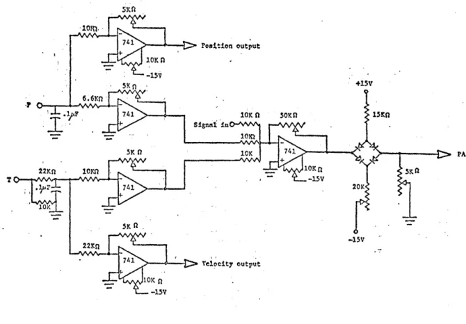
2.3.2 Motor and Power Amplifier
The foot manipulator is driven by a direct current permanent magnet servo motor (Magnetic Technology P/N H5500-750-040) capable of producing 14 ft lbs peak torque and no load speed of 55 rad/sec (see Appendix A). With
the 1:7 gear ratio, the required torque and velocity can be achieved. It
was determined that the power required to drive the system is about 400
watts. To meet this power demand, a 525 watt linear power amplifier was
chosen (Torque Systems, Inc. Model PA-601), along with a matching power
supply unit (Torque Systems, Inc., Model DPS-40-25. Figure 2.6 shows the hookup configuration of the amplifier.
Note 1: Both sides of the motor shaft were modified. On the output shaft, a flat surface was machined to secure the driving pulley onto the shaft. the rear end ofthe shaft was machined to accommodate the added tachometer.
Note 2: A pulse width modulated power supply was considered at first, but
it produced excessive audible noise with changing pitch when the motor was
running. This was a disturbing factor, particularly in the context of measurement of spasticity, which is known to be affected by ambient
con-ditions, such -as auditory noise.
2.3.3 Feedback Circuitry
The feedback circuitry (Figure 2.7) consists of three stages. The first
stage is a set of pre-amplifiers that allow individual adjustments of the position feedback open loop gain and velocity feedback loop gain. The
adjusted feedback signals are summed up with the command signal in the
second stage. In addition to the summation at this
junction,
there is an adjustable gain and bias. The output of this stage is the is the error signal which goes through a simple diode bridge limiter that can be adjustedto limit the maximum velocity of the pedal. (Note: This is optional. At
present, with the existing power amplifier, this limiter is not being used.) The circuit is built on a 1 1/2" x 2" vector board. The velocity
trans-ducer is a permanent magnet DC tachometer (Servo-Tek SA7247A-2, Size 11) with a sensitivity of 7V/1000 rpm (0.67V/rad/sec). The tachometer is
coupled to the motor shaft via a bellows coupling to allow slight misalign-ments between the tach shaft and the motor shaft. (The position transducer
is discussed later in this chapter.
2.4 Electromechanical Transducers
The kinesiological parameters of interest for possible assessment of spas-ticity are required as output information from the system. The parameters
of interest in this study are (1) the angular position of the foot (and its first derivative, i.e. angular velocity); (2) the resistance encountered during the stretch of the muscle, i.e. the torque produced at the ankle
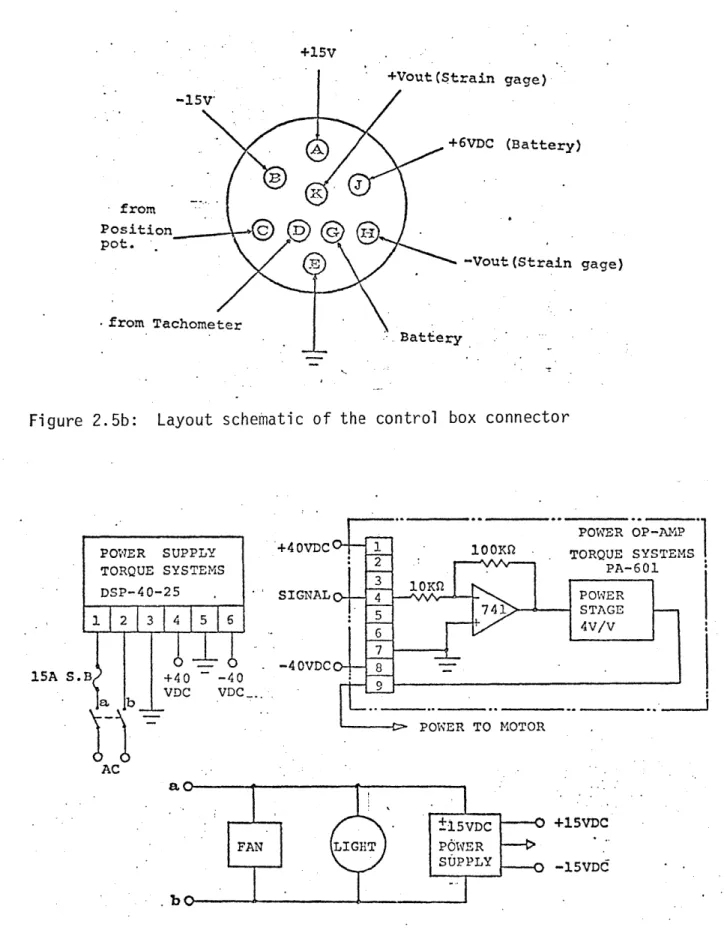
+15V +Vout(Strain gage) 157 +6VDC (Battery) from Position C D
-Vout (Strain gage)
from Tachometer
Bat-Eery
Figure 2.5b: Layout schematic of the control box connector
POWER OP -AMP
POWER SUPPLY +4OVDC 1 100K . TORQUE SYSTEMS
TORQUE SYSTEMS 2 PA-601
DSP-40-25 - IAPE 3 ~~ 741 STAGE 1 2 13 1456 - -4VDC 8 15A S.B +40 -40 VDC VDC ab POWER TO MOTOR AC FAN ±15VDC +15VDC LIGHT POWER SUPPLY -15VDd . bo
Figure 2.6: Linear power amplifier and associated components; schematic circuitry
.~'. L 741. Poattion output 10K n -15* SK n -+15V 6.6m, -P A - 1 741 10K n 5OKn I5n 7 -552V 100 f G Jn 10Kn BURR-BR W n - H
7 8 STRAIN GAGE BRIDGE
BIAH #FAED-12-35-SG
-15V 15
OUTPUT
ducers and circuits used to measure these variables are described in the
following sections.
2.4.1 Measurement of Angular Position
For the position feedback and measurement of angular position, an infinite resolution plastic film potentiometer is used (Bourns Model 6674, Custom
Precision) with resistance of 5 Kohms and linearity of 0.25% of full
schale. Voltages of ±15 volts, symmetric to ground, were applied to either end of the resistive elements so that a full turn produced a 30 V change on the slider. The 5K ohm was chosen to compromise between the amount of current drawn from the power supply and the undesirable variation
of output impedance with position. The potentiometer has an actual mechanical travel of 3000 ± 5. Since it is directly coupled to the idle shaft of the peda] via a bellows coupling, its travel is limited to a maximum of ± 300. In order to minimize non-linearities, the potentiometer signal is fed through a high input impedance buffer. The gain between the potentiometer output
to the computer and the angular postiion of the pedal was measured as 0.0235 V/degree. Total travel will, thus, produce ± 0.705 volts at the computer A/D input. This is desirable since the maximum input to the
present computer is ± 1 volt.
2.4.2 Measurement of Torque
To measure the torque produced between the motor and the foot pedal, a strain gauge bridge torque transducer was designed. The transducer
con-sists of a hollow round stainless steel shaft, two pairs of 450 rosettes, a voltage supply, and a high gain CMR amplifier.
The two rosettes (BLH Model FAED-12-35-SG) are affixed to the shaft with
clear cement (BLH #EPY-150). They are placed in diametrically opposing
potentions on the shaft with high precision. This symmetrical configuration
virtually nulls all effects of bending strain, tensile or compressive, and
measures only pure torque. Temperature effects are also eliminated by this configuration as well as other sources of electrical noise. Sensitivity of the torque transducer is a function of the strain in the shaft section. It is given by
= M r /TG(r - r ) (2.1)
where M is the torque moment, G is the shear modulus and r0 and r. are the outer aid inner radii of the shaft. The gauge voltage is
e = VBAR/R (2.2)
where R is the resistance of each strain gauge, V is the battery voltage
applied across the bridge and AR is the change iA resistance when the gauge is stressed.
(2.3) AR/R = GFe 45*0
24
where GF is the gauge factor. Thus, since there are four gauges, the total transducer voltage output is
VT 4 VB GFs450 (2.4)
With the particular shaft diameters, a given GF of 2.1 and an excitation voltage of 6.34 V, the transducer output is 6.71 x 10⁻⁶ volts/in-lb.
This requires amplification of about 750 to achieve about 0.005 volts/in-lb. For this, a Burr-Brown low drift instrumentation amplifier (3662 JP) with
high CMR has been used. Figure 2.8 shows the schematic diagram of the
amplifier and strain gauges. (See Appendix A for the transducer shaft dimensions.)
The excitation voltage of 6.34 V is supplied to the strain gauge bridge by a rechargeable battery (GEL/CELL #GC 610-lB). The battery is placed inside the BUD instrument box and can be periodically charged by a battery.charger
(GEL/CELL #GRC-6150-CDE) via the "battery charge" socket. Usually the limit
on bridge current is 30 mA. Since the gauge resistance is 350 ohms, 6.34 volts is a reasonable value for the bridge voltage (yields 18 mA). It is
very important to keep the battery charged on a regular basis, in particular
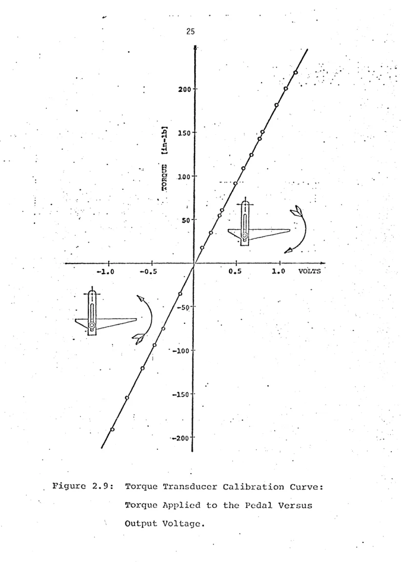
before experimental runs. The calibration curve for the torque is shown in Figure 2.9. The torques measured were symmetrical in loading-unloading and highly linear. A linear equation which relates the torque T to bridge
output V, is:
T = 193.75(V - 0.039) in-lb (2.5)
Accuracy is within 1% of full range. The torque measured by the
trans-ducer is comprised of a significant inertial component in addition to the
torque is given by
TGAUGE = TANKLE + (iFOOT + JPEDALXX (2.6)
where TGAUGE = output of the torque transducer
TANKLE = torque produced by the ankle, i.e. viscous damping, stiffness, reflex and voluntary contractions. JFOOT + JPEDAL = moments of inertia of the foot and pedal,
a = angular acceleration
Usually, the inertial components are subtracted from the transducer's output. This is done by oscillating the subject's foot passively while the subject
is completely relaxed, and measuring the angular acceleration and torque. However, in this apparatus, there are no provisions to measure accelerations nor to compensate for inertial loading. The inability of the patient to
relax and the aeneral characteristics of spasticity as mentioned in Chapter 1 make it impractical to measure the inertia of the foot. As a result, a brief transient, in the early portion of the torque response to fast
9-' en 9-4 I 1g4 b.d 0 I-' 200- 150- -100-501 --1.0 -0.5 -50 --200 0.5 1.0 VOLTS
Figure 2.9: Torque Transducer Calibration Curve:
Torque Applied to the Pedal Versus
26
2.4.3 MES Recording
Assessment of the electrical activity of the muscle can be done through the measurement of the Myoelectrical signals (MES) produced during muscular
contraction. Measurement of the MES is valuable for determining the levels
of muscular activity during the experiment, the timing of these activities and the relationship of these parameters between the agonist and antogonist muscles. In particular, the MES records can reveal the different components of the muscle response to stretch, such as the onset of the stretch reflex and the timing of a voluntary response.
The MES can be measured either by intramuscular electrodes or surface
electrodes. Intramuscular electrodes were not considered because of the complexity and risks involved in their use. These electrodes are invasive
and cause pain, tissue damage, infections and require trained personnel to
administer them. They also detect activity of a rather small number of
muscle fibers which do not represent the overall activity of the muscle
as a whole. Surface electrodes were selected for they are simple to apply, give good representation of overall muscle activity, are non-invasive and
are readily accepted by the subjects. They cause pratically no discomfort and are safe to use.
The MES surface electrodes used are Jacobson [1973] PDP-3 (Project and
De-sign Laboratory, University of Utah) (currently sold by MCI - Motion Control
Inc.). They consist of an at-the-site differential preamplifier with unique
features: No conductive electrode jelly is needed due to the high input impedance (10"Q), high common mode rejection ration (CMRR % 91db at 500 Hz) and low input bias current (25 picoamps), and insensitive to ambient electrical
and mechanical disturbances. The two electrodes are physically connected and maintain constant relative distance from each other.
The small size of the preamplifier allows it to be placed on the skin directly
above the muscle being monitored. It has a gain of about 310 and a bandwidth of 5 Hz to 17,000 Hz. The preamplifier is battery powered (Mallory Duracell #TR286, 12.6 volts) with 6.8 volts supply. This avoids the hazards associated with AC power and provides good electrical safety.
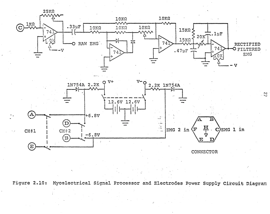
The raw MES is full wave rectified and then low pass filtered with a second order Butterworth filter which reduces the signal by 3 db at around 90 Hz.
This provides a short time constant and allows fast changes in the envelope
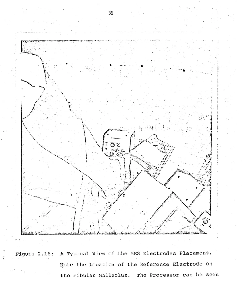
to be followed without introducing much phase shift. Figure 2.16 shows the
MES processor and electrodes and Figure 2.10 shows the schematic diagram of
the processor electronics. Note: The batteries of the EMG processor should
be regularly checked for proper voltage otherwise performance might be impaired. 2.5 Safety Mechanisms
Twister is capable of applying forceful movements to the foot about the ankle joint. A whole hierarchy of automatic and manual limiters has been provided to ensure stringent safety precautions. Special measures have been taken to protect the subject from exceeding his maximum comfort range of travel (i.e.
10KQ 1 OKS
C -- 33F 0 10K 10KQ
7 41 - 15KS .4F
S20K
-0 RAW EMG- 74 RECTIFIED
-V74 + .47p1F 741 ~FILTERED ~ OK EMG - -V V+ V 1N754A 2.2K 2.2K 1N754A 'r7 12.6V 12.6V +6.8V CH 2 EMG 2 in -6.8V F C EMG 1 CONNECTOR
Figure 2.10: Myoelectrical Signal -E 1
CH1
in
28
The cable-pulling arrangement does not allow movements beyond 33 degrees either in plantarflexion or, dorsiflexion. Any movement exceeding this
limit would cause the cable to release from the tensioning device and the
pedal will be physically disengaged from the motor. This is a very extreme
situation. Usually, the pedal will stop, if anything else fails, via the large pulley section, against the mechanical stops (set for + 30 degrees). This range can be adjusted to about + 15 degrees by the two adjustment screws
mounted on the mechanical stops' arms. Before the mechanical stop is reached,
a switch will be triggered by an adjustable cam assembly (pick IPL-3), which
will cut off the power to the motor. Currently, this trigger is set to operate at + 29 degrees.
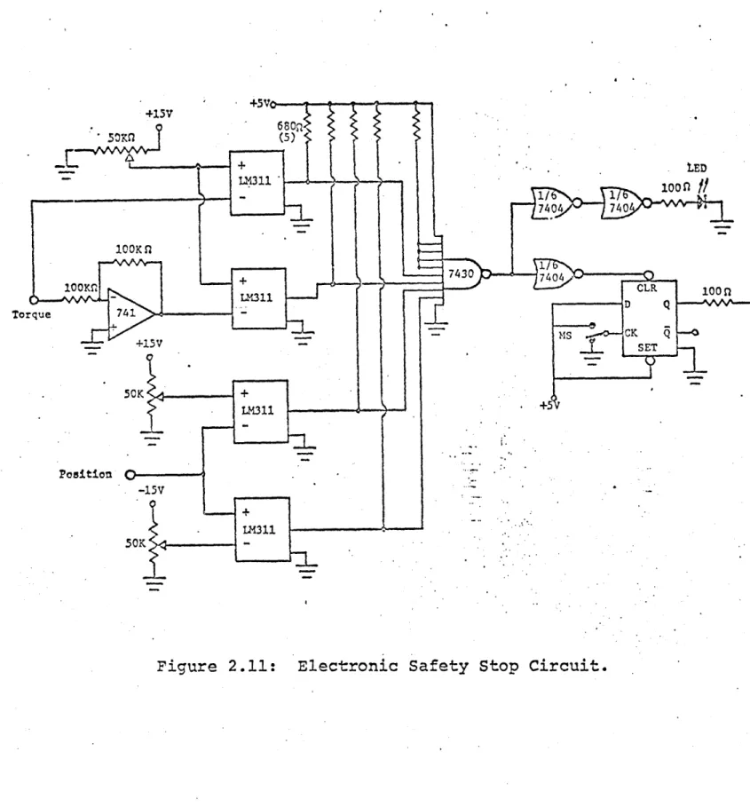
Ideally, these three safety levels would never be tripped. Generally, the electronic stop safety mechanism would ta.ke care of stopping the device in
cases where the subject's limits are exceeded. A schematic of the electronic stop circuit is shown in Figure 2.11.
Two potentiometers allow the subject's upper and lower position limits to
be set. The position of the pedal is compared by the voltage comparators
(LM 311) to the preset limits. As long as the pedal is within the limits,
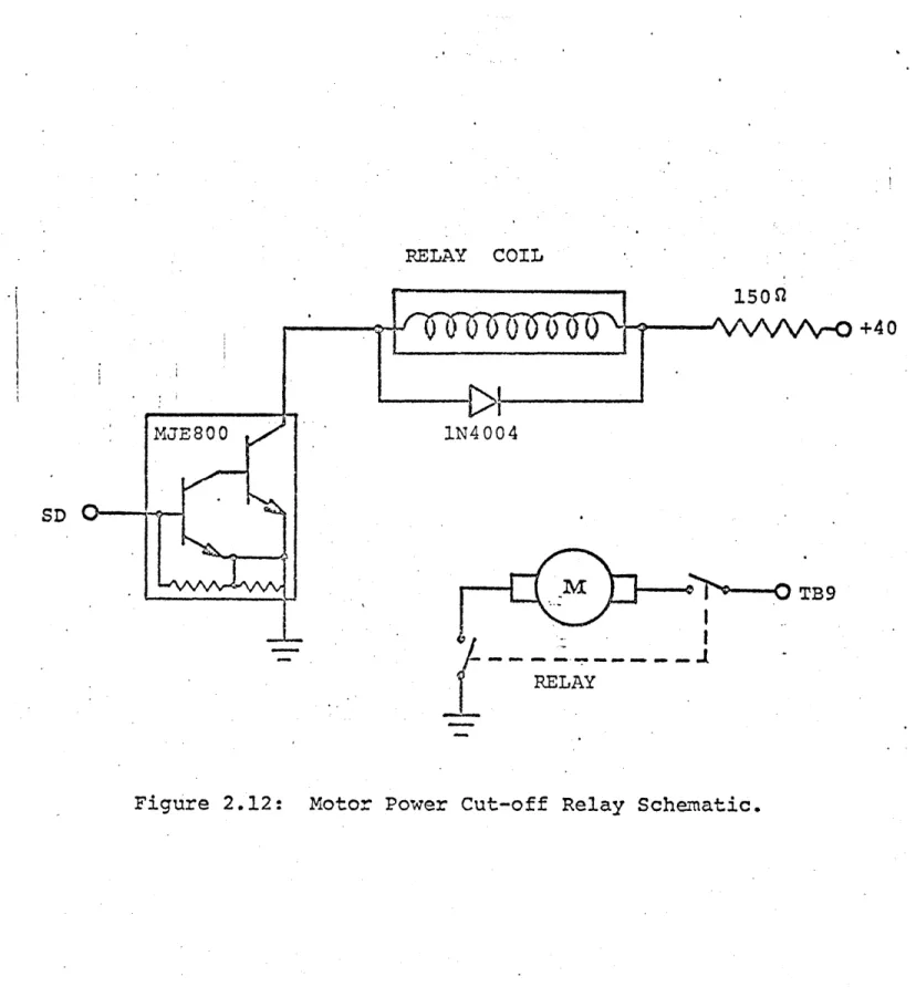
the safety relay coil (Figure 2.12) is energized and power is supplied to
the motor. Once the pedal exceeds one of the limits, the logical "OR" gate output goes to logical "HIGH" causing the set-reset flip-flop to reset which
is indicated by the activated light emitting diode. Subsequently, the relay is deenergized and the power to the motor is shut-off. Once tripped, the system remains inoperable until a reset button is depressed. (The action is done manually and the operator must make sure that the pedal is at ap-proximately its bias position, otherwise the pedal will move abruptly to
that position.)
In addition to these position limits, a torque limiter is provided and can
be set via the torque limiter knob. The torque should be set usually by
asking the subject to push on the pedal at maximal force and adjusting the
system to trigger at that level. Usually it is enough to set the system at about 250 to 300 in-lb. The torque limiter works in the same manner as the
position limits.
Another safety feature is a manual "discomfort button" readily accessible by the subject which disables the system when triggered. This switch is mounted on the subject chair's arm and accidental triggering when the pedal is not in motion or loaded at a certain level, will not disable the system. In addition to the above mechanical and electronic safety "hardware", safety
provisions are included in the computer control "software". Subroutine
"LIMITS" (see Appendix C) does not allow the program to continue unless the
subject's lower and upper position limits are actually set. These limits are sampled by the computer and stored in memory. Then, the computer will
not accept any keyboard commands that require positions outside the preset
limits.
Usually, the initial position of the pedal at the beginning of the protocol
+ LED *-LR311 100 n -77404 740 500K n 7430. 100MLM1 CLR 100 n Torq e374 D Q --- N - - SD oque
I4
~M- CK Q --. +15V SET . 5K + LM311 .+5 Position -150 -LM311?ELAY COIL +40 VDC MJE800 1N4004 SD --TB9 RELAY