Developments and Applications of THz Polaritonics,
Efficient THz Generation, and Single-Shot THz Detection
by
Benjamin Kwasi Ofori-Okai
B.S., Yale University (2009)
S.M., Massachusetts Institute of Technology (2013)
Submitted to the Department of Chemistry
in partial fulfillment of the requirements for the degree of
Doctor of Philosophy
at the
MASSACHUSETTS INSTITUTE OF TECHNOLOGY
June 2016
MASSACHUSETTS INSTITUTE OF TECHNOLOGYJUN 232016
LIBRARIES
ARCHNES
@ Massachusetts Institute of Technology 2016. All rights reserved.
A uthor ...
Certified by...
Accepted by ...
Signature redacted
D eartment of Chemistry
May 18, 2016
Signature redacted
Keith A. Nelson
Haslam and Dewey Professor of Chemistry
Thesis Supervisor
Signature redacted
Robert W. Field
Chairman, Department Committee on Graduate Theses
This doctoral thesis has been examined by a Committee of the Department of
Chemistry as follows:
Professor Moungi G. Bawendi...
Signature redacted
U
Chairman, Thesis Committee
Lester Wolfe Professor of Chemistry
Signature redacted
Professor K eith A . Nelson ...
...---...---Thesis Supervisor
Haslam and Dewey Professor of Chemistry
Professor Robert W. Field ...
Signature redacted
Member, Thesis Committee
Haslam and Dewey Professor of Chemistry
Developments and Applications of THz Polaritonics, Efficient THz
Generation, and Single-Shot THz Detection
by
Benjamin Kwasi Ofori-Okai
Submitted to the Department of Chemistry on May 18, 2016, in partial fulfillment of the
requirements for the degree of Doctor of Philosophy
Abstract
In this thesis, I describe work aimed at improving the two primary terahertz platforms that are used within the Nelson group: terahertz polaritonics and free space high field terahertz spectroscopy. The terahertz polaritonics platform consists of a thin slab of electro-optic material in which terahertz frequency radiation is generated, manipulated, and detected. The platform is unique in that the teraherz fields can be recorded using phase-sensitive imaging technique to observe the full spatiotemporal evolution of the field. In the free space regime, the terahertz field propagates in free space between a transmitter and a receiver. By using appropriate crystals and focusing optics, it is possible to achieve high field strengths capable of driving nonlinear responses in materials.
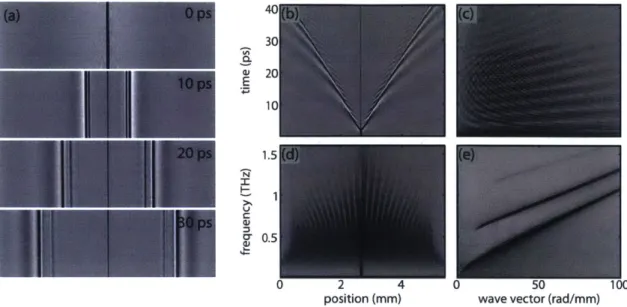
The first project presented describes improvements to the two imaging techniques used: phase contrast and polarization gating. By using improved optical designs and detection hardware, we obtained a best image resolution of 1.5 rm (< A/100 at 0.5 THz) using po-larization gating, and a noise floor of 0.1% for popo-larization gating. Using the low noise floor of polarization gating imaging, we demonstrate for the first time the ability to per-form time resolved imaging of terahertz waves propagating within a photonic crystal slab. For photonic lattices with different orientations and symmetries, we observed the full spa-tiotemporal evolution of terahertz fields across a broad spectral range spanning the photonic band gap. In addition to revealing real-space behavior, the data let us directly map the band diagrams of the photonic crystals and observe the behavior of leaky waves and the individual components of the photonic crystal Bloch states.
The next set of projects uses the free space geometry. We first present a novel method for THz generation in lithium niobate using a reflective stair-step echelon structure. The echelon produces a discretely tilted pulse front with less angular dispersion compared to a high groove-density grating. We produced THz pulses with field strengths as high as 500 kV/cm and pulse energies as high as 3.1 J. The highest conversion efficiency we obtained was 0.33%. Following this we discuss a method for single-shot detection of terahertz pulses using a pair of transmissive echelons. Finally, efficient THz generation and single-shot de-tection were combined to probe the effects of optical excitation in three solid state systems. The first was the semiconductor tin (II) sulfide, where optical pump terahertz probe spec-troscopy was used to determine optimal conditions for sample growth to improve solar cell devices. These measurements revealed that by annealing and surface treatment, the carrier lifetime of tin sulfide can be extended, thereby improving device performance. The next was the metal-halide chain platinum iodide where optical pump-terahertz probe spectroscopy
was used carrier self trapping. The results obtained here indicate that following photoexci-tation liberated carriers are trapped on the 100s of femtosecond timescale. Lastly, optical pump single-shot terahertz probe measurements were used to study the dynamics of a pho-toinduced insulator-to-metal phase transition in the correlated electron material calcium doped lanthanum manganite. The data indicate that on the 1 picosecond to 1 nanosecond timescale there is limited change in the conductivity of the material, suggesting that large scale domain growth is required in order for the material to reach the final metallic state.
Thesis Supervisor: Keith A. Nelson
Acknowledgments
At one point in my life, I believed that I wanted to get 5 PhDs. That's right. 5. At the time I was young, foolish, and did not have any appreciation for how difficult getting just one PhD would be. I also had not anticipated the incredible support that I would receive on this path. While the 5 PhD dream may never become a reality, the friends that I've made are the best I could have asked for. Without any of them, making it through graduate school wouldn't have been possible.
The first person that I need to thank is my advisor, Prof. Keith Nelson. At the end of my second year of graduate school when I was unsure of what would happen with my former advisor leaving, Keith kindly offered to take me in, and this has made all the difference. His dedication to his students, his enthusiasm for science, and his ability to constantly generate new and interesting ideas are all traits that I have tried to take on and use to grow at a scientist and as a person. His constant willingness to discuss any aspect of my work made me feel like no matter what I was struggling to understand, big or small, it was worth understanding and that I was never at fault for not getting it the first time. He always made it seem like any nearly impossible task could be accomplished easily, and that the world would be a better place for it. In addition, I have to thank the other members of my committee, Profs. Moungi Bawendi and Bob Field. Moungi not only deserves credit as the only member of my committee to remain unchanged during my time at MIT, but also for his help during my annual meeting by providing a different perspective on my work and new ideas and strategies for tackling problems. Bob was one of the first professors I interacted with when I visited MIT as an undergraduate, and he made me feel welcome from the beginning. I cannot say that I would be here had it not been for that meeting, but I'm glad that it is something that I did.
Next, I have to thank the students who taught me everything I know and were great role models for what I hoped to become. At the top of this list is Kit Werley, who was the graduate student who took me in and started to teach me from the beginning. Kit is the most patient teacher I have ever known and that is something I have tried to emulate as
I progressed through graduate school. Next is Johanna Wolfson, the senior student on the
single-shot project. Seeing how she worked through her experiments either on her own or with Kit gave me an appreciation for how varied science can be and how there is never one right answer to a problem. On the other side was Harold Hwang, the student leading team "Big THz". In the lab, he never seemed to get tired of all the things that needed to be done, and in the office he was always willing and interested in discussing not only his results but anything anyone else was working on. I can't thank any of them enough not only for their teaching, but also for being amazing leaders in the lab and great examples to follow.
Of course, the journey through the Nelson group school wouldn't have been possible
without my "classmates". The first of these that I need to mention is Prasahnt Sivarajah, who joined the group at the same time I did. Prasahnt is one of the hardest working people I know, and always keeps me on my toes. I am grateful for the time spent in lab collaborating on projects, and the introduction to Dragonball Z Abridged. Yongbao Sun and Jeff Eliason also contributed greatly to fun times in the group. Though I never worked with either, both were always willing to share knowledge, expertise, as well as discussing the latest and greatest feats of the NBA. There are also my thesis comrades, Colby Steiner and Sam Teitelbaum, who I have had the honor of sharing the thesis writing office with. "Wholesome" Colby is perhaps the most dedicated and loyal person in the group, as demonstrated by his tireless efforts to make sure that our labs remained in shape at all times during the insane
construction project, while also taking time to check in and see that we were all doing okay. And it has been a real treat to work with Sam, one of the most capable scientists I've ever met. I have been fortunate to not only share lab space with Sam, but also to work closely on the single-shot THz experiments on LCMO. Trying to keep up with him has made me a better scientist and was a task I greatly enjoyed.
The other students I got to know quickly were Patrick Wen, Dylan Arias, Raoul Correa, Nate Brandt, and Kara Manke. Patrick and Dylan made me immediately feel like I had been part of the group for years, even after it had only been days. I'll never forget the epic battles with Dylan in the hallway or on the PS3 (Boom Shaka-Laka!), and Patrick's late night charges into Chow-Chow City and The Hong Kong remain some of the best/worst nights of my life. Raoul, "The Enabler", Correa was the catalyst of many excellent outings to the Middlesex and the Enormous Room, but is perhaps most memorable to me for the night of Dylan's birthday that I will likely never completely remember, and maybe it's better that way. Nate and Kara started off as late-night office buddies, but quickly became constant sources of support and encouragement. I will always think fondly of the night Nate and I aligned optics while wearing suits. And Kara has become one of the closest friends and deepest confidants that I have ever had. I have enjoyed the many late night chats, walks, cat videos, and Star Trek viewing sessions with her, and cannot thank her enough for her constant willingness to listen.
In addition, I have to thank the other members of the Nelson lab that I overlapped with: Alex Maznev Sharly Fleischer, Brant Pein, Deniz Bozyigit, Jake Siegel have been great postdocs who brought new ideas and ways of thinking into the lab. While I never closely interacted with David Veysset, it was always great to see the progress he made in the
ISN. Jian Lu, Leora Cooper, Yoseob (Joseph) Yoon, Yaqing Zhang, Doug Shin, Yu-Hsiang
Cheng, Xian Li, and Wenqian (Ronny) Huang have been other junior students who I have had the opportunity to teach, interact with, and learn from. Finally, Ryan Duncan, Frank Gao, Jiaojian (Tristan) Shi, and Dmitro Martyonwych represent the future of the Nelson group, and I look forward to hearing about what they do next.
Finally, my actual classmates who have remained in close proximity during my time in grad school. Marco Jost was my ever dependable workout buddy, who helped me be-come stronger physically and mentally through many intense lifting sessions without ever sacrificing good fun drinking. Kevin Chang followed my former advisor to ETH, but I am thankful that we have stayed in contact. The original members of D.I.C. House central, Chris Lemon, Eric Victor, and Michael Funk, helped make returning home from lab, hur-ricanes, and snowstorms extremely enjoyable during the first three years of grad school. Chris in particular has been the most excellent roommate, enduring my completely erratic schedule, and engaging many late night discussions over science, beer, and the best TV on Netflix. Jennifer Scherer was the other member of chemgrad09 to live in the thesis writing office with me, and I am extremely grateful that we got to finish together. She was the original catalyst behind the thesis-writing movement (No Jenn/Ben left behind!), and made each day in the thesis writing office was like a Family Reunion. Her constant enthusiasm, curiosity, artistic prowess, and humility have been inspirational to me, and I'm proud to be graduating alongside her. Last, but by no means least, is Stephanie Teo. Steph was the first person that I met on day one of MIT, and for some reason she has stayed friends with me ever since. I don't know that I could have made it through switching labs, Fujimoto's optics, late-night (morning?) stints in the lab and learning to cook without Steph. I don't
know what else to say, except that I, too, am thankful that the universe knew better. For as much science as there was to do, none of it could have gotten done without those
-who focused on the not-science aspects of our lives. In particular, I have to thank Li Miao (she puts the "Li" in "Lifesaver"), without whom nothing would ever get done, as well as Susan Brighton and Jennifer Weismann who were constant forces for good and helped navigate the bureaucracy of MIT. In addition, my collaborators Prof. Steven Johnson and Chia Wei Hsu were helpful in discussions and simulations in chapter 4 and Mr. Koustoban Ravi for discussions of the echelon generation method. I had the pleasure of working with Prof. Longfang Ye when he visited the group and have enjoyed staying in contact with him afterwards, and Prof. Rafael Jaramillo and Prof. Sue Dexheimer provided great motivation and discussions for the experiments in chapter 7.
I have been lucky to know many MIT outsiders as well. Tina Ho and Cecilia Ong were fellow undergraduates who I have been fortunate to keep up with over the years. Frequent phone calls with Tina have always been a welcome distraction, and I look forward to many more. Ceci always has a way of showing up right when I need her most, and her time in Boston made my life richer and happier. Kathryn Chew, Jennifer Nguyen, Priyanka Lahiri, and Tina Thorson remained in New Haven after I left, but always made me feel welcome whenever I needed to flee Boston. I owe special thanks to Kathryn for always letting me crash on her couch, and never letting me forget that we were always in it together, even if we were struggling separately. Gillian Teo and Elizabeth Lemon constantly helped me keep perspective of life outside of science with TV and potential rice krispy treats ventures. Casi Newell has recently reappeared in my life, and I always enjoy her company. My former research advisor, Prof. Charlie Schmuttenmaer, as well as Prof. Patrick Vaccaro and Prof. Ann Valentine made me believe that I could make it through graduate school before it even began, and were always happy to hear about my progress. Alberto Medina, Grace Lu, Nicole Espy, Beth and Charlie Lesch, and Pam Wang eventually made their way to Boston and I have enjoyed watching them grow. The juggling cohort of Team YAGS, Sam Norman-Haignere, Katherine Rosenfeld, Phil Isola, and Valerie Larson, as well as our adopted non-juggler Katie Gordon have been great friends who were always willing to give me something to do when my mind got tired of optics. And then there are friends from the earliest parts of my life, Emily Arrighi and Andrew Strum, as well as Allana Schneidmuller and Samantha Wakefield, who always were there to remind me of who I was whenever I was in doubt.
Finally, there is my family who have been the best example of constant love and support that I have ever known. My stepmother, Sabina, and stepbrother, Kweku, have managed to make home always feel like home, even though I only visit once or twice a year. My dad was the first person I knew to have a PhD, has always encouraged me to do things that I never thought I could do, and has never been surprised if I managed to succeed. His "work hard and have fun" mantra have been essential, and I cannot thank him enough for that. And finally, my mom, who I've never stopped thinking about. She gave me everything that
I needed, whether I knew it or not, and I have always tried my best to do what would have
made her proud. There are no words that I can use to describe that - all I can do is hope that she knows.
To you, those included and those I may have missed, thank you. A million times, thank you.
Benjamin K. Ofori-Okai May 18, 2016
For Mom and Dad, who always believed in me, Me da ase.
And for my friends, who always built me up, Thank you.
Contents
1
Introduction 172 The Polaritonics Platform 27
2.1 Dispersion Relation of Phonon-Polaritons ... 28
2.2 THz Generation on the Polaritonics Platform . . . . 33
2.2.1 Optical Rectification and the Nonlinear Wave Equation . . . . 34
2.2.2 Solutions to the Nonlinear Wave Equation in LiNbO3 and LiTaO3 -Cherenkov Radiation . . . . 35
2.2.3 Experimental Details of THz Wave Generation . . . . 38
2.3 THz Detection by the Electro-Optic Effect . . . . 40
2.3.1 The Impermeability Tensor and Index Ellipsoid . . . . 42
2.3.2 The Electro-Optic Tensor . . . . 44
2.3.3 The Pockels Effect in LiNbO3 and LiTaO3 for Polaritonics . . . . 45
2.3.4 Phase Accumulation from the Induced Index Change . . . . 47
3 Polaritonics Measurements on the Slab Waveguide 49 3.1 Solutions to the Wave Equations in Anisotropic Planar Waveguides . . . . . 50
3.1.1 TE Modes of the Anisotropic Waveguide . . . . 54
3.1.2 TM Modes of the Anisotropic Waveguide . . . . 61
3.2 Improvements in Time-Resolved Phase-Sensitive Imaging Techniques on the Polaritonics Platform . . . . 65
3.2.1 General Experimental Details . . . . 66
3.2.2 Phase Contrast Imaging . . . . 67
3.2.3 Polarization Gating Imaging . . . . 72
3.2.5 Image Analysis Procedures . . . .
3.3 Conclusions . . . .
4 Wave Propagation in Photonic Crystal Slabs
4.1 Derivation and Properties of Maxwell's Wave Equation . . . . 4.2 Solutions to the Wave Equations in Periodic Systems . . . . 4.3 Experimental Study of THz PhC Slabs . . . . 4.3.1 R esults . . . .
4.3.2 Observing Backward Wave Dispersion in Photonic Crystals . . . 4.4 C onclusion . . . .
5 The Free Space THz Geometry
5.1 THz Generation via Optical Rectification . . . . 5.1.1 Mathematical Treatment of Collinear Generation . . . .
5.1.2 Limitations of Collinear Generation . . . . 5.1.3 High Power THz Generation Using Noncollinear Phase-Matching
5.2 THz Detection in the Free Space Geometry . . . .
5.2.1 Electro-Optic Sampling with Zincblende Crystals . . . .
5.2.2 Experimental Geometry and Data Acquisition . . . . 5.2.3 Time Resolved THz Spectroscopy with Differential Detection . . 5.2.4 Parameter Extraction . . . .
6 Developments in Free Space THz Generation and Detection 6.1 Echelon Based THz Generation . . . . 6.1.1 Echelon Design . . . . 6.1.2 Experimental Setup . . . .
6.1.3 THz Characterization Procedure . . . . 6.1.4 THz pulse energy and conversion efficiency . . . . 6.1.5 Discussion of Comparison . . . .
6.1.6 Conclusions and Future Experiments . . . .
6.2 Echelon Based Single-Shot THz Detection . . . .
6.2.1 Echelon Design . . . .
6.2.2 Trace Extraction Procedure . . . .
80 83 85 87 91 99 102 108 113 115 116 116 119 120 123 123 126 129 130 135 . . . . 136 . . . . 139 . . . . 141 . . . . 143 . . . . 145 . . . . 147 . . . . 149 . . . . 149 . . . . 150 . . . . 151
6.2.3
6.2.4
6.2.5
Hardware Considerations . . . . Timing Scheme . . . . Limitations and Further Improvements . . . .
153 154 156 7 Carrier Dynamics in Semiconductors and Metal-Halide Chains 159
7.1 Drude Model -Basic Description . . . . 160
7.1.1 Corrections Based on Quantum Mechanics ... 161
7.1.2 Application to THz-TDS and TRTS . . . . 164
7.2 Minority Carrier Lifetime Measurements on Tin Sulfide ... 165
7.2.1 Relevant Properties of SnS . . . . 166
7.2.2 Experimental Details . . . . 167
7.2.3 Modeling Considerations . . . . 168
7.2.4 R esults . . . . 172
7.2.5 Conclusions . . . . 174
7.3 Dynamics of Exciton Self-Trapping in Platinum Iodide . . . . 174
7.3.1 Optical and Electronic Properties of PtI . . . . 176
7.3.2 Experimental Details . . . . 177
7.3.3 Experimental Results . . . . 179
7.3.4 Conclusions . . . . 188
8 Time-Resolved Single-Shot THz Spectroscopy of a Photoinduced Phase Transition
8.1 Description of Relevant Manganite Physics . . . . 8.1.1 Structure Considerations - Crystal Field Splitting
D istortion . . . .
8.1.2 Tolerance Factor and Strain Engineering . . . .
8.1.3 Exchange Correlation . . . .
8.1.4 Description of Low Temperature Ground State . .
8.2 Experimental Considerations . . . . 8.2.1 Experimental Setup . . . . 8.2.2 Sample Details . . . . 8.3 R esults . . . . 8.3.1 Photoswitching Characteristics . . . . and Jahn-Teller 189 191 191 193 195 200 200 200 202 203 203
8.3.2 Single Shot Switching Dynam ics . . . . 208 8.3.3 Discussion . . . . 211 8.4 Conclusions . . . . 214
Chapter 1
Introduction
Over the past 30 years, there has been substantial growth in the field of terahertz (THz) science. Compared to other regions of the electromagnetic spectrum, the 0.1-10 THz range
(1 THz = 1012 Hz, 33 cm- 1 wavenumbers, A = 300 gm free space wavelength, 1 picosecond
cycle time, 4.1 meV energy, 48 K temperature) has been slow to develop due to a lack of bright sources of radiation or efficient detectors. The most significant development came with the use of the femtosecond (fs) laser system for generating ultrafast THz pulses [1, 2]. Since then, THz optics and THz spectroscopy have developed so significantly that THz fields can now be used to drive and probe nonlinear material responses [3-5]. Even with all of these advancements, and in some cases because of them, THz spectroscopy and technique development remain active areas of research within the scientific community.
The motivation for improving THz technology comes from the variety of applications that are available. In chemistry and physics in particular, THz spectroscopy is an appealing tool for studying material properties in condensed matter systems. Molecular resonances located at THz frequencies tend to be unique and can serve as markers for chemical iden-tification. There are also a variety of physical processes that occur on picosecond (ps) timescales, and THz fields can be used to measure the dynamics of these phenomena.
In this thesis, I will discuss my work using two specific tool sets for making THz mea-surements that have been used in the Nelson group: The THz polaritonics platform and the free space high field THz regime. Although these methods differ in the design details, they share common roots in nonlinear optics.
of ferroelectric crystal where THz generation, manipulation, and detection all take place [6]. Using ultrafast pulses, THz fields can be generated in either lithium niobate (LN, LiNbO3)
or lithium tantalate (LT, LiTaO3) through impulsive stimulated Raman scattering [7] and
be guided using a variety of photonic components either machined into [8-18] or deposited onto the slab surface [19-21]. However, the most interesting aspect of the polaritoncs platform is the detection scheme that takes advantage of the electro-optic properties of
LiNbO3 and LiTaO3 for recording images of the THz waves propagating and interacting
with integrated structures. Images of the THz fields can be recorded using time-resolved phase-sensitive imaging [22]. This allows for systems and photonic devices to be studied in the near field without the use of external probes. The imaging is carried out using femtosecond optical probe pulses, which allow the THz fields to be imaged with deeply subwavelength spatial and sub-cycle temporal resolution. Chapter 2 and the beginning of chapter 3 discuss some of the considerations and physics of THz polaritoncs. The specific details presented are represented in figure 1-1, with 1-1(a) and (b) illustrating the key points of THz generation and detection, respectively. Figure 1-1(c) shows an example of an image that can be collected using polaritonics. The light and dark areas correspond to positive
(a)
(b)
800 nmn
532 nmn
pump
THz
probe
(c)
Figure 1-1: The THz polaritonics geometry. (a) THz waves are generated within a thin slab of material by focusing an ultrafast fenitosecond laser pulse (red) through the material. The resulting THz fields (blue) propagate laterally away from the point of generation, remaining confined within the slab by total internal reflection. (b) THz waves are detected using an expanded probe beam (green) to image a large portion of the slab. (c) Images of polariton waves recorded using phase sensitive detection. The two counter propagating waves originated from the line in the middle where the pump pulse was focused into the slab.
and negative values of the THz electric field trapped within the slab.
The other experimental platform used in my thesis work was the free space THz regime. Figure 1-2 shows the basic layout of a simple free space THz experimental setup. Just as in polaritonics, interactions between an ultrafast laser pulse and nonlinear material are used to generate and detect THz radiation [23]. The difference lies in that the THz radiation is guided using conventional optics in free space, and is used to interrogate static material properties as well as dynamics of photoinitiated processes. By using appropriate techniques and materials, the THz fields generated can have large amplitudes (~
1
megavolt(MV)/cm) [24] which are capable of driving nonlinear responses in different materials. Both linear and nonlinear responses can be observed by either directly resolving the THz electric field in the time domain, or by measuring the change in the THz transmission through a sample following optical or THz excitation. In chapter 5, I discuss some of the capabilities that are available on the free space geometry, focusing primarily on THz generation and detection through the electro-optic effect.THz source
optical mechanical THz detection
chopper delay e ...
sample
80 n,15m emsplitter/
Figure 1-2: Free space THz setup. The source is an electro-optic crystal in which THz radiation is generated by optical rectification, a second-order nonlinear process. The THz waves are guided in free space using off axis parabolic reflectors to a sample of interest, and then to a second electro-optic crystal for detection. Using a mechanical stage, a second time delayed femtosecond pulse is used to read out the THz electric field.
Motivations and Scope
Technique DevelopmentThroughout this thesis, there have been two major goals which were the driving forces. The first was the desire to improve upon techniques that currently exist. In the polaritonics regime, my work has primarily focused on improving the imaging schemes that are used
for recording the images of polariton waves. The latter part of chapter 3 discusses my efforts in improving the spatial resolution and the signal-to-noise ratio of the two imaging techniques that are used in the lab. The first method I will discuss is phase contrast imaging which was optimized for observing near-field interactions between the THz field and other structures. As these effects are significantly subwavelength, a method with high spatial resolution is required. The system I developed has a resolution better than 1.5 jim
(< ATHz/100), and the minimum detectable signal was ~0.2 %. The second method, I will discuss is polarization gating imaging, a technique which records images with high signal-to-noise balanced imaging and is primarily used for measurements where the observed signals are small. Here, I made improvements which yielded a spatial resolution better than 5 jim, worse than phase contrast, but with a minimum detectable signal 0.1 %. Examples of the images that can now be obtained are shown in figure 1-3.
(a)(b
Figure 1-3: Images of THz waves imaged using (a) phase contrast and (b) polarization gating imaging. In both cases, the THz field interacts with metal micro-structures, a complex antenna in (a) and an array of split-ring resonators in (b).
In the free space geometry, both generation and detection remain active areas of re-search. My primary efforts on improving THz generation were focused on increasing the efficiency of THz generation in LiNbO3. Within the last 15 years, broadband nonlinear
THz spectroscopy has been enabled primarily by the use of LiNbO3 as a nonlinear material
for generation. The current technique which makes this possible requires a grating to in-troduce angular dispersion [25] in the pulse. This produces a continuously tilted intensity front [26,27] which can velocity match with the THz radiation in the LiNbO3 crystal. While
successful in producing THz radiation, the continuously tilted intensity front has adverse effects on the pump pulse, limiting the pump-to-THz conversion efficiency. This is especially bad when the pump pulse duration is less than 300 fs [28].
In an attempt to overcome this, I designed and had fabricated a reflective echelon structure. This reflective echelon can be thought of as a staircase with each individual step acting as a mirror that then splits a significantly larger beam into many smaller time-delayed beamlets. This effect is illustrated in figure 1-4(a) and results in a discretely tilted intensity front with considerably less angular dispersion than the continuous front produced by a typical grating. I demonstrated THz generation in LiNbO3 using the reflective echelon at
both room temperature and cryogenic temperatures. These results, discussed in the first half of chapter 6, indicated a pump-to-THz conversion efficiency of 0.33%, which is comparable to the highest reported value in the literature of 0.35% [29] when using laser pulses with comparable center wavelengths. While this value was slightly lower than the optimal case, it did exceed reported values which used pump pulse durations that were ~ 50 fs, where the generation cfficiency is usually <0.05%. In comparison, this work demonstrated a nearly 6-fold increase in the conversion efficiency.
(a) (b) THz pulse EO crystal Woll.
--'7:_~ tilted intensity
--
s--
frontoutput
hx20 Hx20QWP
- - dual
echelons
Figure 1-4: Echelon based THz generation and detection. (a) A reflective echelon is used to split a single input beam into many time-delayed beamlets producing a discretely tilted intensity front. This was used for THz generation in LiNbO3. (b) Transmissive echelons
used for single shot THz detection. In this case, the time-delayed beamlets are delivered to the electro-optic (EO) sampling crystal as a pulse train. The THz waveform is recovered
by imaging the echelons onto a camera with a quarter wave plate (QWP) and Wollaston
prism (Woll.) in the imaging path.
Typical spectroscopic THz measurements are performed in the pump-probe geometry. Readout of the THz field is accomplished by scanning a mechanical delay stage that delays the arrival of an optical readout pulse that overlaps with the THz field in the EO crystal, recording the THz field-induced depolarized readout pulse intensity of many probe pulses at each time delay. Many repetitions of the measurement are carried out at each of many time delays to characterize the THz field with a high signal-to-noise ratio. This method is sufficient for measuring either static properties or dynamics in reversible systems, but there
are process where the material does not return to its initial state quickly enough, if at all, before another measurement is made.
In order to try to surmount this problem, I implemented an experimental scheme de-signed for single-shot THz detection. As shown in figure 1-4(b), the modified setup now uses a pair of transmissive echelons, each similar to the reflective echelon used for generation of THz field, to split a single beam into many time-delayed beamlets. This new method now uses the time-delayed beamlets to measure the THz waveform by overlapping the pulse train in the electro-optic sampling crystal. Following the work and guidance of my colleague Dr. Stephanie Teo [30], I successfully implemented the dual-echelon based single-shot THz de-tection technique in a way that was practical for single-shot THz experiments of irreversible processes.
Applications to Solid-State Systems
The second major goal of my thesis work was to understand solid-state systems, and in
particular better understand how material properties are affected when the constituents (e.g., electrons and nuclei) have a strong influence on one another. It is useful to study simple model compounds where only one or a few of the relevant degrees of freedom are involved. Once there is sufficient understanding of the simple cases, the complexity of the system can be increased.
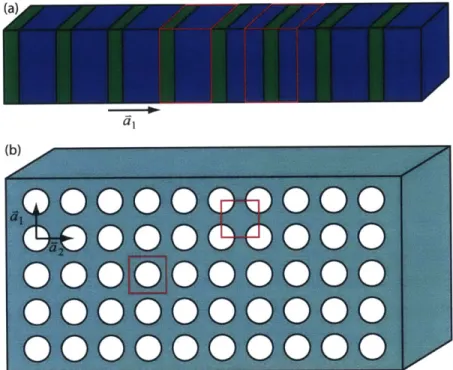
The first experiments I performed to this end were on photonic crystal slabs. The results of these experiments are detailed in chapter 4. Photonic crystals are optical analogs of semiconductor materials, and like semiconductors, they are crystals made up of a regular repeated units. However for photonic crystals, the carriers of interest are photons, which are essentially non-interacting particles, rather than electrons, which are charged particles that can interact with each other and the lattice by Coulomb forces. Using the improved imaging techniques that I developed, I used the polaritonics platform to directly visualize THz waves as they propagated through photonic crystal structures embedded in the LiNbO3 slab.
Examples of the structures studied are shown in figure 1-5(a). By taking advantage of the sensitivity of polarization gating imaging, I measured the wave vector-frequency dispersion curves of different photonic crystal lattices with different orientations. Removing the intra-particle interaction was especially useful for modeling, and comparing the results with theoretical calculations, as shown in figure 1-5(b), gave excellent agreement. In addition
to the bound states that were expected, leaky wave behavior was also observed. I was able to isolate different components of the Bloch waves that describe the photonic crystal eigenmodes, and subsequently reconstructed the spatiotemporal evolution of these different components.
(a)
(b)
0.8- 170.6-j 0 j 0 0 D O OO C 0r0.4-SC) 000 000000 S 0 0 0 Q 0 0 0 Q 0 0 (DQ 0.2-2)QQQOOOQQQQOC ---- O0 300 pm F M F KMK FFigure 1-5: (a) Examples of the photonic crystal lattices studied in this thesis. The two lattices shown are hexagonal arrays of air holes cut into a slab of LiTaO3 to form a photonic
crystal. The arrays have identical lattice constants and hole radii and differ only in their orientation relative to the THz wave propagation direction. (b) Measured wave vector-frequency dispersion curves for the photonic crystals are shown in (a). The left side of the F point corresponds to the crystal shown on top, while the right side of the F point gives the dispersion diagram of the crystal shown on the bottom. The red overlaid lines are calculations of the dispersion curves, and show excellent agreement with the experimental results.
The next set of experiments focused on carrier dynamics in inorganic materials. The first half of chapter 7 presents a collaboration with Prof. Rafael Jaramillo of MIT to study the lifetime of photoexcited charge carriers in tin (II) suflide (SnS). SnS is a semiconductor material with potential applications in solar cell devices. The main issue with solar cells made using SnS as the light absorber is that the the efficiencies of these solar cells are low
(< 5%) and this is believed to be linked to the lifetime of the electrons that are excited into
the conduction band within the material upon light absorption [31].
While studies have suggested different growth methods to improve the minority carrier lifetime [32], direct lifetime measurements for SnS has been been difficult as they require accurate modeling of the carrier dynamics and accurate measurement of the carrier con-centration. The use of THz frequency radiation to probe the excess carrier density through
carrier absorption provides us a direct measurement of the lifetime. By using time-delayed optical and THz pulses, I performed time-resolved THz measurements on a variety of SnS thin films grown under different conditions. The results showed an increase in the bulk car-rier lifetime when samples were annealed, supporting the hypothesis that annealing reduces the trap state density.
1018 800 nim pump ro0.07 ns No =1.0 x 1 Oi cm--S =2.37 x 101 cm/s 2. 1017 D =0.89cm2/s
c
400 nm pump Ne =2.2 x 1013 cm-101 0 0.02 0.04 0.06 0.08 0.1 0.12 0.14 0.16 0.18 0.2 time (ns)Figure 1-6: Time-resolved THz measurements on SnS. The red and blue curves represent traces obtained when SnS films are excited with 800 nm and 400 nm pump pulses. The variables of To, S, and D are related to the bulk and surface recombination rates as well as the carrier diffusivity in the film, and these values were extracted from fitting the experimental data.
The second half of chapter 7 details experiments I performed with Prof. Susan Dex-heimer of Washington State University, where we investigated the dynamics of carrier self-trapping in the one dimensional metal-halide chain complex, platinum iodide. One-dimensional metal-halide chains are model systems for studying carrier self-trapping, and have been studied extensively. The driving force for the self-trapping event is strong electron-phonon coupling which causes the crystal lattice to distort to stabilize a change in the charge density. This reduces the mobility of the carrier, as the heavier nuclei are now required to shift positions when the carrier arrives. Using the same technique as in the SnS measurement, as well as a fully resolved two-dimensional optical pump-THz probe mea-surement, the dynamics of the electron self-trapping event were monitored by following the conductivity of the material after optical excitation. The results were consistent with other published measurements of the structural and vibrational dynamics of this process [33,34]. These indicate that on the timescale of a phonon oscillation period, the lattice reorganizes in such a way as to localize the electron in the crystal, reducing the mobility and therefore
the conductivity of the material.
Finally, at the highest level of complexity, the last experiments that I performed were on a system where there are strong electron-electron, electron-phonon, and spin-lattice interactions. In this study, a correlated electron material, strain-engineered calcium-doped lanthanum manganite (LCMO), was studied using single-shot THz spectroscopy. At low temperature, strained LCMO exhibits a photoinduced insulator-to-metal phase transition, which persists for long times. Optical single-shot measurements performed by Dr. Sam Teitelbaum [35] and Dr. Jingdi Zhang [36] attempted to investigate the dynamics of this process by following the intensity of a charge-transfer resonance in the material. Their work showed an instantaneous decrease in the strength of the charge-transfer absorption, leading them to believe that there was a fast rise in the conductivity. By using single-shot THz spectroscopy, I was able to measure the dynamics of this event between 1 picosecond and 1 nanosecond following optical excitation. This demonstrated the first use of single-shot THz spectroscopy for following a quasi-irreversible process, and the resutls helped shed light on the mechanism of the photoinduced phase transition in this material.
(a) 4.5 (b)
N 4 2 s after pump 300 ps after pump
F = 6.1 mJ/cm2 F = 6.1 mJ/cm2
"1 3.5 <4
0 5 10 15 20 0 5 10 15 20
laser shot number laser shot number
Figure 1-7: Single-shot dynamics of a 30 nm film of LMCO. (a) Peak THz electric fields transmitted through the sample long (several seconds) after it was irradiated by the indi-cated number of 800 nm pump pulses. The first shot reports on a film that has not been optically pumped. (b) Peak transmitted THz fields recorded when the THz probe arrives at the LCMO film 300 ps after the last 800 nm pump pulse. The increase in the peak field
represents an increase in the transmission which is expected in the film.
The results of this work have led to the development of new methods for THz generation and detection, and have opened the door to new classes of THz measurements. Each of the remaining chapters provides the details of the experiments I described above, and will hopefully guide future generations of experiments in both free space and polaritonics studies.
Chapter 2
The Polaritonics Platform
On-chip control of terahertz (THz) fields in a slab of ferroelectric crystal, termed THz polaritonics [6], has its roots in some of the original work on generation of ultrashort pulses of THz frequency radiation. In some of the pioneering work in the field, Auston and co-workers used ultrafast pulses to both generate and detect THz transients in the ferroelectric crystal, lithium tantalate [37]. Although this methodology was successful for generation, propagation, and detection of THz fields in a single piece of material, other methods for THz generation became more widespread because of the capability for transmitting signals through free space [1, 38]. Polaritonic generation was limited in this respect because poor phase matching between the driving field and the resultant THz response did not allow for significant amplification of the field. This problem appeared to be worsened by the fact that coupling losses of the radiation from the host material into free space led to a significant reduction in the field amplitude.
Despite these facts, and in some cases because of them, the platform proved an invaluable method for studying phonon-polaritons in media in which they originated. As result of the improved understanding and experimental capabilities, the field of THz polaritonics has experienced significant growth and development within the last 15 years. The platform as it exists today typically consists of a single slab of thin (30-50 Rm thick) ferroelectric crystal within which all of the aspects of the measurement take place. In many respects, the unique geometry of the polaritonics platform presents advantages compared to the free-space configuration. As it is possible to generate and and detect THz waves all on a single piece of material, this system avoids any free-space coupling loses that are typically present
in THz experiments. Generation of THz fields is accomplished by propagating ultrashort optical pulses in either lithium niobate (LN, LiNbO3) or lithium tantalate (LT, LiTaO3). Through impulsive stimulated Raman scattering (ISRS) [7], this leads to the generation of phonon-polaritons which are admixtures of electromagnetic radiation, in this case at THz frequencies, and polar lattice vibrations. It is these quasiparticles that are the "signal carriers", unlike electrons which are used for transmitting signals in slower conventional electronics, or photons which mediate signals in photonics. Detection of the fields is possible because the host materials are electro-optic, meaning that their optical properties respond to the presence of electric fields including those of the THz electromagnetic radiation trapped within the material. Furthermore, the THz fields may be controlled or enhanced by spatial and temporal control of the driving optical fields [39,40]. It is also possible to introduce a variety of photonic components by machining structures into the slab [8-18], or depositing structures onto the surface [19,20], enabling not only the study of the polariton waves, but also their interactions with different structures.
In this chapter, I will discuss several of the details of the polaritonics platform. I will begin by describing the phonon-polariton dispersion and discuss how this relates to THz generation. Following this, I will discuss the generation of phonon-polaritons in the standard polaritonics media. Finally, I will discuss the details of the electro-optic effect as it relates to the detection of THz waves.
2.1
Dispersion Relation of Phonon-Polaritons
In general, a polariton is a quasiparticle that results when electromagnetic radiation is strongly coupled to an elementary degree of freedom within a material. Most relevant for THz polaritonics, the electromagnetic field couples to low frequency transverse optic (TO) phonons which are collective motions of the ions in the unit cell; the resulting quasiparticles are phonon-polaritons. This can be understood for both LiNbO3 and LiTaO3 since they
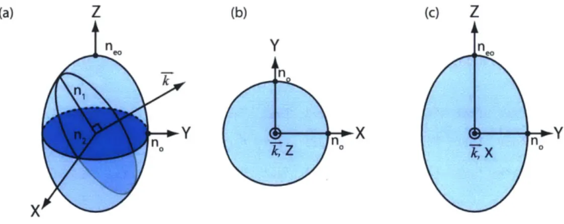
are uniaxial ferroelectric crystals. The fact that they are uniaxial means that they have one crystal axis which is unique compared to the other two. That they are ferroelectric means they also possess a static dipole moment. For uniaxial materials, the optic phonon modes can be classified as either ordinary, of which there are two, or extraordinary, of which there is one. In the appropriate reference system, known as the principal axis system, the two
classes can be completely decoupled and treated independently. In this reference system, the extraordinary axis is also referred to as the optic axis or the c-axis. The most relevant phonon mode in this case is the extraordinary TO phonon as electromagnetic radiation is
able to couple to the TO phonon through a dipolar interaction.
In order to describe the phonon-polaritons, it is necessary consider the effect that a time-varying electric field, Eo exp(-iwt), has on the system [41]. The displacement of the ions in the lattice in response to the applied field can be represented by the value Q(t). Assuming that the field is slowly varying with respect to the unit cell, this interaction can be simply modeled by a damped Lorentzian oscillator that is driven by the electric field,
Q(t)
+
FO(t)+ A1Q(t)
= A2E(t), (2.1)where
F
is a damping constant and A1 and A2 are constants whose physical significancewill become clear later. By taking advantage of the fact that the solutions are expected to be time-harmonic, we can write Q(t) = Qo exp(-iwt). As a result, equation (2.1) can be
Fourier transformed to solve for
Q(w)
as a function of E(w):A2E(w)
--(w 2 + ifw - A,) (2.2)
As equation (2.2) is the solution for a damped driven oscillator, we can conclude that
A1 = w where WT is the transverse optic phonon frequency. For the extraordinary waves,
WT/27r = 7.4 THz and 6.0 THz in LiNbO3 and LiTaO3, respectively; for the ordinary waves,
the frequencies are wT/27r = 4.6 THz in LiNbO3 and 4.3 THz in LiTaO3 [42,43].
In driving the motion of the oscillators, the presence of the electric field induces a polarization P(-, t) within the material. In the linear response regime, this polarization can be related to the electric field in the frequency domain by
P(w) = foX()E(w), (2.3)
where Eo = 8.85 x 10⁻¹² C2 N-1M 2 is the permittivity of free space. =(W) is the frequency dependent susceptibility and is related to the dielectric tensor =(w) by =(w) = =(w) - 1. In
general the responses may be anisotropic and thus the dielectric response, a rank-2 tensor, is most appropriately written as a 3 x 3 matrix. However, separating the ordinary and
extraordinary optic phonons by choosing the principal axis system also diagonalizes the dielectric tensor. As such we can treat the equations independently and treat the dielectric constant as a scalar rather than a tensor. In this case, the resulting polarization can also be viewed as a sum of contributions from the applied electric field as well as the field resulting
from the displaced ions within the material:
P(w) = Eo(E(w) - 1)E(w) = BiQ(w) + B2E(w). (2.4)
Substitution of Q(cw) using (2.2) and isolating for E(w) gives an expression for e(w):
+B2 +1 [2B1 A2(25
COw
=O +-T -2W2 . (2.5
The unknown constants A2, B1 and B2 can be related to physically measurable quantities by examining the high frequency (w -+ oo) and low frequency (w - 0) limits. In the first
case:
B2
E(W - oo) = E, = 1+ - =- B2 =o(-1). (2.6)
60
In the low frequency limit,
B2
1
BA2 E0o + 1 B1A2(2.7)
E(W =0) = 6L= 1+ 0+- =6+- W . (2.7)
By conservation of energy arguments (see Appendix V of [41] for a rigorous proof), the
remaining constants can be shown to be equivalent, reflecting the symmetry between the coupling of electromagnetic waves to the lattice and the corresponding contribution of the lattice to the polarization,
B1 = A2 = WT Vo(L - EO), (2.8)
= If. (2.9)
f
= WT(eL - E,) represents the coupling strength between the field and the lattice. Col-lecting these, a single closed form expression for the dielectric constant can be writtenW(2(oEL - o()
E (W) = 6"c + _2 T 2 .(2.10)
As both LiNbO3 and LiTaO3 are nonmagnetic media, the frequency-dependent refractive
index is related to this dielectric function by n(w) =
Ve(w).
This can be used to relate the wave vector k to the frequency w to give polariton dispersion curves:W k = n(w),
co
W LIr2(EL - Eoo)
= o + 2 T-2 - , (2.11)
where co is the speed of light in vacuum.
The dispersion curves for extraordinary phonon-polaritons in LiNbO3 and LiTaO3 are
plotted in figure 2-1, along with the frequency-dependent dielectric constants and refractive indices. The polariton dispersion curves are calculated without (F = 0) and with (finite
F)
damping. In both cases, coupling between the phonon mode and the electromagnetic field leads to an avoided crossing between two states, known as the lower and upper polariton branches. Comparing these curves for two materials, there is a larger splitting between the two branches in LiTaO3 compared to LiNbO3, which is also reflected in the coupling
strength (fLT ~ 42600 THz2, fLN ~~ 34500 THz2).
It is important to realize that the dispersion relationship plotted here represents neither a pure photon nor a pure phonon, but rather the quasiparticle hybrid of the two. What this means on a microscopic level is that the two entities cannot be separated, since the electromagnetic radiation that is propagating through the material causes the lattice to oscillate because of the field-dipole coupling. Alternatively, one can instead consider the lattice vibration to be moving through the material, but as this vibration causes ions to oscillate, there is a radiated field that travels with it.
Along the upper polariton branch, the dispersion is said to be "photon like" at large wave vector, as the frequency grows linearly with wave vector. At low wave vector, the dispersion is "phonon-like" and the frequency approaches the longitudinal optic phonon frequency WL'-This occurs when e(w) = 0 and can be related to the other physical properties of the system
through the Lyddane-Sachs-Teller (LST) relation [44,45]
WL = T EL (2.12)
20 15 N 10 C a) 5) 0 20 15 N 10 5 200 400 wave vector (mm-1) (a) LiNbO3 c/n. c/no c ---(d) LiTaO3 c7/n c/no r > 0 - = 0 b) - - -H-- - -e) - Re[c(o)] - Im[E(o)] 0 100 200 dielectric constant 5 10 index of refraction n n. (c) I I - - ---- --n n (f) | Re[n(o)] - Im[n(o)] 15
Figure 2-1: Dispersion relations, dielectric function, and refractive index for of extraordi-nary phonon-polaritons in LiNbO3 (a, b, c) and LiTaO3 (d, e, f). (a, d) The polariton
branches plotted with and without damping, F. The lower-polariton branch approaches the transverse optic phonon, WT/27r as k -> oc. The upper-polariton branch approaches the lowest-frequency longitudinal optic phonon at WL/27r at zero wave vector. The straight lines represent the light lines for uncoupled electromagnetic waves. The large difference in the dielectric constants for LiTaO3 leads to a larger splitting between the upper and
lower polariton branches compared to LiNbO3. (b, e) The real and imaginary parts of the dielectric function when FLN =
0.63
and FLT = 0.84. (c, f) The corresponding real and imaginary parts of the refractive index.to be "light-like" as the frequency depends roughly linearly on the wave vector with a slope set by the low-frequency dielectric constant,
EL.
At large wave vector, the polaritons become more "phonon-like". When there is no damping, the dispersion curve asymptotically approaches WT. The inclusion of damping leads to non-asymptotic behavior resulting from the anomalous dispersion. For typical experiments, we focus on the lower polariton branch in the region where the index is roughly constant. For LiNbO3 this corresponds to w/27r < 2.5THz where Te0 ~ 5, and for LiTaO3 we are restricted to w/27r < 1.5 where ieo ~ 6.2. A
table of relevant constants at THz frequencies for LiNbO3 and LiTaO3 is given below, as
32
I
11.9 THz 7.4THz 13.3 THz 6.0 THz IV 0well as the group refractive index at 800 nm.
Table 2.1: THz frequency constants of LiNbO3 and LiTaO3
Material Crystal Axis wT/ 2
7r (THz) WL/27r (THz) 6L Eo, r' nSoo"n
LiNbO3 ordinary 4.6 6.7 41.5 19.5 0.42 2.36 extraordinary 7.4 11.9 26.0 10.0 0.63 2.25
LiTaO3 ordinary 4.3 6.7 41.5 17.4 0.42 2.23 extraordinary 6.0 13.3 37.6 7.6 0.84 2.24
2.2
THz Generation on the Polaritonics Platform
The generation of THz frequency phonon-polaritons is possible in LiNbO3 and LiTaO3 because of the interaction of an ultrafast laser pulse with a polar lattice vibration [7]. In the language of nonlinear optics, this coupling leads to the generation of a polarization in the host material, similar to what was described previously. Because of the large amplitude of the E-field of the ultrafast pulse, the material response becomes nonlinear, and the resulting polarization can be expanded in powers of the applied field
_t+=(2) -2 (3) 3t .
P(t) = ) + E ( + E
= EoX(1)$(t) + PNL(t) (2.13)
The sum of the contributions of these effects is typically written in terms of the displacement field D, which can be related to the local electric field, E through the constitutive relation
D(t) = coE(t) + P(t),
=(1 )o -1 (t) + NL ()
=0
Z(t)
+NNL ()E= I5LP ) (2.14)
The first term represents the linear response of the material while all higher order terms represent nonlinear responses. Relevant for THz generation is the second-order nonlinear
=(2)
response and the associated susceptibility tensor, X , a rank-3 tensor which can be rep-resented as 3 x 3 x 3 matrix. It possesses 27 elements labeled Xijk (i, j, k = {1, 2, 3}), of
nonzero, allowing for second order processes such as sum or difference frequency generation. Both LiNbO3 and LiTaO3 are non-centrosymmetric materials and are particularly useful
in polaritonics because of their large nonlinear responses. Compared to the conventional zincblende materials zinc telluride (ZnTe) or gallium phosphide (GaP), LiNbO3 and LiTaO3
have a significant ionic contribution to their susceptibility [37] leading to large nonlinear responses.
2.2.1 Optical Rectification and the Nonlinear Wave Equation
THz generation occurs by optical rectification, a second order process similar to difference
frequency mixing. The nonlinear polarization resulting from this interaction can be written as
-- (2)(2)
P(F Q)L =EO ( W1 - W2)E1(r', 1) *E 2(-,W2) , -)
-+i(i, t)NL = 60=(2) (.6
The two fields in the above expression belong to the same pulse, E1 = E2, and since
P(i,
t)oc
El (r-, t)E2 (T', t), the polarization matches the envelope of the pulse only. Physically, this nearly static polarization results from the various frequency components of the pulse mixing with each other. The maximum Q is set by the bandwidth of the pulse which is inversely proportional to the transform limited pulse duration. For 100 fs pulses, the theoretical maximum max 10 THz.-This nonlinear polarization can act as a source in Maxwell's equations. To see this, we write a wave equation in the usual way starting from Faraday's Law and Ampere's Law:
a
V x E(f, t) = -po tH(r, t), (2.17a)
V x
I(F,
t) = D (r, t), (2.17b)where we have assumed a medium without free currents or charges (pf = Jf = 0). Taking
the curl of equation (2.17a) and substituting (2.17b) gives
V2 E
By using the constitutive relation in equation (2.14), D can be eliminated from the right hand side to give the nonlinear wave equation:
9(1)
02 1 a2 t
V x V x E(r-,t) + E (r, t) = PNL
c0 e9t2 60cO t2
The =(l) factor on the left hand side corresponds to the linear dielectric tensor for the resulting waves in the nonlinear medium and dictates how they would propagate in the absence of a source. This equation resembles the wave equation in linear media, except that the nonlinear polarization acts as a source for generating waves. The left hand side can be made to look more familiar by using the identity V x V x F = V(V - E) -
V
2E.For linear, homogeneous media the first term on the right vanishes by Gauss' Law, however this is not required to be so in nonlinear materials. Still, it can be dropped in many cases of interest in nonlinear optics when the slowly varying envelope approximation is valid [46]. Substituting for the source term using equation (2.16):
2(1)0 2 1. =(2) 92 t) .2
V2E(-,t) -
g
(rt) = -2T Es(2,t) . (2.20)2.2.2 Solutions to the Nonlinear Wave Equation in LiNbO3 and LiTaO3
- Cherenkov Radiation
The solutions to the nonlinear wave equation describe how a field resulting from a nonlinear
polarization propagates within the medium following generation. The polarization P(r-, t)
acts as a source that propagates through the LiNbO3 or LiTaO3 with a group velocity
V = c/ng. At any instant, the polarization generates a spherical wave of THz radiation,
which propagates at a velocity vTHz c/n THZ which is different from the velocity of the
source. As vTHZ < v, the THz fields are produced as Cherenkov radiation
[47-50].
The relative angle between the the phase fronts of the resulting wave and the direction of the source is defined as the Cherenkov angle, 0c, given by cos(6c) = VTHz/V.To see this formally, we must solve equation (2.20). The solution can be obtained through the use of the Hertz vector potential, H(-, t) [47,49,51]. Generally, when the wave equation has a polarization term as a source the electric field E is obtained by solving the