HAL Id: tel-00136102
https://tel.archives-ouvertes.fr/tel-00136102
Submitted on 12 Mar 2007
HAL is a multi-disciplinary open access
archive for the deposit and dissemination of sci-entific research documents, whether they are pub-lished or not. The documents may come from
L’archive ouverte pluridisciplinaire HAL, est destinée au dépôt et à la diffusion de documents scientifiques de niveau recherche, publiés ou non, émanant des établissements d’enseignement et de
Stability of carbon nanotubes and fabrication and
mechanical properties of carbon nanotube based
composites
Genwei Wang
To cite this version:
Genwei Wang. Stability of carbon nanotubes and fabrication and mechanical properties of carbon nanotube based composites. Mechanics [physics.med-ph]. École normale supérieure de Cachan - ENS Cachan, 2006. Chinese. �tel-00136102�
ENSC-
THESE DE DOCTORAT
DE L’ECOLE NORMALE SUPERIEURE DE CACHAN
Présentée par Monsieur Genwei WANG
Pour obtenir le grade de
DOCTEUR DE L’ECOLE NAORMALE SUPERIEURE DE CACHAN
Domaine
Mécanique- Génie Mécanique Génie Civil
Sujet de la these:
Stabilité du Nanotubes de Carbone; Fabrication et Comportement Mécanique du Composites à Base des Nanotubes
Thèse présentée et soutenue à Beijing le 08 mai 2006 devant le jury compose de:
Jinbo BAI Professeur Président & Rapporteur
Gengkai HU Professeur Rapporteur
Yapu ZHAO Professeur Examinateur
Longmao ZHAO Professeur Examinateur
Xuefeng SHU Professeur Examinateur
Han ZHAO Professeur Directeur de thèse
太 原 理 工 大 学 博 士 学 位 论 文
碳纳米管稳定性及其复合材料的制备
和力学性质
学科专业
固体力学
研究方向
纳米材料力学
研 究 生
王根伟
指导教师
杨桂通教授 赵亚溥研究员 (中国)
赵 涵教授 (法国)
培养单位
太原理工大学应用力学研究所
Stability of Carbon Nanotubes and
Fabrication and Mechanical Properties
of Carbon Nanotube Based Composite
Dissertation Submitted to
Taiyuan University of Technology
and
Ecole Normale Supérieure de Cachan
In partial fulfillment of the requirement
for the Doctoral Degree of Philosophy
by
Genwei WANG
Dissertation Supervisor: Prof. Guitong YANG (China)
Prof. Yapu ZHAO
(China)
Prof. Han ZHAO (France)
Institute of Applied Mechanics, Taiyuan University of Technology
LMT Cachan, Ecole Normale Supérieure de Cachan
碳纳米管稳定性及其复合材料的制备和力学性质研究
摘
要
碳纳米管由于其高强度,低密度,大长细比,铜和硅的导电性,金
刚石的导热性,DNA的尺寸,碳的化学性质,一经发现就受到了异乎寻
常的关注,其独特的性质使得碳纳米管无论作为功能材料还是结构材料
都有着极为广泛的潜在应用。本文从碳纳米管在NEMS结构和复合材料的
应用出发,研究了碳纳米管在自重以及在纳米开关范德华力作用下的吸
合稳定性,制备了基于碳纳米管的微米
/纳米杂交强化复合材料,并对复
合材料在动静态压缩载荷作用下的力学响应进行了实验研究,取得了以
下成果:
1)借助连续介质力学的柱(梁)理论研究了单壁碳纳米管在自重作用
下的稳定性。通过使用量纲分析,找到两个控制碳纳米管长细比
lcr/R的
无量纲数
ρgR E/和
t R/。力学分析确定了长细比
lcr/R与无量纲数
ρgR E/和
t R/的关系。通过理论分析发现碳纳米管在自重作用下的临界长细比
/ cr l R高达10
6。
2)使用双悬臂梁模型,利用大变形理论建立了范德华力作用下具有
碳纳米管-碳纳米管结构的吸合非线性方程,用Galerkin方法对方程组进
行了离散,并用Newton -Rhapson方法进行了数值求解。通过分析碳纳米
管轴线挠度的斜率来确定吸合点,对碳纳米管间的距离,内径,吸合长
度等进行了详细分析,为基于碳纳米管的NEMS结构设计提供参考和指
导。
3)用流动化学气相沉积法在平均直径4微米的SiC颗粒上制备了多壁
碳纳米管,通过机械搅拌,将不同含量的SiC/CNT与环氧树脂混合,通过
抽真空,注入模具,室温固化,高温固化,切割等步骤,做成了微米/纳
米杂交强化的复合材料。
4)利用制备好的杂交强化复合材料圆柱形试件,在MTS810试验机
上进行了准静态压缩实验,得到了不同体积含量的材料压缩强度和弹性
模量。静态压缩实验表明真空度对复合材料强度有着很重要的影响。
5)用分离式Hopkinson压杆首次对杂交强化复合材料试件进行了动
态压缩实验。将动态实验结果与静态实验结果进行了比较,发现由于
SiC/CNT杂交强化作用,动态屈服强度的提高大于静态屈服强度的提高。
6)用SEM对动静态压缩实验后的试件破坏界面进行了观察,发现由
于有SiC颗粒做载体,没有发生通常碳纳米管增强复合材料中常见的碳纳
米管团聚现象,碳纳米管在基体内有很好地分散。电镜观察还发现碳纳
米管与碳化硅颗粒之间的连接强度比较弱,成为影响复合材料强度的一
个不可忽视的因素。
关键词 碳纳米管,稳定性,纳米开关,吸合,复合材料,制备,压缩
实验
STABILITY OF CARBON NANOTUBES
AND FABRICATION AND MECHANICAL
PROPERTIES OF CARBON NANOTUBE
BASED COMPOSITE
ABSTRACT
Since its discovery, carbon nanotube (CNT) has captured exceptional
attention from physicists, chemists and materials scientists alike. Its
extraordinary properties, high strength, low density, huge aspect ratio,
electrical conductivity of copper and silicon, thermal conductivity of diamond,
size of DNA, the chemistry of carbon, hold great promise for enormous
potential application in both functional and structural direction. In this paper,
for the application of carbon nanotubes in NEMS, the stability of carbon
nanotube under its weight and the pull-in stability of carbon nanotube based
nanoswitch structure are studied. A CNTs reinforced micro/nano multiscale
hybrid composite is fabricated and its mechanical properties are invstigated
by static and dynamic compressive test. The obtained results are outlined as
following:
a) By using continuum rod model, the stability of single walled carbon
nanotube under its weight is studied. Two dimensionless numbers,
ρgR E/and
t R/, which govern the aspect ratio of carbon nanotube, are found by
dimension analysis. Research results show that the critical aspect ratio can
reach to the order of 10
6.
b) Double cantilevered model with large deformation is used to construct
nonlinear pull-in equations for carbon nanotube-carbon nanotube based
structures. Galekin method is applied to discretize the equations and
numerical simulation is carried out to solve the nonlinear equations by
New-Phapson iteration method. This pull-in instability study offers data on
the nanotube gap size and length for nanoswitch design.
c) Floating chemical vapor deposition (CVD) method is used to grow
aligned multiwalled carbon nanotubes on the surface of SiC particles with an
average size of 4 μm. Different loadings of SiC/CNT are added into epoxy
matrix by mechanical blending. Carbon nanotube reinforced micro/nanoscale
hybrid composite specimens are made after the processes of vacuum, infusing,
ambient temperature solidification, high temperature solidification and
cutting.
d) As prepared composite cylindrical specimens are studied by static
compressive test with MTS810 material experimental machine. The
compressive strength and elastic modulus are obtained. Static compressive
experimental results show that vacuum has very important influence on the
strength of composites.
e) Dynamic compressive test is made for the first time to investigate the
strength of hybrid composites with split Hopkinson press bar. Comparison
with static results, the increment of strength under dynamic impact is bigger.
f) SEM observation on the fracture surface shows that carbon nanotubes
are dispersed homogeneously. No aggregation of carbon nanotube is found
due to SiC acting as a carrier. The aggregation usually appears in carbon
nanotube reinforced composites. It is also found that bad link between carbon
nanotubes and SiC particles exists, which has impressive influence on the
strength of composites.
KEY WORDS: Carbon nanotube, stability, Nanoswitch, Pull-in, composite,
STABILITY OF CARBON NANOTUBES
AND FABRICATION AND MECHANICAL
PROPERTIES OF CARBON NANOTUBE
BASED COMPOSITE
SYNTHESIS
Introduction
The discovery [1] of carbon nanotubes (CNTs) has provoked enormous interest in their fundamental behavior and potential applications. Researchers [2, 3] have envisioned CNTs as the most viable candidates to dominate the coming 21st century revolution in nanotechnology. Carbon nanotubes can be thought of as rolled up sheets of graphite that are sometimes capped on each end, with structures that vary depending on the conditions under which they are synthesized. There are two basic types of nanotubes. Single walled nanotubes (SWNTs) have one shell of carbon atoms in a hexagonal arrangement. Multiwalled nanotubes (MWNTs) consist of multiple concentrically nested carbon tubes. Each type has its advantages and disadvantages. MWNTs are easier and less expensive to produce, whereas current synthesis methods for SWNTs result in a great deal of concentrations of impurities that require removal by acid treatment. On the other side MWNTs have a higher occurrence of structural defects than SWNTs, which diminishes their useful properties.
Although there are varying reports in the literature on the exact properties of carbon nanotubes, theoretical and experimental results have shown extremely high elastic modulus, greater than 1 TPa and reported strengths 10–100 times higher than the strongest steel at a fraction of the weight. CNTs is the preferred choice for building block for supporting system for the space elevator.
The rapid growth of the micro/nano scale fabrication technologies in recent years leads to various development of Micro/Nanoelectromechanical systems (MEMS/NEMS).
Cantilever-based MEMS /NEMS structures such as microcantilever sensors [6, 7], microaccelerometers [8], atomic force microscope (AFM) [9], microswitch [10] etc are widely used.
Nanotweezer is one of carbon nanotube applications. Kim and Lieber [11] are the first to attach two carbon nanotube bundles to a tapered glass structure to fabricate a nanoscale tweezers. Voltage is applied to the electrode to open and close the free ends of the cantilever nanotubes. Akita [12] et al attaches two carbon nanotubes on the metal electrodes patterned on a conventional Si tip to fabricate such nanotweezers.
The Stability of a vertical SWNT under its own weight
[13]During of the applications of CNTs, an isolated and long carbon nanotube will offer more opportunities. The stability of carbon nanotube under its own weight is a practical problem. The critical length of the arm (CNT) is a crucial parameter for the design of tweezers-like NEMS structure.
A vertical SWNT under its own weight, with the lower end clamped, is schematically shown in Fig 1. By using dimensional analysis, three independent dimensionless numbers,
/
cr
l R , /ρgR E, t R/ , were found. lcr/R is the critical aspect ratio, ρgR E/ ratio of
gravity to elastic resilience, t R/ ratio of half wall thickness to radius of SWNT. The
relationship of three dimensionless numbers was found by elastic column model as
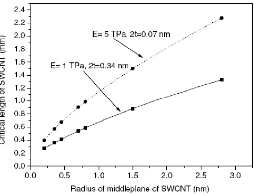
3 2 3.92 1 cr l E t R ρgR R ⎡ ⎤ ⎛ ⎞ = +⎛ ⎞ ⎢ ⎜ ⎟ ⎥ ⎜ ⎟ ⎝ ⎠ ⎝ ⎠ ⎢⎣ ⎥⎦ (1) It was found that the ratio lcr/R , which increases almost linearly with t R/ , is very large (in the order of 106) because of the high Young’s modulus and low density (see Fig. 2). The influence of the dimensionless number ρgR E/ on the vertical stability of SWNT is showed in Fig. 3. The analytical result shows that as the dimensionless numberρgR E/ increases, the critical ratio lcr/R must decrease to maintain its stability of SWNT.
Several actual calculation samples of different radii of middle plane and critical lengths of SWNT are showed in Table 1 and Fig. 4.
The pull-in Stability study of nanotubes under van der Waals
forces influence
[14]As the structure scale reaches micro/nano scale, the forces like Casimir [15], van der Waals [16, 17] forces plays much more important influence on the structures. Dequesnes [17] et al studies the cantilever nanotube pull-in instability under van der Waals and electrical forces influence. Their van der Waals force is nanotube -substrate force, which is not applied to nanotweezers’ nanotube-nanotube structure. During their derivation of van der Waals force, the thickness of the single-wall carbon nanotube structure is not reflected as a parameter in their van der Waals force expression. Rotkin [18] obtains the analytical solution of the nanotube-substrate system by modeling the system as one degree of freedom system and setting the first, second derivatives of the system total energy to be zero. As the nanotube-substrate structure also forms capacitance-like structure, the electrical force together with vdW force is included in Rotkin’s model. A more general model is presented to calculate the van der Waals force by considering the nanotube interior and exterior radii influence (i.e. thickness) and modeling the nanotube as continuous system.
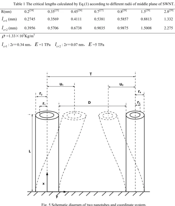
For the two cantilevered SWNTs under van der Waals force in Fig. 5, the governing equations are ) , ( 2 0 1 2 2 1 21 2 1 41 4 1 dx f u u x u x u L EA x u EI L ⎟ + vdW ⎠ ⎞ ⎜ ⎝ ⎛ ∂ ∂ ∂ ∂ = ∂ ∂
∫
, (2) ) , ( 2 0 1 2 2 2 22 2 2 42 4 2 dx f u u x u x u L EA x u EI vdW L + ⎟ ⎠ ⎞ ⎜ ⎝ ⎛ ∂ ∂ ∂ ∂ = ∂ ∂∫
, (3)where E is Young’s modulus, u1, u2deflections of SWNTs, A1, A2 areas of cross section,
L the length of SWNT.
equations. L x = ξ , T u U1 = 1, T u U2 = 2 , T r1 = β ,
( )
72 1 4 2 2 E rT AL = η . (4)Here η only indicates the order of the ratio of van der Waals energy to nanotube bending energy, not the actual ratio because the critical parameter, the thickness is not shown in η.
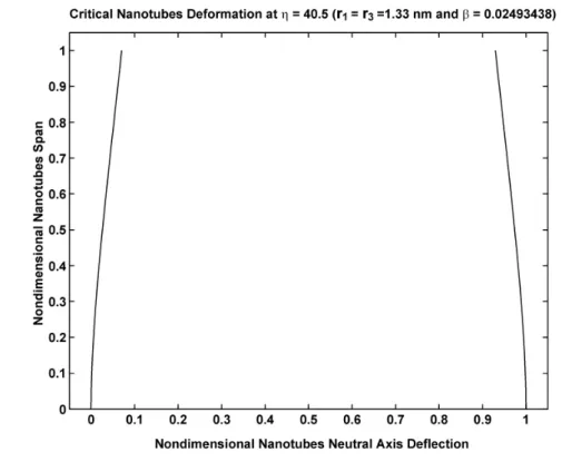
In order to compute the coupled nonlinear equations, Galerkin method was applied to discretize the two equilibrium equations. Newton-Rhapson method is applied to solve the discretized nonlinear equations. Several results are showed in Fig. 8-11.
This pull-in instability study offers the data of the nanotube gap size and length for nanotweezer design. The model accounts the large deformation as a nonlinear part in the governing equations, which can be easily extended to the study of other structures under van der Waals force influence.
Fabrication and mechanical properties of micro/nanoscale
hybrid composite
[19]Another most important application of CNTs is nanocomposite. Composite is a complex material, in which two or more chemically distinct materials with a distinct interface combine to produce new structural or functional properties that cannot be achieved by any of the components acting alone. Owing to its unexampled advantages over many traditional materials, the research and application of composite are developed rapidly. CNTs’ superior mechanical properties (strength and ductility), high aspect ratio, low density, good thermal and electronic conductivity make them attractive candidates as a reinforcement filler material. CNTs offer an appealing mechanism to dramatically improve both strength and stiffness characteristics, as well as add multifunctionality to polymer based composite systems. Recently research on multiscale hybrid materials with CNTs included has arisen [20-22]. It has been proved that the existence of carbon nanotubes could
greatly improve the interfacial strength between fiber or particle and matrix [20, 21]. Most of them focus on fabrication of materials and simple tensile tests. To my knowledge, static and dynamic compressive experimental results for this kind of composite are still unavailable.
Herein, we fabricate a micro/nanoscale hybrid composite, in which SiC particle of average 4 micron with multiwalled carbon nanotubes grow on were mechanically blent with epoxy resin. Static and dynamic compressive tests were made to study compressive response of both specimens with and without SiC/CNT.
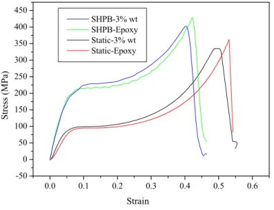
Chemical vapor deposition (CVD) method was used to grow aligned multiwalled carbon nanotubes on the surface of SiC particles at 650 - 750 ℃ [21]. Fig. 10a shows a scanning electronic microscope (SEM) image of as-received SiC particles with an average size of 4 μm. These particles are irregular in shape and have several flat surfaces. Fig. 10b display a low magnification SEM image of typical product. Carbon nanotubes are aligned and perpendicular to some of flat surfaces. Weight proportion of SiC particle and carbon nanotube is about 3±0.2 : 1. They are 10 - 20 μm long. Fig. 10c are enlarged image of carbon nanotubes grown on SiC particles. They are 10 - 50 nm in diameter. 3% wt SiC/CNTs were first dispersed in the liquid epoxy. The suspension was mechanically stirred for 40 minutes and degassed for 10 minutes. After adding hardener, the suspension was stirred for 10 minutes and degassed for 10 minutes again. At last the solution was fallen over the cylindrical mold, vacuumed for 30 minutes. The specimens were first solidified at room temperature for 24 hours, then increased temperature to 60 ℃ and held for 12 hours. At last temperature was increased to 90 ℃ and held for 24 hours. Pure epoxy specimens were made for comparison. The dimensions of cylindrical specimens are 10 mm in length and 10 mm in diameter.
3% wt SiC/CNT were filled in epoxy resin, good electric conductivity achieved. Static compressive tests were conducted on material testing machine (MTS 810) at a loading rate of 0.01 mm/s. Split Hopkinson press bar (SHPB) is a commonly used experimental technique to study constitutive laws of materials at high strain rates [23]. It is showed in Fig.
11. 10 m/s was chosen as impact speed for dynamic compressive tests. Dynamic fracture surface of 3% wt SiC/CNT specimen is shown in Fig. 10d. It can be seen that part of carbon nanotubes grown on SiC particle were taken off, which means bad link between SiC particle and carbon nanotubes exists. Fig. 12 shows the typical static and dynamic compressive stress – strain curves of the specimens with and without SiC/CNT. Young’s modulus increases (from 1708 MPa to 2202 MPa) by 30% with 3% wt SiC/CNT from the static test. But for dynamic test, the equivalent Young’s modulus hardly changes. Increments of strength of both static and dynamic compressive test are shown in Fig. 13. It is clear that Increment of strength under dynamic loading is bigger than under static loading.
References
[1] Iijima S. Helical microtubules of graphitic carbon. Nature, 1991, 354: 56-58
[2] Dresselhaus M S, Dresselhaus G and Jorio A. Unusual properties and structure of carbon nanotubes. Annual Review of Materials Research, 2004, 34:247-278
[3] Ajayan P M and Zhou O Z. Applications of carbon nanotubes, in Carbon Nanotubes Synthesis, Structure, Properties and Applications (eds. Dresselhaus M S, Dresselhaus G and Avouris Ph), Springer Publications, 2001, 80:391-425.
[4] Qian D, Wagner G J, Liu W K et al. Mechanics of carbon nanotubes. Applied mechanics reviews, 2002, 55: 495-599.
[5] Edward B C. Design and deployment of a space elevator. Acta Astronautica, 2000, 47(10): 735-744
[6] Thundat T, Oden P I and Warmack R. J. Microcantilever sensors. Microscale Thermophysical Engineering, 1997,1: 185-99.
[7] Du L, Kwon G, Arai F, Fukuda T, Itoigawa K and Tukahara Y. Structure design of micro touch sensor array. Sensors and Actuators A, 2003, 107: 7-13
[8] Kovacs A and Vizvary Z. Structural parameter sensitivity analysis of cantilever and bridge -type accelerometers. Sensors and Actuators A, 2001, 89: 197-205.
[9] Ishikawa M, Yoshimura M and Ueda K. Carbon nanotube as a Probe for friction force microscopy. Physica B, 2002 , 323: 184-6.
Diamond microwave relay. Diamond and Related Materials, 2002, 11: 672-6. [11] Kim P and Lieber C M. Nanotube nanotweezers. Science, 1999, 286: 2148-50.
[12] Akita S, Nakayama Y, Mizooka S, Takano Y, Okawa T, MiyatakeY, Yamanaka S, Tsuji M and Nosaka T. Nanotweezers consisting of carbon nanotubes operating in an atomic force microscope. Applied Physics Letters, 2001, 79: 1691-3.
[13] Wang G W, Zhao Y P and Yang G T. The stability of a vertical single-walled carbon nanotube under its own weight. Materials & Design, 2004, 25:453-457
[14] Wang G W, Zhang Y, Zhao Y P and Yang G T. Pull-in stability study of nanotubes under van der Waals forces influence. Journal of Micromechanics and Microengineering, 2004, 14:1119-1125.
[15] Buks E and Roukes M L. Stiction adhesion energy and casimir effect in micromechanical systems. Physical Review B, 2001, 63: 033402.
[16] Lin W H and Zhao Y P. Dynamics behavior of nanoscale electrostatic actuators. Chinese Physics Letters 2003, 20: 2070-3.
[17] Dequesnes M, Rotkin S V and Aluru N R. Calculation of pull-in voltages for carbon-nanotube-based nanoelectromechanical switches. Nanotechnology, 2002, 13: 20- 31.
[18] S.V. Rotkin, Theory of Nanotube Nanodevices, in Nanostructured Materials and Coatings for Biomedical and Sensor Applications (eds. Gogotsi Y G and Uvarova I V), Kluwer, 2003: 257-277.
[19] Wang G W, Zhao H, Bai J B and Zhao Y P. Fabrication and mechanical properties of micro/nanoscale hybrid composite. Appear in 1st IEEE International Conference of Nano/Micro Engineered and Molecular Systems. 2006, Zhuhai.
[20] Thostenson E T, Li W Z, Wang D Z, Ren Z F, and Chou T W. Carbon Nanotube/Carbon Fiber Hybrid Multiscale Composites. Journal of Applied Physics. 2002, 91:6034-6037.
[21] Ci L and Bai J. Novel Micro/Nanoscale Hybrid Reinforcement : Multiwalled Carbon Nanotubes on SiC Particles. Advanced Materials, 2004, 16:2021-2024.
[22] Agrawal S, Kumar A, Frederick M J and Ramanath G. Hybrid Microstrures from Aligned Carbon Nanotubes and Silica Particles. Small, 2005, 1:823-826.
[23] Zhao H and Gary G. On the use of SHPB techniques to determine the dynamic behavior of materials in the rang of small strains. International Journal of Solids and Structures, 1996, 33:3363-3375.
[24] Tang Z K, Zhang L, Wang N, et al. Superconductivity in 4 angstrom single-walled carbon nanotubes. Science, 2001, 292:2462-2465.
[25] Ajayan P M and Iijima S. Smallest carbon nanotube. Nature, 1992, 358: 23-23
[26] Strong K L, Anderson D P, Lafdi K, and Kuhn J N. Purification process for single-wall carbon nanotubes. Carbon, 2003, 41: 1477-1488.
[27] Smally R E, Yakobson B I. The future of fullerenes. Solid State Communication, 1998, 107(11): 597-606.
[28] Meyer R R, Sloan J, Dunin-Borkowski R E, et al. Discrete atom imaging of one-dimensional crystals formed within single-walled carbon nanotubes. Science, 2000, 289: 1324-1326.
[29] Lebedkin S, Schweiss P, Renker B, et al. Single-wall carbon nanotubes with diameters approaching 6 nm obtained by laser vaporization. Carbon, 2002: 40 417-40423.
Fig.1 Schematic of the single-walled carbon nanotube under its own weight, the lower end being clamped.
Fig. 3 The relationship between lcr/R and ρgR E/ .
Fig. 4 The schematic of the radius of middle plane of SWNT versus the critical length of SWNT. The square and dots from left to right present the calculating results of 0.2, 0.35, 0.45, 0.7, 0.8, 1.5 and 2.8 nm, respectively.
Table 1 The critical lengths calculated by Eq.(1) according to different radii of middle plane of SWNT. R(nm) 0.2[24] 0.35[25] 0.45[26] 0.7[27] 0.8[28] 1.5[29] 2.8[29] 1 cr l (mm) 0.2745 0.3569 0.4111 0.5381 0.5857 0.8813 1.332 2 cr l (mm) 0.3956 0.5706 0.6738 0.9035 0.9875 1.5008 2.275 ρ=1.33×10³Kg/m3 1 cr l : 2t=0.34 nm,E=1 TPa lcr2: 2t=0.07 nm,E=5 TPa
Fig. 6 The two nanotubes neutral axes deflection at η = 40.5, r1=r3= 1.33 nm, t = 0.34 nm.
Fig. 7 Pull-in study of two nanotubes with different interior radii.
1
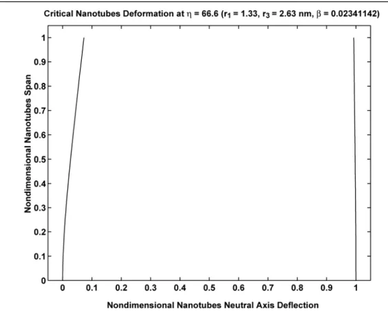
Fig. 8 The two neutral axes pull-in deflection of the nanotubes with different interior radii at η = 66.6.
1
r = 1.33 nm, r3 = 2.63 nm, t = 0.34 nm and D = 50 nm.
Fig. 10. SEM images of SiC particle (a) before and (b) after carbon nanotubes growth, and (c) enlarged SEM image of carbon nanotubes on SiC particle. (d) Dynamic fracture surface of 3% wt SiC/CNT specimen.
0.0 0.1 0.2 0.3 0.4 0.5 0.6 -50 0 50 100 150 200 250 300 350 400 450 Stress (MPa) Strain SHPB-3% wt SHPB-Epoxy Static-3% wt Static-Epoxy
Fig. 12. Typical static and dynamic compressive stress- strain curves of specimens with and without SiC/CNT reinforced.
0.10 0.15 0.20 0.25 0.30 0.35 5 10 15 20 25 St re ss (M Pa ) Strain SHPB Static
目 录
第一章 绪 论... 1 1.1 引 言... 1 1.2 碳纳米管的结构、性质和应用... 3 1.3 碳纳米管力学相关性质的研究现状... 6 1.3.1 碳纳米管的弹性模量... 6 1.3.2 碳纳米管在拉、压、弯、扭作用下的变形分析... 10 1.3.3 表面力作用下的碳纳米管变形分析... 14 1.4 本文主要工作... 16 参考文献... 18 第二章 碳纳米管自重作用下的稳定性分析... 22 2.1 碳纳米管的连续介质模型... 22 2.1.1 梁模型... 22 2.1.2 壳模型... 24 2.1.3 准连续介质模型... 25 2.2 碳纳米管在自重作用下的稳定性分析... 28 2.2.1 量纲分析... 28 2.2.2 弹性柱模型... 29 2.3.3 算例和分析... 31 2.3 本章小结... 34 参考文献... 35 第三章 碳纳米管在 NEMS 中的吸合力学行为分析... 38 3.1 碳纳米管在 NEMS 中的应用... 383.2 NEMS 结构中作用力分析 ... 39 3.2.1 van der Waals 力 ... 39 3.2.2 Casimir 力 ... 43 3.3 基于碳纳米管的纳米开关吸合力学分析 ... 43 3.3.1 力学模型 ... 44 3.3.2 Galerkin 方法 ... 47 3.3.3 计算结果分析 ... 48 3.4 本章小结 ... 54 参考文献... 55 第四章 一类微/纳尺度杂交强化复合材料的制备 ... 57 4.1 碳纳米管增强复合材料的制备研究进展 ... 57 4.2 碳纳米管的制备 ... 59 4.2.1 电弧放电法 ... 59 4.2.2 激光蒸发法 ... 60 4.2.3 化学气相沉积法 ... 61 4.3 SiC/CNT 结构的制备 ... 61 4.4 杂交增强复合材料的制备 ... 66 4.4.1 模具的准备 ... 66 4.4.2 复合材料的制备 ... 67 4.5 本章小结 ... 71 参考文献... 71 第五章 碳纳米管复合材料的实验和理论研究 ... 73 5.1 碳纳米管复合材料的有效弹性模量 ... 73 5.2 碳纳米管复合材料界面强度分析 ... 81 5.3 杂交复合材料的静态压缩实验研究 ... 82 5.4 杂交复合材料的动态压缩实验研究 ... 86
5.4.1 分离式 Hopkinson 压杆 ... 86 5.4.2 SHPB 实验... 88 5.5 实验结果与理论分析... 90 5.6 本章小结... 95 参考文献... 95 第六章 全文总结... 98 致 谢... 100 攻读博士学位期间发表的论文... 101 博士学位论文独创性声明... 102
符号说明
A 碳纳米管的横截面积 D 两根碳纳米管间的距离 E 杨氏模量 Evdw 范德华能量 I 截面惯性矩 cr l 碳纳米管的临界长度 L 碳纳米管的长度 1 N ,N 2 碳纳米管轴向力 P 集中载荷 q 单位长度碳纳米管的重量 1 r ,r2 第一根碳纳米管的内半径和外半径 3 r ,r 4 第二根碳纳米管的内半径和外半径 o R ,R i 碳纳米管的外半径和内半径 2 2 1 R =r r ,R3 =r r3 1,R4 =r r4 1 t 碳纳米管的半壁厚 T 两根碳纳米管轴线之间的距离 1 u ,u 2 碳纳米管的挠度 1 U ,U 2 碳纳米管的无量纲挠度 B U 弹性弯曲能 S U 弹性拉伸能v 泊松比 V 体积含量 w 碳纳米管的挠度 1 r T β = ρ 碳纳米管的密度 1 ρ ,ρ2 单位体积内的原子数
( )
ξ φi 悬臂梁的形函数 σ 范德华半径 max σ , 碳纳米管的屈服应力 c τ 界面剪切强度( )
7 2 4 1 2 2 AL E rT η=第一章
绪 论
1.1 引 言
纳米科学技术是80年代末期刚刚诞生并正在崛起的新科技,是一个多种学科交叉 汇合而出现的新学科。它的基本涵义是在纳米尺度(10-9~10-7 m)内认识,控制和操 作单个原子,分子或者超分子,创造具有新的功能和特性的材料,器件和系统。纳米 不仅是一个空间尺度上的概念,而且也是一种新的思维方式。 纳米科学技术的出现添补了人类对原子、分子和宏观物体之间的中间领域认识的 空白。在这个领域,材料和结构出现了许多既不同于宏观物体,也不同于原子,分子 尺度的奇异现象。原子、分子、分子团和组件在不需人主动介入而自动有序排列,具有 自 组 装 (Self Assembly ) 效 应 , 如 印 刷 诱 导 自 组 装 (Lithographically Induced
Self-Assembly,LISA)。因结构和组成尺寸达到纳米级,与光波波长、德布罗意波长 以及超导态的相干长度或透射深度相当或更小时,周期性边界条件破坏而呈现出异常 的物理、化学和生物特性的小尺寸效应,如对光的宽频带强吸收,蓝移现象等。随着 尺寸减小,位于表面的原子数目占相当大的比例,比表面急剧增大,导致纳米材料具 有极高的表面活性,而出现了特殊的表面和界面现象。当粒子尺寸减小到某一临界值 时,费米能级附近的电子能级由准连续态变为离散态或者能级变宽的现象,如宏观导 电的金属在纳米尺度时,在低温下会出现绝缘性。这些现象所表现出来的特性有着极 其广泛的潜在的应用,引发了人们对于纳米技术的无限遐想,也预示着一场新的技术 革命。世界各国都在纳米科学技术领域纷纷投入巨资。 根据研究对象和研究方法的不同,纳米科学技术包括三个方面的内容:纳米材料 研制,纳米器件和系统开发,纳米科学计算和模拟。 根据发展时间和发展进程,纳米科学技术产品可以分为4个阶段[1]: 1)第一阶段(~2001-):被动的纳米结构。这一阶段主要集中在纳米颗粒的分 散,纳米块体材料以及对纳米材料的检测和控制。 2)第二阶段(~2005-):主动的纳米结构。纳米晶体管,放大器,药物的目标 释放,化学传感器,纳米开关/纳米镊子等都出现在这个阶段。这个阶段的目标是制 造新奇的器件和器件系统,信息技术,现代生物科学,纳米技术,社会科学将被结合 在一起。 3)第三阶段(~2010-):3D纳米系统和纳米系统的系统。这个阶段的研究将集 中在用各种合成、集成技术制造不同种类的纳米结构,和超分子系统工程,包括纳米
尺度和多尺度的网络结构,人工组织,纳米机电系统,基于纳米器件的细胞目标治疗 等。 4)第四阶段(~2015-):各类分子纳米系统。这个阶段中,纳米系统的每个分 子具有特定结构,发挥不同的作用。分子作为一个器件,组合在一起成为具有新功能 的结构。研究将集中在分子和超分子系统设计的原子操作,单个分子的动力学,分子 机器,光与物体间的控制相互作用等。 在人们对材料的研究进程中,碳元素由于以单质和化合物广泛存在于自然界,排 在地球中元素丰度的第14位,而备受关注。1991年,日本NEC公司的科学家Iijima[2]
在高分辨率透射电镜 (High Resolution Transmission Electron Microscopy,HRTEM ) 下发现了碳纳米管。在碳纳米管发现前,碳纤维一直是一种非常重要的复合材料增强 纤维,最初应用在火箭、宇航及航空等尖端科学技术中,现在还广泛应用于体育器械、 纺织、化工机械及医学领域。比碳纤维性能还要优越的碳纳米管的发现立刻吸引了大 量的来自物理,化学,材料,力学等领域的学者投身其中,引起了碳纳米科学的飞速 发展,使该领域成为十多年来纳米材料研究的热点之一。有一段时间内,碳纳米管几 乎成了纳米材料的代名词。 图1-1 碳的同素异形体 Fig.1-1 Allotropes of carbon
碳纳米管是分子尺度的碳纤维,它和金刚石、石墨、富勒烯(C60)一样,是碳
一维,二维和三维存在形式。自然界中,金刚石、石墨都不可能完全以单质形式存在, 因为它们不封闭的结构使得它们即使内部无缺陷,也必然会在表面留下很多悬键,而 C60和碳纳米管则不同,如果结构无缺陷,它们构成的是一个封闭结构。这也是碳纳 米管惰性强的重要原因。
1.2 碳纳米管的结构、性质和应用
最简单的碳纳米管可以看作是一层石墨片层卷起形成的,称为单壁碳纳米管(Single walled carbon nanotube,SWCNT)。通常单壁碳纳米管的直径为0.7-10nm[3],
直径大于3 nm时,单壁碳纳米管就不稳定[4,5]。如果碳纳米管包含两层以上的石墨片
层,就称为多壁碳纳米管(Multi-walled carbon nanotube,MWCNT),片层之间的距 离为0.34~0.4 nm。 石墨片层的碳原子之间是SP2杂化,相互之间以碳-碳σ键结合起来,形成由六边 形组成的蜂窝状结构作为碳纳米管的骨架。每个碳原子有一个未成对的p电子位于垂 直与片层的 π 轨道上,相邻原子上未参与杂化的一对P电子π 轨道相互重叠形成跨越 整个碳纳米管的共轭π 电子云。电子可以在层内运动,而在层间阻力很大。 图1-2 石墨片层的键结构 Fig.1-2 Bond structures of a graphite layer
碳纳米管与石墨片层有点不同的是碳纳米管壁是弯曲的,形成空间拓扑结构,其
中有一部分产生SP3杂化。碳纳米管不总是笔直的,局部可能出现凹凸的现象,这是
由于在六边形结构中混杂了五边形和七边形。出现五边形的地方,由于张力的关系导 致碳纳米管向外凸出。如果五边形恰好出现在碳纳米管的顶端,就形成碳纳米管的封 口。出现七边形的地方碳纳米管则向内凹进。
a) 单壁碳纳米管束[6] b) 互相缠绕的多壁碳纳米管 图1-3 碳纳米管的存在形态
a) SWCNT bundle[6] b) Entangled MWCNTs Fig. 1-3 Existence of carbon nanotubes
碳纳米管的纳米尺寸使其具有很大的比表面积。碳纳米管的比表面积与壁厚有 关。壁厚越小,比表面积越高,所以单壁碳纳米管具有较大的比表面积。对于1~2 nm 的单壁碳纳米管,外比表面积之和可以达到8000 m2/g。比表面积大,管间的范德华 力作用的效果就强。碳纳米管的比表面积与其成束状况关系很大。随着碳纳米管层数 的增加,趋向于单根存在。通常多壁碳纳米管以互相缠绕形态存在,单壁碳纳米管多 成束存在,见图1-3。 图1-4 碳纳米管的手性 Fig.1-4 The chirality of SWCNT
(对称)和手性型(不对称)[3]。有两种非手性的碳纳米管:扶手型(Armchair)和 锯齿型(Zigzag)。 碳纳米管上原子排列的方向常用矢量Ch(n, m)表示,Ch也称作螺旋向量。 Ch = na1+ma2=(n,m) (1-1) 式中n,m是整数,且0≤ n ≤ m ;a1和a2分别表示两个基矢,它们的夹角为60°。 手性角定义为矢量Ch和a1之间的夹角,取值范围为0D ≤ θ ≤30D。锯齿型和扶手 型碳纳米管分别对应于θ =0D和θ =30D,即n≠0,m = 0和n=m。螺旋向量C h和基矢 a1与它们之间的夹角的关系由下式确定。 mn n m m n h h + + + = = 2 2 1 1 2 2 cos a C a C θ (1-2) 从碳纳米管的构造过程可以看出,螺旋向量Ch的数值是碳纳米管的管周长,所以 碳纳米管的直径为 2 2 h a m n mn d π π + + = C = (1-3) 与Ch垂直的矢量T叫平移向量,是沿碳纳米管轴向重复碳纳米管单胞的最短距 离,可以表示为 1 1 2 2 1 2 2 2 R R m n n m t t d d + + = + = + T a a a a (1-4) R d 是2m+n和2n+m的最大公约数。 设x为m,n的最大公约数,则 3 h/dR = T C (1-5) 其中 , 3 3 , 3 R x n m x d x n m x − ⎧ = ⎨ − ⎩ 不是 的整数倍 是 的整数倍 (1-6) 碳纳米管的导电性与其结构紧密相关,可能是导体,也可能是半导体,取决于管 的手性。通过对单壁碳纳米管电子能带结构的计算表明,当碳纳米管(n,m)满足 2n + m = 3q(q是整数)时,碳纳米管表现出金属性,为导体,否则就是半导体。与 石墨类似,碳纳米管层间的电阻比较大。有大约三分之二的单壁碳纳米管为半导体, 三分之一为导体。多壁碳纳米管则多为导体。由于碳纳米管大的长细比和高的导电性, 很低的含量(0.01%甚至0.004%)就可以达到渗透阀值[7]。 由于C=C键是自然界中最强的价键,因此碳纳米管具有极高的轴向强度,高于 任何已知的材料,其理论抗拉强度为钢的100倍,而密度仅为钢的1/6。碳纳米管具有
很大的长细比(>1000)。有美国科学家[8]在Si基底上制备出直径1.4 nm,长度4 cm的 单壁碳纳米管,长细比达到107。我们的理论计算表明[9],直立单壁碳纳米管在自重作 用下临界长细比可以达到106。 碳纳米管的中空结构,使得碳纳米管的密度比较低。一般来说,单壁碳纳米管的 密度约为1.33 g/cm3,而多壁碳纳米管的密度为1.6~1.7 g/cm3。由于碳纳米管的高强 度,低密度,大长细比使得其成为复合材料极好的增强纤维,甚至是太空升降机绳索 唯一可以选择的材料[10]。Zheng等人[11]在理论上预测出多壁碳纳米管的内管可以在外 管中以高达十亿赫兹的频率做往返运动。 由于碳纳米管独特的性质,使得其可以广泛地应用在纳米尺度的器件(如纳米镊 子[12-14],AFM扫描针尖[15],化学传感器[16],纳米秤[17]),制作纳米材料的模板[18], 复合材料的增强纤维[19],驻能驻气材料[20],场发射器[21]等。
1.3 碳纳米管力学相关性质的研究现状
随着碳纳米管的广泛应用,涉及到的力学问题也就越来越广泛,与任何其他材料 一样,自从碳纳米管被发现后,碳纳米管的弹性性质,如杨氏模量,泊松比,弯曲刚 度等就成为研究的热点。下面我们对碳纳米管力学相关性质的研究进展进行回顾。 1.3.1 碳纳米管的弹性模量 自从碳纳米管被发现起,大量工作集中在确定它的弹性模量上。对碳纳米管弹性 模量的研究主要分为实验观测,原子学模拟和连续介质力学模型研究。 最早用理论方法预测碳纳米管弹性模量的可能是Overney [22]。他用经验Keating Hamiltonian 方法研究了包含 100,200,400 个原子的(5,5)碳纳米管的结构刚度,后来 Treacy[23]等指出,Overney 的结果应该在 1.5 到 5.0 TPa。Lu[24]用经验力常数模
型(Force-constant model)系统地研究了碳纳米管的力学性质,他认为碳纳米管的弹 性模量对半径,手性和管壁数目不敏感,得到的碳纳米管的杨氏模量为约为1 TPa, 剪切模量约为0.5 TPa,泊松比约为 0.28。Hernandez 等人[25] 考虑了曲率效应,利用 非正交紧束缚方法研究了碳纳米管的弹性性质,认为杨氏模量对碳纳米管直径的依赖 性不大,约为 1.22~1.26 TPa。当直径增大时,杨氏模量也增大,接近于石墨片层的 极限值。 Robertson[26]等用Brenner 经验势和第一原理研究了半径小于 0.9 nm 的单壁碳纳 米管的能量和弹性性质。他们的结果表明应变能与 1/R2 有着一致的线性关系,这说
明小变形梁理论在小半径极限的情况下仍然有效。Gao[5]研究了半径比较大的单壁碳 纳米管,得到类似的应变能和 1/R2 的线性关系。用分子动力学模拟密排的单壁碳纳 米管,通过计算势能函数的二阶导数,得到杨氏模量值在640.30 GPa 和 673.49 GPa 之间。 近几年,分子力学模型被用来研究碳纳米管的弹性性质。最近的研究结果表明, 碳纳米管的弹性模量具有尺寸效应。 在这个模型中,碳纳米管整个系统的空间位能可以写为键的能量和非键能量的总 和。
∑
∑
∑
∑
∑
∑
+ + + + + = Ur U U U UvdW Ues U θ φ ω (1-7) 其中Ur是键的拉伸能量,Uθ是键角变化引起的能量,Uφ是二面角改变引起的能量, Uω是面外旋转引起的能量,UvdW 是范德华能,U 是静电势。 es Li[27]等用分子力学模型研究了单壁碳纳米管的弹性性质,出于小变形假设,他们 省略了静电力作用和范德华能,发现当直径小于1 nm 时,杨氏模量和剪切模量对管 径有很强的依赖性。随着直径减小,杨氏模量和剪切模量急剧减小。后来他们将最初 为单壁碳纳米管提出的分子结构力学方法拓展到研究多壁碳纳米管,考虑层间范德华 力作用,得到杨氏模量约为 1.05±0.05 TPa,比单壁碳纳米管略高,剪切模量为 0.40±0.05 TPa,比单壁碳纳米管略低。碳纳米管的手性,直径,层数对弹性性质的 影响虽然不大,但是很容易分辨出来。Chang[28]等也用分子力学模型来研究碳纳米管 的弹性性质,他们仅考虑了键角变化和键的伸长,得到杨氏模量为1.06 TPa,泊松比 为 0.16。Chang 所得杨氏模量的值以及变化趋势与 Li 的结果非常吻合。但是在直径 小于1 nm 时,锯齿型单壁碳纳米管的泊松比比扶手型的对直径更敏感。 Yakobson 等[29]用 Tersoff-Brenner 势函数模拟了单壁碳纳米管在轴向载荷作用下 响应,将模拟结果和连续壳模型进行比较,得到碳纳米管的杨氏模量为5.5 TPa,有 效厚度为0.066 nm。Zhou 等[30]根据电子能带理论估计了应变能和杨氏模量,在连续 介质弹性理论基础上拟合卷曲能,压缩或拉伸能和弯曲能,得到单壁碳纳米管的杨氏 模量为5.1 TPa,有效厚度为 0.071 nm。Vodenitcharova 等[31]用连续介质力学的环理论 来模拟单壁碳纳米管受到静水压力,得到杨氏模量为4.88 TPa,有效壁厚为 0.0617 nm。 Wang 等人[32]研究了YBB 的薄壳模型的尺寸依赖性。在直径小于 1.5 nm 时,碳 纳米管的杨氏模量,剪切模量,泊松比,壁厚都对直径很敏感。泊松比对手性极其敏 感,杨氏模量,剪切模量,壁厚等对手性则不敏感。 从前面的分析可以看出,对碳纳米管的弹性性质来讲,无论使用哪种分析方法,都是在直径小于1 或 1.5nm 才有明显的尺寸效应。到目前为止,明显的尺寸效应只有 在理论分析中才能发现。因为临界尺寸太小,所以目前通过实验来验证尺寸效应还有 困难。 除去人们在理论分析中的努力外,在实验中确定碳纳米管的弹性模量方面,人们 也做出了很多尝试。 图1-5 横向原子力显微镜测量碳纳米管力学性质的原理的示意图
Fig.1-5 Overview of one approach to probe mechanical properties of nanotubes and nanorods.
Treacy[23]等在TEM 中测量与时间有关的碳纳米管的热振动振幅,通过对 11 根碳
纳米管的杨氏模量的计算,得到电弧放电法制备的多壁碳纳米管的平均杨氏模量为
1.8 TPa,但数据比较分散,最大的达到 4 TPa,最小的只有 0.4 TPa。Krishnan 等[33]
做了一个单壁碳纳米管相似实验,得到 27 根单壁碳纳米管的平均杨氏模量为 1.3-0.4/+0.6TPa。Wong[34]等将碳纳米管分散在用普通光刻技术得到的基体上,然后利 用 AFM 探针将多壁碳纳米管慢慢压弯,测量原理如图 1-5。用悬臂梁位移等于 EI PL3/3 来计算得到的弹性模量。实验中测量了直径在26~76 nm 之间的多壁碳纳米 管,平均弹性模量为1.28±0.59 TPa。由于实验工程中碳纳米管受到 AFM 探针作用可 能发生扭转,因此会导致误差。Lourie 等人[35]用拉曼光谱测量了环氧树脂基体中碳纳 米管的压缩变形,得到单壁碳纳米管杨氏模量为 2.8~3.6 TPa,多壁碳纳米管杨氏模 量为1.7~2.4 TPa。Salvetat 等人[36]用AFM 探针压迫分散在抛光的氧化铝多孔膜上碳 纳米管管束。用两端固支梁的理论来计算碳纳米管的弹性模量,得到碳纳米管的杨氏 模量为 410 160 810+ − TPa。这种方法测得的剪切模量是单壁碳纳米管管束之间发生相对滑移 的强度,并不是本身的剪切模量,并且假设管束与模板之间没有滑动,因此结果有一 (b) 一端固支,一端自由梁的示 意图。梁长度 L,在 x=a 处承受 点 P,f为分布摩擦力。 (a) AFM 探针梁弯曲的示意图, 下面曲线表示横向力大小。
点偏差。Pan[37]等人用一种小样品拉伸机之间测量了宏观碳纳米管的弹性模量。他们
得到的杨氏模量为0.45±0.23 TPa,拉伸强度为 1.72±0.64 GPa。Yu 等[38]用两个AFM
探针组合,在SEM 中测量了单根多壁碳纳米管和单壁碳纳米管束的弹性模量。通过
计算得到最外层碳纳米管的拉伸强度为11~63 GPa,杨氏模量为 0.27~0.95 TPa。图
1-6 和图 1-7 给出了碳纳米管杨氏模量的理论和实验结果。
图1-6 碳纳米管杨氏模量的理论研究结果
Fig.1-6 Theoretical results of Young’s moduli of carbon nanotubes
图1-7 碳纳米管杨氏模量的实验结果
与轴向相比,碳纳米管径向力学行为研究的则比较少。Shen[39]等用扫描力显微镜
径向压缩一些约10 nm 的多壁碳纳米管,得到压缩强度大于 5.3 GPa,同时发现径向
压缩模量随着压力增大而增大,变形可达到46%。Yu[40]等用AFM 轻敲模式对单根碳
纳米管进行纳米压痕研究,观察到的变形特征与 Shen 等的观察结果类似。他们利用
Hertz 接触模型估计多壁碳纳米管的有效压痕模量值从 0.3 GPa 到 4 GPa。Palaci 等人
[41]研究了39 根具有同一外径/内径比(R ext/Rint=2.2±0.2)的多壁碳纳米管的纳米压痕, 也用Hertz 理论估计了径向模量。他们发现,碳纳米管的径向杨氏模量随着碳纳米管 外径的变大而迅速降低,最后趋近于30±10 GPa。 到目前为止,对碳纳米管的杨氏模量和有效壁厚还存在争议。从实验中得到的数 据分散性很大,原因是实验中使用的制备方法不同,得到的碳纳米管也不同,这些碳 纳米管中都不同程度的存在着缺陷。还有一个原因是因为实验方法和测量精度引起的 误差。用原子学模拟得到的数值的准确性,则取决于所选取势函数的准确性。实验得 到的数值与理论模拟得到的数据的差别在于,实验中使用碳纳米管都有不同程度的缺 陷,而理论分析中都认为碳纳米管是无缺陷的。现在多数研究人员在实际应用中采用 1 TPa 和 0.34 nm 作为碳纳米管的杨氏模量和壁厚。 1.3.2 碳纳米管在拉、压、弯、扭作用下的变形分析 碳纳米管在拉伸作用下的变形 图1-8 stone-wales 形变 Fig. 1-8 stone-wales transmission
究的重要工具。受到轴向拉伸的碳纳米管,在超出弹性形变后,碳纳米管呈现特殊的 塑性形变以消除应力,这种塑性变形成为Stone-Wales 形变。原来的 6-6-6-6 结构会变 成5-7-7-5,见图 1-8。 Yakobson 等人[42]基于 Tersoff-Brenner 势函数模拟了单壁碳纳米管在轴向拉伸作 用下的形貌和断裂过程。在判断碳纳米管断裂的临界点时,Yakobson 等人用了如下 判据:当一个或几个C—C 键几乎同时断裂并导致管壁产生“孔”时,断裂发生。他 们模拟单壁碳纳米管的断裂并得到了很有趣的结果(图 1-9):起初随着应力的增加, 在碳纳米管网格中出现Stone-Wales 变形,碳管出现了类似颈缩的现象,超过临界点 后,继续拉伸单壁碳纳米管,大量Stone-Wales 变形出现,且在大角度弯曲下的变形 出现了两断裂端有原子链相连的情况,随着进一步拉伸原子链只剩下了一条,但这条 原子链在很长时间内都不会断开。此外他们还模拟了双壁碳纳米管的断裂,得出了与 单壁碳纳米管断裂类似的情形。他们还发现碳纳米管的脆韧性依赖于自身的结构, 5-7-7-5 的滑移与手性有关。 图1-9 单壁碳纳米管在拉伸作用下的断裂过程 Fig.1-9 Fracture process of carbon naotube under tension
碳纳米管在压缩作用下的变形 由于实验操作单根碳纳米管的难度太大,目前碳纳米管在轴向压缩的变形行为研 究方法主要有分子动力学和有限元模拟。 Yakobson 等人[29]采用 Tersoff-Brenner 势的分子动力学,模拟了碳纳米管压缩下 的屈曲。在图1-10 中可以看到在加载过程中有 4 个失稳突跳形态。每次失稳突跳都 对应一次明显的形状变化。
(a) 与形状变化相对应,应变能显示 4 个奇异点; (b)ε1=0.05;(c)ε2=0.076;(d) ε3=0.09;(e) ε4=0.13。
图1-10 对长为 6 nm,直径 1 nm 的扶手型(7,7)的碳纳米管的分子动力学模拟 Fig.1-10 MD simulation of armchair carbon nanotube under axial compression
Buehler 等[43]用Tersoff 势模拟了单壁碳纳米管在压载作用下的 3 种变形方式,见 图1-11。当长细比比较小时,碳纳米管表现出一个圆柱壳的特征。提高长细比,当长 细比大于 20 时,碳纳米管在压缩载荷作用下,表现出一个 Euler 杆的屈曲形态。继 续提高长细比,一个类似线一样的变形形态。 (a) 类圆柱壳的屈曲;(b) 类杆的局部屈曲;(c) 类线的变形。 图1-11 不同长细比的单壁碳纳米管轴向压缩变形机理的示意图 (a) Shell-like buckling; (b) Rod-like local behavior; (c) Wire-like deformation.
碳纳米管在弯矩作用下的变形 Yakobson 等[29]模拟了弯矩作用下的单壁碳纳米管的弯曲变形,如图 1-12b 所示 (13, 0)的碳纳米管,长度 8 nm,直径 1.02 nm。应变能首先以 2 次方的形式增长, 当到达临界值时突然降低,认为此时碳纳米管发生了弹性屈曲,然后能量基本线性增 长。Wong[34]等人用AFM 对多壁碳纳米管弯曲响应进行测试时发现,当载荷较小时, 力和位移是线性关系,当载荷增加到某一临界值时,会突然降低,然后继续增长,但 刚度明显降低。Poncharal[17]等在机电激振多壁碳纳米管的在实验中发现,多壁碳纳米 管在受压一侧会出现波纹状的起皱现象,但同样的起皱现象在单壁碳纳米管不会出 现。对于直径较大的碳纳米管,它的弯曲刚度会从 1GPa 降低到 0.1 GPa。 (a)应变能曲线(实线)和力曲线(虚线);(b)屈曲后,形成的一个绞节点; (c-e)实验中观察到的多壁碳纳米管弯曲后形成的褶皱。 图1-12 碳纳米管的弯曲[29, 17] Fig. 1-12 Bending of carbon naotubes[29, 17]
碳纳米管在扭转作用下的变形
研究碳纳米管在扭转作用下变形的比较少。Yakobson 等人[29]模拟了一个 23 nm
长的锯齿型碳纳米管(13, 0)在扭转作用下的变形。变形能是扭转角度的一个函数。
整个碳纳米管的螺旋轴线不再是直线。当扭转角为8.6 时,碳纳米管就会缠绕在一起。 Arroyo 等人[44] 用准连续介质理论的薄膜模型研究了(10,10)碳纳米管的扭转变形, 见图1-10e。 (a) 能量/作用力和转角的关系;(b) 转角为 2.7;(c) 转角为 7.2; (d) 能量和转角的关系;(e)转角为 25°。 图1-13 碳纳米管的扭转变形 Fig.1-13 Twist of carbon nanotubes
1.3.3 表面力作用下的碳纳米管变形分析 虽然碳纳米管常被看作是圆柱形结构,然而这种结构并不一定总是稳定的。碳纳 米管在使用过程中,不可避免的要跟外界发生接触,在表面范德华力的作用下,碳纳 米管就会发生变形,因此对这个问题的研究就显得非常重要。 Ruoff[45]等首次研究了相邻两根碳纳米管之间的径向变形(图1-14)。在 TEM 图 片中可以看到两根碳纳米管相邻平面由于范德华力的作用产生的局部扁平形态。A, B 两根碳纳米管的内外部分的平均层间距分别差 0.07 nm 和 0.08 nm,这个差别就是 接触区域范德华力引起的压缩所致。
左边:两个相邻碳纳米管A 和 B 的 HRTEM 图像;右边:(a) 两双层个碳纳米管在范德华力作用 下的变形计算结果,(b) 对应于(a)的原子密度。在接触区域投影原子密度非常高,说明有变形产
生,(c) 两相邻的单壁碳纳米管变形的计算结果。 图1-14 碳纳米管在范德华力作用下的变形[45]
Fig.1-14 Deformation of carbon nanotube under surface forces [45]
a) 径向变形分别为 0%,2%,13%和 42%; b) 径向变形分别为 42%,25%,5%,<1%。 图1-15 碳纳米管径向变形的分子力学模拟结果[46]
Hertel[46]等用分子力学计算了单壁和多壁碳纳米管在基底上的吸附变形(图 1-15),发现碳纳米管的径向变形与管径,层数都有关系,管的径向和轴向变形将会 导致高能量的结合。随着管径增大,横截面的变形也迅速增大,但随着管壁的增加, 碳纳米管的刚度增加,变形就随之减小。
Gao[5]用分子动力学对单壁碳纳米管的圆形截面和塌陷截面两种构型的稳定性进
行了分析。通过对能量的对比找到两个临界半径Rmin和Rmax。对于R<Rmin的碳纳米
管,可以保持稳定的圆形截面;对于Rmin < <R Rmax的碳纳米管,圆形截面和塌陷截
面都可能存在;对于R>Rmax的碳纳米管,则只能以塌陷截面的形式存在,这是一个
自塌陷问题。这里得到的临界半径Rmin和Rmax分别约等于1.1 nm和3 nm,它们对碳纳
米管的手性不敏感。Gao等的研究对象是一根独立的单壁碳纳米管,Yu等证明当碳纳
米管与表面接触时, 由于表面力的存在会促进塌陷,所以需要进行修正。
Pantano[47]和Tang[48]都对自塌陷做了进一步的研究。Pantano用基于连续介质壳理
论的有限元模型对此进行了分析,得到了类似的结果。他的有限元模型不仅可以用来
模拟单壁碳纳米管,也可以模拟多壁碳纳米管。Tang等人给出了临界半径Rmin和Rmax
与两个长度d 和0 D W/ flat 之间的解析关系,其中d 是两平行石墨片层的平衡距离,0 flat W 是分离两个平行石墨片层单位面积上所需要的功,D是碳纳米管的有效弯曲刚 度。Tang等人得到的两个临界半径都小于Gao等人[5]的研究结果。
1.4 本文主要工作
NEMS和复合材料是碳纳米管应用的两个主要领域,本文针对碳纳米管在这两个 领域的应用开展研究工作。虽然有大量实验研究和理论工作针对碳纳米管的力学性质 展开,但对于NEMS系统中碳纳米管结构极限设计的研究却很少。NEMS中的纳米开 关/镊子是碳纳米管一个非常重要的应用方向。此类结构的极限设计是一个值得关注 的内容。由于纳米开关/镊子的结构和尺度,在表面力作用下,满足一定条件碳纳米 管臂就会发生吸合。对于这个问题,Dequesnes[49]等人用单自由度模型,研究了在范 德华力和静电力作用下,悬臂碳纳米管与基底的吸合行为。显然单自由度模型并不能 反应系统的真实情况,因此用连续模型来研究是非常必要的。另外碳纳米管的临界长 度也是结构设计关心的一个参数。对于碳纳米管复合材料,虽然有很多人在研究,但 到目前为止没有很成功的实践,碳纳米管的分散和对齐,界面强度,制备成本仍然制约着它的应用。 在碳纳米管应用中,单根碳纳米管的性能取着决定性的作用,从前面的分析中可 以看到,目前在这方面还有大量的工作要做,因此对单根碳纳米管的力学性能研究仍 然十分重要。关于碳纳米管在NEMS结构中应用的力学性质研究进展我们在第三章给 予介绍。复合材料作为碳纳米管一个非常重要的应用,离大规模应用也还有很长的路 要走。碳纳米管在复合材料应用中的力学问题,我们放在第五章中进行介绍。本文将 碳纳米管在NEMS结构和复合材料应用中的力学问题作为研究的重点。 本文主要内容分为以下几个部分: 1)用连续介质力学的柱(梁)理论研究单壁碳纳米管在自重作用下稳定性进行分 析。通过使用量纲分析,找到两个控制碳纳米管长细比lcr/R 的无量纲数ρgR E/ 和 / t R,系统研究了lcr/R 与无量纲数ρgR E/ 和t R/ 的关系。通过理论分析发现碳纳米 管在自重作用下的临界长细比lcr/R 高达106。采用碳纳米管几何尺寸的实验数据和两 种理论碳纳米管强度值,进行了几个实例分析。 2)将碳纳米管-碳纳米管纳米开关结构看作双悬臂梁结构,利用大变形理论建 立了范德华力作用下具有此类结构的吸合非线性方程,并用Galerkin方法对方程组进 行了数值求解。通过分析碳纳米管轴线挠度的斜率来确定吸合点,对碳纳米管间的距 离,内径,吸合长度等进行了详细分析,为基于碳纳米管的NEMS结构设计提供参考 和指导。 3)用流动化学气相沉积法在平均直径4微米的SiC颗粒上制备了多壁碳纳米管, 通过机械搅拌,将不同含量的SiC/CNT与环氧树脂混合,通过抽真空,注入模具,室 温固化,高温固化,切割等步骤,做成了微米/纳米杂交强化的复合材料。 4)利用制备好的杂交强化复合材料圆柱形试件,在MTS810试验机上进行了准静 态压缩实验,得到了不同体积含量的材料压缩强度和弹性模量,同时研究了真空度对 复合材料强度的影响。 5)以10 m/s的速度,用分离式Hopkinson压杆对杂交强化复合材料试件进行了动 态压缩实验。将动态实验结果与静态实验结果进行了比较,发现由于SiC/CNT杂交强 化作用,动态屈服强度的提高大于静态屈服强度的提高。 6)用SEM对动静态压缩实验后的试件破坏界面进行了观察,发现由于有SiC颗粒 做载体,没有发生通常碳纳米管增强复合材料中常见的碳纳米管团聚现象。电镜观察 还发现碳纳米管与碳化硅颗粒之间的连接强度比较弱。
参考文献
[1] Roco M C. Nanoscale science and engineering: unifiying and transforming tools. American Institute of Chemical Engineers Journal, 2004, 50(5): 890-897.
[2] Iijima S. Helical Microtubules of Graphitic Carbon. Nature, 1991, 354: 56-58.
[3] Saito R, Dresselhaus G and Dresselhaus M S. Physical properties of carbon nanotubes. London: Imperial college press, 1998.
[4] Hertel T, Walkup R E, Avouris P. Deformation of carbon nanotubes by surface van der Waals forces. Physical Review B, 1998,58:13870-13873.
[5] Gao G H, Cagin T and Goddard W A. Energetics, structure, mechanical and vibrational properties of single-walled carbon nanotubes. Nanotechnology, 1998, 9:184-191.
[6] Thess A, Lee R, Nikolaev P, et al. Crystalline ropes of metallic carbon nanotubes. Science, 1996, 273: 483-487.
[7] Sandler J K W, Kirk J E, Kinloch I A, et al. Ultra-low electrical percolation threshold in carbon-nanotube-epoxy composites. Polymer, 2003 44: 5893.
[8] Zheng L X, O’Connell M J, Doorn S K, et al. Ultralong single-wall carbon nanotubes. Nature Materials, 2004, 3: 673–676.
[9] Wang G W, Zhao Y P, Yang G T. The stability of a vertical single-walled carbon nanotube under its own weight. Materials & Design, 2004, 25(6): 453-457.
[10] Edward B C. Design and deployment of a space elevator. Acta Astronautica, 2000, 47(10): 735-744.
[11] Zheng Q S and Jiang Q. Multiwalled carbon nanotubes as gigahertz oscillators. Physical Review Letters, 2002, 88: 045503.
[12] Kim P and Lieber C M. Nanotube nanotweezers. Science, 1999, 286: 2148-2150
[13] Akita S, Nakayama Y, and Mizooka S, et al. Nanotweezers consisting of carbon nanotubes operating in an atomic force microscope. Applied Physics Letters, 2001, 79: 1691-1693.
[14] Jang J E, Cha S N and Choi Y, et al. Nanoelectromechanical switches with vertically aligned carbon nanotubes Applied Physics Letters, 2005, 87: 163114-3.
[15] Dai H J, Hafner J H, Rinzler A G, et al. Nanotubes as nanoprobes in scanning probe microscopy. Nature, 1996, 384:147-150.
[16] Kong J, Franklin N R and Zhou C. Nanotube molecular wires as chemical sensors. Science, 2000, 287: 622-625.
[17] Poncharal P, Wang Z L, Ugarte D, et al. Electrostatic deflections and electromechanical resonances of carbon nanotubes. Science, 1999, 283:1513-1516. [18] Ajayan P M, Iijima S. Capillarity-induced filling of carbon nanotubes. Nature, 1993,
361:333 - 334.
[19] Ajayan P M, Stephan O, Colliex C et al. Aligned carbon nanotube arrays formed by cutting a polymer resin-nanotube composite. Science, 1994, 265: 1212-1214
[20] Chen P, Wu X, Lin J et al. High H2 Uptake by alkali-doped carbon nanotubes under
ambient pressure and moderate temperatures. Science, 1999, 285:91-93.
[21] de Heer W A, Châtelain A, Ugarte D. A carbon nanotube field-emission electron source. Science, 1995, 270:1179-1180.
[22] Overney G, Zhong W, and Tomanek D. Structural rigidity and low-frequency vibrational-modes of long carbon tubules, Zeitschrift für Physik D Atoms, Molecules and Clusters, 1993, 27:93–96.
[23] Treacy, M.M., Ebbesen, T.W., Gibson, J.M. Exceptionally high Young’s modulus observed for individual carbon nanotubes. Nature, 1996, 38: 678.
[24] Lu J P. Elastic properties of carbon nanotubes and nanoropes. Physics Review Letters, 1997, 79:1297-1300.
[25] Hernandez E, Goze C, Bernier P, et al. Elastic Properties of Single-wall Nanotubes. Applied Physics A, 1999, 26 :287-292.
[26] Robertson DH, Brenner DW, and Mintmire JW. Energetics of nanoscale graphitic tubules, Physical Review B, 1992, 45:12592–12595.
[27] Li C, Chou TW. A structural mechanics approach for the analysis of carbon nanotubes. International Journal of Solids Structure, 2003, 40(10):2487–2499.
[28] Chang T and Gao H. Size-dependent elastic properties of a single-walled carbon nanotube via a molecular mechanics model. Journal of the mechanics and physics of solids, 2003, 51:1059-1074.
[29] Yakobson B I, Brabec C J and Bernholc J. Nanomechanics of carbon tubes: Instability beyond linear response. Physical Review Letters, 1996, 76: 2511-2514.
[30] Zhou X, Zhou J J and Ou-Yang Z C. Strain energy and Young’s modulus of single-wall carbon nanotubes calculated from electronic energy-band theory. Physics Review B, 2000, 62: 13692-6.
[31] Vodenitcharova T, Zhang LC. Effective wall thickness of a single-walled carbon nanotube. Physical Review B, 2003, 68(16): 165401.
[32] Wang L, Zheng Q, Liu J Z et al. Size dependence of the thin-shell model for carbon nanotubes. Physical Review Letters, 2005,95:105501.
[33] Krishnan A, Dujardin E, Ebbesen T W, et al. Young’s modulus of single-walled nanotubes. Physical Review B, 1998, 58: 14013–14019.
[34] Wong E W, Sheehan P E and Lieber C M. Nanobeam mechanics: elasticity, strength, and toughness of nanorods and nanotubes. Science, 1997, 277: 1971-1975.
[35] Lourie O, Cox D M, and Wagner H D. Buckling and collapse of embedded carbon nanotubes, Physical Review Letters, 1998, 81:1638–1641.
[36] Salvetat J P, Kulik A J, Bonard J M et al. Elastic modulus of ordered and disordered multiwalled carbon nanotubes. Advanced Materials, 1999, 11:161–165.
[37] Pan ZW, Xie SS, Lu L et al. Tensile tests of ropes of very long aligned multiwall carbon nanotubes, Applied Physical Letters, 1999, 74:3152–3154.
[38] Yu MF, Files BS, Arepalli S et al. Tensile loading of ropes of single wall carbon nanotubes and their mechanical properties. Physical Review Letters, 2000, 84: 5552–5555
[39] Shen W, Jiang B, Han B S et al. Investigation of the radial compression of carbon nanotubes with a scanning probe microscope. Physical Review Letters, 2000, 84(16):3634-3637
[40] Yu M F, Kowalewski T, Ruof R S.Investigation of the radial deformability of individual carbon nanotubes under controlled indentation force. Physical Review Letters, 2000, 85(7) : 1456-1459
[41] Palaci I, Fedrigo S, Brune H, et al. Radial elasticity of multiwalled carbon nanotubes. Physical Review Letters, 2005, 94(17):175502.
[42] Yakobson B I, Campbell M P, Brabec C J, et al. High strain rate fracture, and C-chain. unraveling in carbon nanotubes. Computational Material Science, 1997, 8: 341-348 [43] Buehler M J, Kong Y and Gao H. Deformation mechanisms of very long single-wall
carbon nanotubes subject to compressive loading. Journal of Engineering Materials and Technology, 2004, 126:245-249.
[44] Arroyo M and Belytschko T. An atomistic-based finite deformation membrane for single layer crystalline films. Journal of the Mechanics and Physics of Solids, 2002, 50 :1941-1977.
[45] Ruoff R S, Tersoff J, Lorents D C, et a1. Radial deformation of carbon nanotubes by van der Waals forces. Nature (London), 1993, 364(6437):514-516.
[46] Hertel T, Walkup RE, and Avouris P. Deformation of carbon nanotubes by surface van der Waals forces, Physical Review B, 1998, 58:13870-13873.
[47] Pantano A, Parkes D M and Boyce M C. Mechanics of deformation of single- and multi-wall carbon nanotubes. Journal of the mechanics and physics of solids, 2004, 52:789-821.
[48] Tang T, Jagota A, Hui C Y, et al. Collapse of single-walled carbon nanotubes. Journal of Applied Physics, 2005, 97:074310.
[49] Dequesnes M, Rotkin S V and Aluru N R. Calculation of pull-in voltages for carbon-nanotube-based nanoelectromechanical switches. Nanotechnology, 2002, 13: 120-131.


![Fig. 1-12 Bending of carbon naotubes [29, 17]](https://thumb-eu.123doks.com/thumbv2/123doknet/14697667.746456/41.892.180.772.533.777/fig-bending-of-carbon-naotubes.webp)