HAL Id: tel-03082647
https://tel.archives-ouvertes.fr/tel-03082647
Submitted on 18 Dec 2020
HAL is a multi-disciplinary open access
archive for the deposit and dissemination of
sci-entific research documents, whether they are
pub-lished or not. The documents may come from
teaching and research institutions in France or
abroad, or from public or private research centers.
L’archive ouverte pluridisciplinaire HAL, est
destinée au dépôt et à la diffusion de documents
scientifiques de niveau recherche, publiés ou non,
émanant des établissements d’enseignement et de
recherche français ou étrangers, des laboratoires
publics ou privés.
Automotive embedded software design using formal
methods
Vassil Todorov
To cite this version:
Vassil Todorov. Automotive embedded software design using formal methods. Modeling and
Simula-tion. Université Paris-Saclay, 2020. English. �NNT : 2020UPASG026�. �tel-03082647�
Thè
se de
doctorat
NNT : 2020UP ASG026Automotive embedded software
design using formal methods
Thèse de doctorat de l’Université Paris-Saclay
École doctorale n◦580, Sciences et Technologies de l’Information et de la Communication
Spécialité de doctorat: Informatique Unité de recherche: Université Paris-Saclay, CNRS, Laboratoire de recherche en informatique, 91405, Orsay, France Référent: CentraleSupélec
Thèse présentée et soutenue à Gif-sur-Yvette, le 9 décembre 2020, par
Vassil TODOROV
Composition du jury:
Pascale Le Gall Présidente et examinatrice Professeur, CentraleSupélec
Gérard Berry Rapporteur et examinateur Professeur émérite, Collège de France
Cesare Tinelli Rapporteur et examinateur Professeur, University of Iowa
Sylvie Putot Examinatrice
Professeur, Ecole Polytechnique
Fabrice Kordon Examinateur
Professeur, Sorbonne Université
Sylvain Conchon Examinateur
Professeur, Université Paris-Saclay
Frédéric Boulanger Directeur de thèse Professeur, CentraleSupélec
Safouan Taha Co-encadrant de thèse
VASSIL TODOROV
AUTOMOTIVE EMBEDDED SOFTWARE DESIGN USING FORMAL METHODS
Automotive Embedded
Software Design Using
Formal Methods
Vassil Todorov
PhD thesis defended on December 9
th, 2020
Gérard Berry
Cesare Tinelli
Sylvie Putot
Pascale Le Gall
Fabrice Kordon
Sylvain Conchon
Frédéric Boulanger
Safouan Taha
Armando Hernandez
Professor Emeritus at Collège de France
Professor at University of Iowa
Professor at Ecole Polytechnique
Professor at CentraleSupélec
Professor at Sorbonne Université
Professor at Université Paris-Saclay
Professor at CentraleSupélec
Associate Professor at CentraleSupélec
Senior software expert at Groupe PSA
(assert (not (=> (and (= FlipFlopReset~0.L3$0 (>= Timer~0.L5$0 2400)) $PropDecelerationHigh$0 (>= AtLeastNTicks~0.L5$0 0)
(>= Timer~0.L5$0 AtLeastNTicks~0.L5$0) (=> FlipFlopReset~0.L3$0 true)
(=> false FlipFlopReset~0.L3$0))
(and (= FlipFlopReset~0.L3$1 (>= Timer~0.L5$1 2400)) $PropDecelerationHigh$1 (>= AtLeastNTicks~0.L5$1 0) (>= Timer~0.L5$1 AtLeastNTicks~0.L5$1) (=> FlipFlopReset~0.L3$1 true) (=> false FlipFlopReset~0.L3$1))))) (check-sat) (echo "@DONE") ; Yices2: sat ; Yices2: @DONE (get-model) (echo "@DONE")
A U T O M O T I V E E M B E D D E D S O F T WA R E D E S I G N
U S I N G F O R M A L M E T H O D S
D O C T O R A L T H E S I S
Vassil Todorov
A thesis submitted in fulfillment of the requirements
for the degree of
Doctor of Philosophy in Computer Science
Committee in charge
Pr. Gérard Berry (Collège de France) Reviewer Pr. Cesare Tinelli (University of Iowa, USA) Reviewer Pr. Sylvie Putot (Ecole Polytechnique, France) Examiner Pr. Pascale Le Gall (CentraleSupélec, France) Examiner Pr. Fabrice Kordon (Sorbonne Université, France) Examiner Pr. Sylvain Conchon (Université Paris-Saclay, France) Examiner Pr. Frédéric Boulanger (CentraleSupélec, France) Thesis advisor Ass. Pr. Safouan Taha (CentraleSupélec, France) Thesis co-advisor Armando Hernandez (Groupe PSA, France) Industrial tutor
This document was typeset using LATEX and inspired from the typographical
style classicthesis by André Miede and Ivo Pletikosi´c, and the nice book style adaptation by Hai Nguyen Van.
Vassil Todorov: Automotive embedded software design using formal methods, Doctoral Thesis, © December 2020
Dedicated to the loving memory of my dear aunt Prof. Magdalina Todorova
A B S T R A C T
The growing share of driver assistance functions, their criticality, as well as the prospect of certification of these functions, make their verification and vali-dation necessary with a level of requirement that testing alone cannot ensure.
For several years now, other industries such as aeronautics and railways have been subject to equivalent contexts. To respond to certain constraints, they have locally implemented formal methods. We are interested in the motivations and criteria that led to the use of formal methods in these industries in order to transpose them to automotive scenarios and identify the potential scope of application.
In this thesis, we present our case studies and propose methodologies for the use of formal methods by non-expert engineers. Inductive model checking for a model-driven development process, abstract interpretation to demonstrate the absence of run-time errors in the code and deductive proof for critical library functions.
Finally, we propose new algorithms to solve the problems identified during our experiments. These are, firstly, an invariant generator and a method using the semantics of data to process properties involving long-running timers in an efficient way, and secondly, an efficient algorithm to measure the coverage of the model by the properties using mutation techniques.
R É S U M É
La part croissante des fonctions d’assistance à la conduite, leur criticité, ainsi que la perspective d’une certification de ces fonctions, rendent nécessaire leur vérification et leur validation avec un niveau d’exigence que le test seul ne peut assurer.
Depuis quelques années déjà d’autres domaines comme l’aéronautique ou le ferroviaire sont soumis à des contextes équivalents. Pour répondre à certaines contraintes ils ont localement mis en place des méthodes formelles. Nous nous intéressons aux motivations et aux critères qui ont conduit à l’utilisation des méthodes formelles dans ces domaines afin de les transposer sur des scénarios automobiles et identifier le périmètre potentiel d’application.
Dans cette thèse, nous présentons nos études de cas et proposons des métho-dologies pour l’usage de méthodes formelles par des ingénieurs non-experts. Le model checking inductif pour un processus de développement utilisant des modèles, l’interprétation abstraite pour démontrer l’absence d’erreurs d’exé-cution du code et la preuve déductive pour des cas de fonctions critiques de librairie.
Enfin, nous proposons de nouveaux algorithmes pour résoudre les problèmes identifiés lors de nos expérimentations. Il s’agit d’une part d’un générateur d’invariants et d’une méthode utilisant la sémantique des données pour traiter efficacement des propriétés comportant du temps long, et d’autre part d’un al-gorithme efficace pour mesurer la couverture du modèle par les propriétés en utilisant des techniques de mutation.
Р е з ю м е Нарастващият дял на функциите за помощ на водача, тяхната критичност, както и перспективите за сертифицирането им, правят тяхната проверка и валидиране на ниво, на което само тестването не е достатъчно. От няколко години насам други области, като аеронавтиката и железо-пътният транспорт, се намират в подобен контекст. Ние се интересуваме от мотивациите и критериите, довели до използването на формални методи в тези области и как те биха могли да се приложат в автомобилна среда. В тази теза представяме нашите изследвания и предлагаме методологии за тяхното използване от инженери, които не са специалисти по формални методи. Индуктивна проверка на модели за процес на разработка използващ модели, статичен анализ базиран на абстрактна интерпретация, за да се де-монстрира липсата на грешки при изпълнение на код и дедуктивен анализ за критични библиотечни функции. А накрая, предлагаме нови алгоритми за решаване на проблемите, иден-тифицирани по време на нашите експерименти. Става въпрос от една страна за генератор на инварианти и метод, използващ семантиката на данните за ефективна обработка на свойства, включващи времеви таймери, и от друга страна за ефективен алгоритъм за измерване на покритието на модел по свойства, използвайки мутационни техники. xi
C O N T E N T S
1 i n t r o d u c t i o n 1
1.1 The Car – a Software-driven Electronic Device . . . 1
1.2 Problem . . . 2 1.3 Research Objectives . . . 3 1.4 Contributions . . . 3 1.5 Plan . . . 4 2 au t o m o t i v e s o f t wa r e d e s i g n a n d d e v e l o p m e n t 5 2.1 The V-Model . . . 6 2.2 Requirements Engineering . . . 7 2.2.1 Requirement Types . . . 7 2.3 Software Architecture . . . 8 2.3.1 AUTOSAR . . . 9
2.3.2 AUTOSAR and Software Verification . . . 10
2.4 Model-Based Design vs Manual Coding . . . 10
2.4.1 Traditional Manual Coding . . . 10
2.4.2 Model-Based Design . . . 11
2.5 Towards the Autonomous car . . . 12
2.6 Proving the Safety of the Autonomous Vehicle . . . 14
2.7 Conclusions . . . 17
i f o r m a l m e t h o d s a n d c e r t i f i c at i o n s ta n d a r d s 19 3 s a f e t y s ta n d a r d s a n d c e r t i f i c at i o n 21 3.1 Safety Standards . . . 21
3.1.1 Why do we Need Standards? . . . 21
3.1.2 Goal- and Prescription-Based Standards . . . 22
3.1.3 Functional Safety and IEC 61508 Derivated Standards . . 22
3.1.4 Railway – IEC 62279 / EN 5012x . . . 23
3.1.5 Medical – IEC 62304 . . . 24
3.1.6 Aviation – DO-178C . . . 24
3.1.7 Automotive – ISO 26262 . . . 25
3.2 Certification and Qualification . . . 25
3.3 Conclusions . . . 26
4 f o r m a l m e t h o d s – from theory to practice 27 4.1 Formal Methods and Tools – A Brief Introduction . . . 28
4.1.1 Abstract Interpretation . . . 28
4.1.2 Model Checking . . . 31
4.1.3 Deductive Methods . . . 39
4.1.4 Combining Program Verification Methods . . . 41
4.2 Industrial Applications of Formal Methods . . . 41
xiv c o n t e n t s
4.2.1 Formal Methods Comparison . . . 42
4.2.2 Abstract Interpretation Applications . . . 43
4.2.3 Model Checking Applications . . . 45
4.2.4 Deductive Proof Applications . . . 48
4.2.5 Interactive Proof Applications . . . 49
4.3 Formal Methods and Certification . . . 49
4.4 Challenges for the Application of Formal Methods . . . 50
4.5 Conclusions . . . 50
ii au t o m o t i v e s o f t wa r e d e s i g n u s i n g f o r m a l m e t h o d s 51 5 m e t h o d o l o g i e s f o r u s i n g f o r m a l m e t h o d s i n a n au t o m o -t i v e c o n -t e x -t 53 5.1 Related Work . . . 53
5.2 Methodology for Model-Based Design . . . 55
5.2.1 Motivation and Objectives . . . 55
5.2.2 High and Low-Level Requirements . . . 56
5.2.3 Guidelines for Writing Good Formal Properties . . . 56
5.2.4 Synchronous Observers . . . 57
5.2.5 Libraries and Imported Functions . . . 58
5.2.6 Workflow . . . 59
5.2.7 Run-time Errors Check . . . 60
5.2.8 Proving Non-regression . . . 60
5.2.9 Strategies . . . 60
5.2.10 Limitations . . . 60
5.2.11 Experiments . . . 61
5.3 Methodology for Sound Static Analysis . . . 63
5.3.1 Component-Level Analysis . . . 63
5.3.2 Complete System Analysis . . . 64
5.3.3 Hints for Reducing False Alarms . . . 64
5.4 Conclusions . . . 65
6 i n va r i a n t g e n e r at i o n f o r m o d e l c h e c k i n g o f t i m e p r o p -e r t i -e s 67 6.1 Use Case Presentation . . . 67
6.1.1 Model and Environment . . . 67
6.1.2 Writing Formal Properties . . . 69
6.1.3 Compositional Approach . . . 71
6.1.4 Results Analysis . . . 72
6.2 Approach and Contribution . . . 74
6.2.1 SCADE to Lustre Transformation . . . 74
6.2.2 Understanding the Problem . . . 74
6.2.3 Contribution . . . 75
6.3 Results and Benchmarks . . . 78
6.3.1 Our Use Cases . . . 78
c o n t e n t s xv
6.3.3 Kind Benchmark . . . 79
6.3.4 Collins Aerospace Use Cases . . . 80
6.4 Conclusions . . . 80
7 c ov e r a g e m e a s u r e b a s e d o n m u tat i o n a n d m o d e l c h e c k i n g 83 7.1 Preliminaries . . . 84
7.1.1 The JKind Model Checker . . . 84
7.1.2 IVC Formalizations . . . 86
7.2 Model Coverage Techniques . . . 88
7.2.1 Simple Running Example . . . 89
7.2.2 Slicing . . . 89
7.2.3 Inductive Validity Cores . . . 90
7.2.4 A Simple Mutator forMust-Cov: Equation remover . . . . 90
7.2.5 Using Other Mutators for Deep Coverage . . . 90
7.3 From Mutation testing to Mutation proof . . . 92
7.3.1 Mutators . . . 92
7.3.2 Our Contribution: Mutation Proof Algorithm . . . 93
7.4 Implementation and Initial Results . . . 95
7.4.1 Implementation . . . 95
7.4.2 Optimizations . . . 95
7.4.3 Initial Results . . . 96
7.4.4 Industrial Use Case Results . . . 97
7.5 Conclusions . . . 97
8 d e d u c t i v e p r o o f a p p l i e d t o a d i s c r e t e-valued function 99 8.1 Environment . . . 100
8.2 Experiment . . . 100
8.3 Results . . . 103
8.3.1 From Frama-C to the SMT solver . . . 103
8.3.2 The Difficult Goal . . . 104
8.3.3 Direct Proof with SMT-LIB . . . 104
8.3.4 Experience with the Why3 SMT Output Files . . . 104
8.3.5 Abstract Interpretation Combined with Deductive Proof . 105 8.4 Methodology . . . 105
8.5 Related Work . . . 105
8.6 Conclusions . . . 107
9 c o n c l u s i o n a n d p e r s p e c t i v e s 109 9.1 Research Objectives Fulfillment . . . 109
9.1.1 Research Objective 1: Industrial Applications of Formal Methods . . . 109
9.1.2 Research Objective 2: Experimental Application on Auto-motive Use Cases . . . 110
9.1.3 Research Objective 3: Methodologies . . . 111
9.2 Concrete Productions . . . 111
xvi c o n t e n t s
p u b l i c at i o n s 113
b i b l i o g r a p h y 115
l i s t o f f i g u r e s, tables and listings 135
l i s t o f d e f i n i t i o n s a n d t h e o r e m s 139
l i s t o f a c r o n y m s 141
a c k n o w l e d g m e n t s 145
1
I N T R O D U C T I O N
Computing is fundamentally invisible. When your tires are flat, you look at your tires, they are flat. When your software is broken, you look at your software, you see nothing.
— Gérard Berry A few years ago, the idea of cars driving themselves on our streets seemed unbelievable. However, the rapid advances in machine learning in recent years make us think that one day it could become reality. Today, trained machine learning algorithms are capable of driving cars in most of the common situa-tions. Most of the time, the decisions taken by those algorithms are good but sometimes they can be wrong, which could cause fatalities. The problem is that when they are wrong, nobody can explain why and fix the problem. We can just train them more and hope/pray that next time there will be fewer errors. Furthermore, machine learning algorithms could not be certified in the sense of a critical system because there is no specification against which an implementa-tion could be verified. As autonomous vehicles can be considered safety-critical systems similar to trains and airplanes, it is expected that authorities require their certification in the future.
In order to ensure the safety of the system and provide safety arguments for the certification authority, we cannot use only machine learning algorithms. The decisions taken by the machine learning algorithms should be supervised by more classical algorithms based on domain expert knowledge. These non-machine learning supervision algorithms will be the safety-critical part of the software and could then be certified.
1.1 t h e c a r – a software-driven electronic device
In the 20thcentury automobile, the engine was the core technology. Two main
periods can be distinguished for the engine control: mechanical control before the 70-80s and electronic control after. The electronic fuel control injection sys-tem offered a better fuel dosage and reduced the fuel consumption compared to the previous carburetor-based mechanical injection system.
In the 21st century automobile, we observe a transition from a hardware-driven machine to a software-hardware-driven electronic device. Today, software, large
2 i n t r o d u c t i o n
computing power, and advanced sensors enable most modern innovations, from efficiency to connectivity to electrification to autonomous driving and new mo-bility solutions.
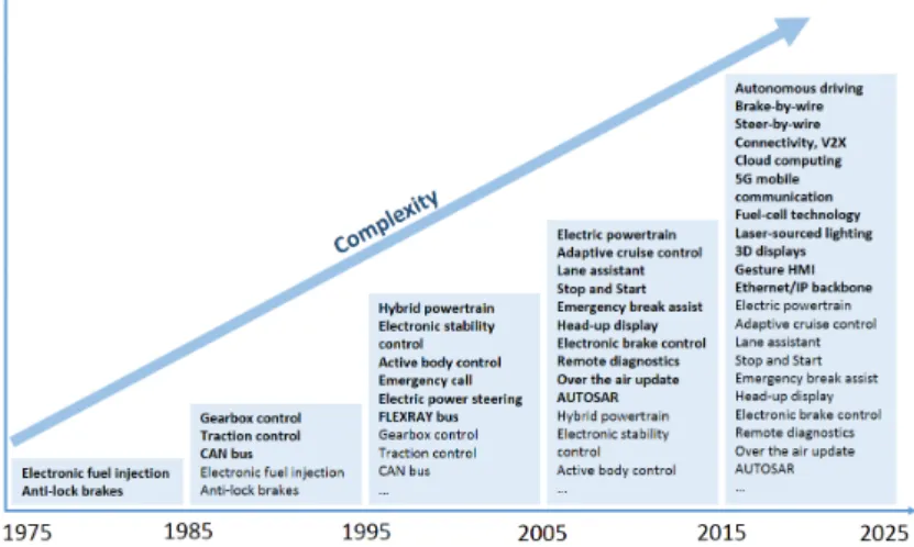
However, as the importance of electronics and software has grown, so has complexity. As portrayed in Figure 1, the complexity of software-based auto-motive functions is increasing rapidly.
Figure 1: Automotive innovations and complexity
To some extent, we can observe a link between the complexity and the num-ber of softwareLines Of Code (LOC)contained in a modern car. In 2010, some vehicles had about 10 millionLOC; by 2020, this expanded by a factor of 10, to roughly 100 million lines.
1.2 p r o b l e m
The effort to verify these systems increases with the amount of software to ver-ify. Nowadays, test scenarios and peer reviews are used during the verification process but it is practically impossible to test all the combinations of possible states in which the system can be put. And in practice, it is not necessary to make such an effort for all the embedded software because only a little part can be considered as critical. For example, a radio that reboots during driving cannot harm the passengers of the car but if the front lights go off during night driving it can cause fatalities. Therefore, it is important to have the highest ro-bustness and reliability for those functions that are safety-related and that have a potential impact on human lives or can cause economic losses.
Model-based design has been introduced to cope with the complexity issue and with the cost of fixing bugs that are found during the late phases of the design. By allowing the simulation of a model of the software in the early design phases, Model Based Design allows fixing the model as soon as possible
1.3 research objectives 3
and limiting the propagation of errors down to the implementation. However, similar to testing, simulation suffers from the same limitations: the number of scenarios to be checked in a model to get full confidence goes beyond any reasonable subset of scenarios that can be examined in practice and cannot guarantee the absence of errors for highly critical systems.
A way to bring higher guarantees for safety-critical software systems is to use formal verification techniques. Formal methods are techniques based on math-ematical logic, which goal is to bring in the software and hardware verification the same rigorous mathematical background already used by other engineering disciplines. Formal methods can be seen as exhaustive testing but need some methodologies and tools in order to be used in practice by non-expert software engineers.
1.3 r e s e a r c h o b j e c t i v e s
The work presented in this thesis focuses on the introduction of formal meth-ods in an automotive industrial context in order to bring more guarantees and robustness for the safety-critical part of the embedded software. Indeed, there is a gap to bridge between the formal methods capabilities and the systems and specifications present in the industry. In practice, verification of arbitrary func-tional properties on realistic systems often requires expert knowledge about the analyzed system and verification technique(s) used. The spread of formal verification in the industrial community is hindered by this need for costly and time-consuming expert intervention. Our work contributes to the understand-ing of how formal methods can be used by the engineers and for what type of scenario.
The goal of this thesis is also to improve on the state of the art of formal verification in our application domain by:
• studying the use of formal methods in other industries (railway, aviation) and identify which techniques are used and at which design stage; • experimenting with different formal methods on representative
automo-tive models and code in order to get an insight on their limitations and eventually find workarounds;
• proposing methodologies that could be used by non-expert engineers and use cases on which they could be applied.
1.4 c o n t r i b u t i o n s
To achieve these goals, we studied in the literature the industrial use of existing formal methods – abstract interpretation, model checking, deductive proof – and then applied them to some automotive use cases.
4 i n t r o d u c t i o n
We proposed a new algorithm for invariant generation for symbolic model checking of properties involving time. It provides useful relational invariants based on a template that strengthen the inductive proof.
We also proposed a mutation framework to measure the coverage of the proved properties, which is important when using formal methods in a certi-fication context. In this context, a demonstration of the coverage of the proof when using formal methods is generally required.
Finally, our experiments served to propose some methodologies that can be used by serious (motivated) non-experts software engineers. These methodolo-gies go from providing contracts for the inputs and outputs of the designed functions to how to describe in a formal way what the function is expected to do, where to find good requirements that can be formalized, what are the strategies to begin with and how to structure the proved function and its formal requirements.
1.5 p l a n
We divided this thesis as follows:
• Chapter 1: introduces the PhD work and states the challenges we tackle. • Chapter 2: presents the industrial context in which our work evolves. • Part 1: Formal methods and Certification standards presents the
automo-tive context
– Chapter 3: presents an overview of the safety standards.
– Chapter 4: presents the formal methods from the theoretical founda-tions to the applicafounda-tions that can be found in the industry today. • Part 2: Automotive embedded software design using formal methods
presents our contributions
– Chapter 5: presents some methodologies that can be applied by en-gineers and some hints for writing formal properties.
– Chapter 6: presents our new improved invariant generation algo-rithm for long duration properties and its integration in JKind.
– Chapter 7: proposes an efficient algorithm and a new coverage met-rics for evaluating the quality of properties that are proved valid using model checking.
– Chapter 8: presents our experiments with automatic deductive proof of a discrete-valued function calculating a square root.
2
A U T O M O T I V E S O F T WA R E D E S I G N A N D D E V E L O P M E N T
There is not a vehicle currently available to US consumers that is self-driving. Every vehicle sold to US consumers still requires the driver to be actively engaged in the driving task, even when advanced driver assistance systems are activated. If you are selling a car with an advanced driver assistance system, you’re not selling a self-driving car. If you are driving a car with an advanced driver assistance system, you don’t own a self-driving car.
— Robert Sumwalt (2020, Feb. 25), Chairman of National Transportation Safety Board The modern car has evolved from a mechanical device to a distributed cyber-physical system, which relies on software to function correctly. Starting from the 1970s, the amount of software and electronics used in a car has gradually increased from as little as oneElectronic Control Unit (ECU)to as much as 150 in 2020.
The main reason to introduce electronics in the 1970s was the 1973 oil crisis followed by another oil crisis in 1979. We needed to reduce the fuel consump-tion, and electronic engine control helped in doing so. Another reason was the introduction of safety-related functions such as Anti-lock Braking System (ABS)in the early 1970s preventing the wheels from locking up during brak-ing. But the part of embedded software significantly increased since 2000 with the introduction of driver assistance functions. At the beginning, it was simply for Cruise Control and then it was coupled with a radar to have an Adaptive Cruise Control adjusting automatically the car speed to the front vehicle speed. Today the radar can be coupled with a camera and control the braking in case of emergency, keep the lane in traffic jams or on highway, thus taking control over the steering wheel. Since 2010, we observe the evolution of new advanced connected services and infotainment systems based on the Linux kernel, which have significantly contributed to the increase of the number of lines of code in the car, achieving 100 million lines of code.
The software in a modern car provides plenty of new opportunities, but it also requires to be more careful in the design, implementation, verification and validation phases. Although the practices in software engineering include
6 au t o m o t i v e s o f t wa r e d e s i g n a n d d e v e l o p m e n t
methods and tools to respect safety and security requirements of the software, they are often applied in an automotive-specific manner.
Today we can clearly see that the automotive industry is moving to a field less dominated by mechanical engineering but with a growing part of electronic and software engineering. The trend of using software will continue to increase and there is a need for professional software engineering. To maintain a higher quality level of the software, we need to have rigorous processes of software engineering, providing guarantees that the software will not be harmful to its users.
One of the good practices in software engineering is the high-level design of software systems, referred to as software architecture. The software architecture offers the possibility to define how the software functions are distributed on software components, what interface mechanisms they use and how compo-nents interact with each other.
The other important phase in the software design is its verification. This phase is of a greater importance, in particular when developing highly critical safety systems. Testing is the general practice but we can also use formal meth-ods for some parts of the software and obtain higher confidence that bugs are absent.
In the following, we describe each phase of the automotive software develop-ment process and discuss it from a verification point of view.
2.1 t h e v-model
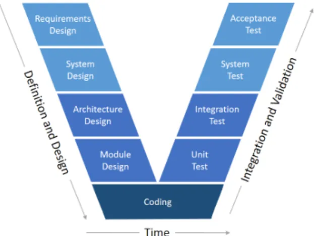
The V-Model shown inFigure 2is the mostly used methodology today for devel-oping embedded software in the automotive industry. However, new method-ologies brought from the software engineering (agile/scrum) start to break through.
2.2 requirements engineering 7
The V-Model is a full life cycle methodology that emphasizes the importance of testing. Actually, tests are designed in parallel with each phase of the life cycle. This early design of test cases with each development phase can be an effective way for early defect detection and removal. This method can be con-sidered an extension of the waterfall model.
ISO 26262, the standard for functional safety of road vehicles, proposes also to use the V-Model as a reference phase model for the product development at the software level [ISO18].
The V-Model is suitable for developments in which requirements are well defined and stable, and the technology to be used is well understood. This is especially necessary in a certification context for safety-critical software. The safety assessor needs to have a stable documentation of the project to be able to analyze it within a given time.
2.2 r e q u i r e m e n t s e n g i n e e r i n g
As we saw in the previous section, the first and very important phase required by the V-Model and the ISO 26262 standard is to completely elicit and docu-ment all the requiredocu-ments necessary for the project prior to the actual develop-ment.
Definition 1 (Requirement)
(1) A condition or capability needed by a user to solve a problem or achieve an objective.
(2) A condition or capability that must be met or possessed by a system or sys-tem component to satisfy a contract, standard, specification, or other formally imposed documents.
(3) A documented representation of a condition or capability as in (1) or (2). [IEEE 610.12-1990] This work is done by the system engineer who captures the needs from differ-ent stakeholders (marketing, regulations, etc.) and writes down textual require-ments of what the system is expected to do. Each requirement has a unique number and a version and is stored in a database. If a requirement should be changed, its version is incremented.
2.2.1 Requirement Types
In the literature [Poh10] and many requirement engineering standards, three main types of requirements are generally presented :
8 au t o m o t i v e s o f t wa r e d e s i g n a n d d e v e l o p m e n t
• Functional requirements • Quality requirements • Constraints
Functional requirements specify the functionalities/services that the system should or should not provide. Different levels of functional requirements can exist depending on the level of details. Requirements defining the data, func-tions and behavior of the system are in most cases solution-oriented since they are defined in a way that mainly supports the realization of the system. They de-scribe how the system should be developed. An example for such a requirement can be the following statement: “When LightSwitch = ManualON and Ignition = ON Then LightsOutput = ON Else LightsOutput = OFF.”. In contrast, user require-ments are more abstract and give the goals of the system in a solution-neutral way. They describe the problem or what the system is expected to do. An ex-ample for such a requirement can be the following statement: “If the brakeECU
detects a fault, the system shall inform the user by showing an alert message.”. Quality requirements specify quality properties such as performance, reliabil-ity, stability for entire system or for a component, service or function. Very often, they influence the architecture of the system. An example for such a re-quirement can be the following statement: “When LightsOutput changes its value the application module should emit the new value on the network in less than 50 ms.”. In practice, the term “non-functional requirements” is sometimes used but very often it refers to either quality requirements or underspecified functional re-quirements. In the reference book about Requirements engineering [Poh10], the author recommends avoiding the category of “non-functional requirements” when writing specifications. He proposes to classify them as quality require-ments or refine them to functional ones.
Besides defining functional and quality requirements for a system, constraints are also documented during the requirements design phase. They are organi-zational or technological requirements that restrict the development process or the properties of the system to be developed. They have different origins: cul-tural, legal, physical, project and so on. An example for such a requirement can be the following statement: “The source code should be Motor Industry Software Reliability Association (MISRA)compliant.”.
2.3 s o f t wa r e a r c h i t e c t u r e
Software architecture is fundamental for the automotive software design. It is a high-level design view of the system and combines multiple views used to communicate with the project teams. It is also used to make technical decisions about the organization of the functionalities of the system. The software archi-tecture can help understanding and predicting the performance of the system before it is designed.
2.3 software architecture 9
2.3.1 AUTOSAR
AUTomotive Open System ARchitecture (AUTOSAR) is a global partnership between automotive actors founded in 2003. Its objective was to create and es-tablish an open and standardized software architecture for automotiveECUs. It defines the reference architecture and methodology for the development of au-tomotive software systems and provides the language (meta-model) for their architectural models.
Today,AUTOSARproposes two main platforms: the Classic Platform1
and the Adaptive Platform2
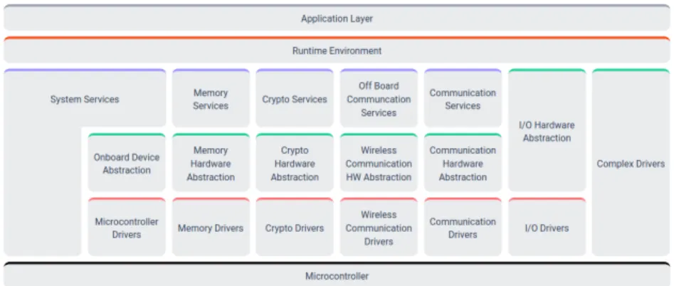
. To give an example, inFigure 3, we show the Classic Platform, which contains three software layers:
• an application layer calledApplication Software (ASW);
• a middleware software represented by theRuntime Environment (RTE); • aBasic Software (BSW)including the real-time operating system and
ser-vices.
Figure 3: AUTOSAR Classic Platform Release R19-11
The application layer is composed of hardware-independent software and contains application modules (components) that are visible and used by the fi-nal user. It is in this layer that formal methods are most valuable to be deployed because these modules are updated more often than the operating system and the low-level services (BSW). Another reason is that most of the modules are model-based and thus can support model checking.
TheRTEis automatically generated during compilation phase. It is used for managing communications between application software components and for communicating with the BSW services. The BSW provides different services that are specified by the standard and the operating system. As the services are standardized byAUTOSARand the operating system shared between multiple car manufacturers, we can consider their validation done by the practice.
1 AUTOSAR Classic Platform:https://www.autosar.org/standards/classic-platform
10 au t o m o t i v e s o f t wa r e d e s i g n a n d d e v e l o p m e n t
2.3.2 AUTOSAR and Software Verification
From the perspective of this thesis, theAUTOSARstandard is important in the sense that it formalizes some important elements about the system that can be used for software verification, even if not using mathematical logic. We can use them for example to extract semantic information about the software such as specific types declaration for physical dimensions (speed, acceleration, time). They can be used to facilitate the proof of some properties combining objects of same type together to generate more useful invariants. We discuss this topic inChapter 6.
As in the AUTOSAR definitions we can find the ranges for the inputs, out-puts, internal variables, other parameters, we can automatically extract this in-formation to help the deductive proof of a function or the static analysis based on abstract interpretation. For the deductive proof, we could provide contracts in the form of pre-/post- conditions that normally take a lot of time to be written manually. For the sound static analysis, we could provide assertions to obtain more precision reducing thus the amount of false alarms. This could be the subject of a future work.
2.4 m o d e l-based design vs manual coding
Traditionally, the entire software of the car was written manually based on the low-level detailed software requirements. Assembly language was used at the beginning but it was progressively replaced by higher-level languages such as C or C++.
Today, the trend is to replace C programming by higher-level domain spe-cific languages for some part of the control software. The principle is to make a model of the needed functional behavior by simply dragging and dropping library blocks and linking them. The obtained specification model is then simu-lated by the designer to check if its behavior corresponds to the specification. Once the specification model is validated there are two ways to embed it in the ECU. The oldest one was to use the model as software specification and write manually the code corresponding to the model. This method could be error-prone and time consuming. That is why the preferred method today is to transform the specification model into a design model that can be used to gener-ate the code for the targetECUautomatically. The design model is optimized to fit in theECU’s memory and resources and integrates theAUTOSARroutines and other system libraries not present in the specification model.
2.4.1 Traditional Manual Coding
After the system requirements have been written and allocated to anECU, a software architecture is defined for it and the design of the software modules
2.4 model-based design vs manual coding 11
can begin. This process consists of refining the system specification to have a new detailed specification ready for implementation by the software developer. This specification looks like pseudocode and uses the names of the variables that will be present in the final code. However, it can abstracts some complex services or routines that the developer is aware of. For example, it can require calculating a square root with some precision without providing technical de-tails how it should be calculated. The software developer uses C or C++ lan-guages to code this detailed specification. The module is then compiled and unit tests are run to verify its behavior. Coverage tests are also run to check the coverage of the code, and static analysis is used to check the MISRA compli-ance and the presence of run-time errors. The code is then reviewed by another person that was not involved in the coding. After its approval, it is integrated, compiled with the target compiler and tested again as a black-box. The inte-gration is a complex process in which a set of application modules that are compatible with each other are assembled with the basic software (real-time operating system, network services, memory services, etc.), parameter values chosen for the concrete project, and all the AUTOSAR glue is generated and assembled with the rest. Because of the generic nature of the software (it can goes on multiple vehicle projects), there can be a few thousand parameters to be configured.
The choice of the programming language depends on the problem to be treated: C is commonly used because it provides an optimized code necessary for the embedded micro-controllers that have limited resources. Assembly lan-guage is still used for some low-level functions of the operating system, even in modern multi-core real-time operating systems. C++ is more suitable for data-oriented functions where a large amount of data need to be processed, such as
Advanced Driver-Assistance Systems (ADAS)3
functions. 2.4.2 Model-Based Design
Model-Based Design (MBD), as the name supposes, uses models for the design of software. The model should reflect the behavior of the function of a car and is created in a formalism that reflects the physical world rather than the software world. Different kinds of models may exist: Physical process model, Environ-ment model, Prototyping model, System model, ImpleEnviron-mentation model, and so on.
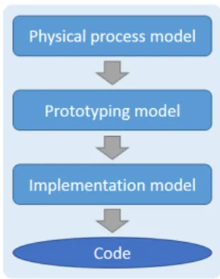
Designing using models has impacts on the design process and the compe-tence of the designers, who should be trained before using a modeling tool. A typical process is shown inFigure 4.
The process starts with the description of the function of a car as mathemat-ical equations defined by the inputs, the outputs, and a focus on the internal data flow between them. At this stage, the designer often operates by using
12 au t o m o t i v e s o f t wa r e d e s i g n a n d d e v e l o p m e n t
Figure 4: Model-based design process
mathematical models and ignores some practical issues such as the modular arithmetic used by computers, the precision of the floating-point numbers, the limited size of the memory, etc. The difference between reasoning with mathe-matical numbers and the implemented code can result in divergence of the final behavior from the one that was calculated with the mathematical model. After the physical process is modeled, simulated and validated, two other models are developed to prepare and produce the code: a prototyping model and an imple-mentation model. The prototyping model is used to verify the behavior of the entire function within its environment. Generally, this model is not optimized to run on a micro-controller. The implementation model is an optimization (CPU usage, memory consumption) and adaptation of the prototyping model that integrates AUTOSAR routines. This adaptation is error-prone: overflows and different behaviors can appear and should be verified, using for example the same simulation scenarios that were used during prototyping.
Once the implementation model is completed and validated, it is used to generate the code in the target programming language – usually C.
There are two types of code generators: unqualified (example: Embedded Coder for Simulink) and qualified (example: SCADE Suite Compilator (KCG)
for SCADE Suite). The difference is that for an unqualified code generator the code should be reviewed and additional testing called back-to-back testing should be done to demonstrate that the model and the code have the same behavior. Back-to-back tests are tests that have a good coverage ratio and such that their results are the same for the model and for the generated code. With a qualified code generator, the behaviors of the model and the code are guar-anteed by the tool certification to be the same. In this case, a generated code review and a back-to-back testing are not necessary.
2.5 t o wa r d s t h e au t o n o m o u s c a r
Research projects in innovation stimulated by public authorities around the world aim to clear the way for a step-by-step introduction of automated
vehi-2.5 towards the autonomous car 13
cles. The projects comprise a number of aspects like standardization, testing, safety, or in-vehicle technology. As mentioned in [noa15] it is expected that automated driving will:
• Improve safety by reducing human driving errors • Significantly contribute to the optimization of traffic flow • Help to reduce fuel consumption and CO2emissions
• Enhance the mobility of elderly people and unconfident drivers
Several forecasts [WH16] predict a limited availability of automated driving functions at level 2 and 3 (partial and conditional automation) in 2020 and a wide availability by 2040 until level 4. Today’sADASsuch asAdaptive Cruise Control (ACC),Lane Keeping Assist (LKA), orPedestrian Detection (PD)will form the backbone of tomorrow’s mobility. Vehicles will communicate with each other and with the infrastructure. Vehicle-to-Vehicle (V2V) communica-tion will allow vehicles to exchange traffic data informacommunica-tion (e.g. nearby ac-cidents) and data about their driving intention.Vehicle-to-Infrastructure (V2I)
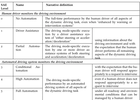
communication will be used to optimize the road traffic and thereby will help to reduce pollution. The role allocation between a human driver and an auto-mated driving system in this scenario is specified by theSociety of Automotive Engineers (SAE)as six levels of driving automation going from no automation to full automation (seeTable 1).
SAE Level
Name Narrative definition
Human driver monitors the driving environment
0 No Automation The full-time performance by the human driver of all aspects of the dynamic driving task, even when "enhanced by warning or intervention systems"
1 Driver Assistance The driving mode-specific execu-tion by a driver assistance sys-tem of "either steering or acceler-ation/deceleration"
2 Partial Automa-tion
The driving mode-specific execu-tion by one or more driver as-sistance systems of both steering and acceleration/deceleration
using information about the driving environment and with the expectation that the human driver performs all remaining aspects of the dynamic driving task
Automated driving system monitors the driving environment 3 Conditional
Au-tomation
with the expectation that the hu-man driver will respond appro-priately to a request to intervene 4 High Automation even if a human driver does not respond appropriately to a re-quest to intervene
5 Full Automation
The driving mode-specific performance by an automated driving system of all aspects of
the dynamic driving task under all roadway and environ-mental conditions that can be managed by a human driver
14 au t o m o t i v e s o f t wa r e d e s i g n a n d d e v e l o p m e n t
There is a key distinction between level 2 (“Partial Automation”) and level 3 (“Conditional Automation”) as in the latter case the system performs the entire dynamic driving task (execution of steering, acceleration, braking and monitoring of the environment). In contrast to level 4 (“High Automation”), in level 3 the driver is expected to be ready for taking over the control upon demand (within a predefined time period e.g. 10 seconds) at all times. At level 4, the driver is no more asked to take over the control.
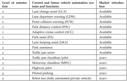
We present inTable 2a brief overview of driver assistance systems that have already been introduced or systems that are on the way to be introduced in the market. The majority of the systems today are level 1 or 2. Levels 3 and 4 are still under development.
Level of automa-tion
Current and future vehicle automation sys-tems and functions
Market introduc-tion
0 Lane change assist (LCA) Available 0 Lane departure warning (LDW) Available 0 Front collision warning (FCW) Available 0 Park distance control (PDC) Available 1 Adaptive cruise control (ACC) Available
1 Park assist (PA) Available
1 Lane keeping assist (LKA) Available
2 Park assistance Available
2 Traffic jam assist Available 3 Traffic jam chauffeur/pilot 2020+ 3 Motorway chauffeur (MWC) 2020+
3 Highway pilot 2020+
4 Piloted parking 2020+
5 Robot taxi (fully automated private vehicle) 2030+
Table 2: Summary of current and future vehicle automation systems and functions
Figure 5illustrates the Groupe PSA’s “Autonomous Vehicle for All” program roll-out. The first level 3 functions to be proposed by the group will beTraffic Jam Chauffeur (TJC)andHighway Chauffeur (HC)respectively for automated driving in traffic jams and on highways.
There is an important liability gap between levels 6 2 and levels > 3. Actu-ally, for levels up to level 2 the driver is responsible for the entire driving, the assistance functions only assist him. Functions at levels > 3 can take the con-trol over the driving for some period of time. If there is an accident during this period, the car manufacturer’s liability can be engaged for production defects: manufacturing defects, design defects, incorrect or missing instructions. 2.6 p r ov i n g t h e s a f e t y o f t h e au t o n o m o u s v e h i c l e
To help proving that the critical software of an autonomous vehicle is safe, we propose in this thesis to introduce formal methods in some parts of the
2.6 proving the safety of the autonomous vehicle 15 Figur e 5: Gr oupe PSA ’s “A utonomous V ehicle for All” pr ogram roll-out
16 au t o m o t i v e s o f t wa r e d e s i g n a n d d e v e l o p m e n t
development process. We expect that if autonomous cars are to be massively launched in the future, the authorities could require their certification, as is actually the case for the railway and aviation industries. Probably, the machine learning algorithms could not be certified because they have no specification to be verified that they respect. Internal experiments at Groupe PSA have shown that machine learning algorithms are not 100% reliable. To guarantee the safety of the passengers, they should be supervised by simpler algorithms developed in a classical manner (based on requirements). Supervising consists in checking that the results (the outputs) of the executed complex function correspond to what is defined by the specification and expected by the supervising function. Otherwise, the supervisor takes over and put the system into a safe mode. For an autonomous vehicle, this safe mode could be to stop in the emergency lane on the highway. The critical part of the software is then the supervisor, which could be certified.
The supervisor is not a new concept. It already exists in the trains and can for example decide to activate the emergency braking when the autopilot is not reacting well. In this case, the supervisor has the highest critical level (SIL 4) and is certified at that level.
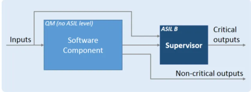
The general principle of a supervisor and a supervised modules is shown in
Figure 6. It consists of a supervised function, for which a basicQuality Manage-ment (QM)is sufficient. It means that this function has no Automotive Safety Integrity Level (ASIL)4
level and is not considered critical. This function may be too complex to be verified, for instance containing complex algorithms or even neural networks. In order to control that its critical outputs obey the spec-ification, we use a supervisor module, which is critical (ASIL A to D) and is developed using traditional verification and certification methods.
Figure 6: Example of a supervisor monitoring a software component
Today, there are already multiple supervisors in the automotive software. For example, if there is a problem with the lighting control software, a supervisor can take over and turn on the lights. The different strategies and mechanisms used at Groupe PSA, such as supervision and partitioning for coexistence of critical and non-critical modules, are discussed in [MBF18].
2.7 conclusions 17
One of our targets for the formal methods application are the supervision modules. They are intended to be simple and they are based on clearly defined safety requirements. We want to obtain a proof that no matter what happens, the safety requirements expressed as safety properties will be respected by the software without exceptions. A safety property is generally invariant and should always be true.
The other potential targets for the application of formal methods in the auto-motive software are the source code analysis based on abstract interpretation to prove the absence of run-time errors or estimate the Worst-Case Execution Time (WCET)and the unitary function proof based on deductive methods. 2.7 c o n c l u s i o n s
This chapter presented the context in which the automotive embedded software is developed in respect to the safety standard ISO 26262. We introduced the V-Model, based on the central notions of specification and requirement. New methodologies such as Agile are being currently introduced. They need to be adapted if a certification of the software were required in the future.
We briefly presented AUTOSAR, which defines the reference architecture and methodology for the development of automotive software.AUTOSARis a great source of inspiration for research because it offers a quantity of data that can be used to verify the software in different ways.
We presented theMBDparadigm, which is more and more used for design-ing software components in replacement of the traditional manual coddesign-ing.
We presented the way towards the autonomous car. Today most of the driver’s assistance systems are level 2 but in the next years level 3 will probably appear and become the standard.
We presented how a complex software module can be supervised. These supervisors are of a particular interest for the application of formal methods because they are simpler than the supervised module and are based on a safety specification, which can be formalized and proved.
In the next chapter, we present an overview of the safety standards to under-stand what could be necessary to prepare for the autonomous vehicles tomor-row.
Part I
F O R M A L M E T H O D S A N D C E R T I F I C AT I O N
S TA N D A R D S
3
S A F E T Y S TA N D A R D S A N D C E R T I F I C AT I O N
All too often, writers of standards focus on questions of what constitutes good practice, and lose sight of what the followers of those standards truly need to demonstrate in order to show safety. Safety is demonstrated not by compliance with prescribed processes, but by assessing hazards, mitigating those hazards, and showing that the residual risk is acceptable.
— A. Rae (2007). Acceptable Residual Risk: Principles, Philosophy and Practicalities. 2nd IET International Conference on System Safety. The correctness and the quality of the embedded software play a key role in the safety as a whole. To ensure safety, engineers make a significant effort to show the correctness of individual subsystems and their integration using testing or simulation. They eventually need to certify that the developed vehicle as a whole is indeed safe using artifacts and evidences produced during the development process. Such a certification process can help to increase the safety confidence in the product and to reduce the automaker’s liability.
However, software certification in the automotive domain is not yet a com-mon practice compared to other safety-critical domains, such as aviation, rail-way, nuclear and medical [YLK16]. Even if the safety standard ISO 26262 has been well adopted, the authorities do not require for the time being to certify the car’s software. It is probably because the driver is still responsible for the driving task but with the advent of higher levels of automation, things could change.
3.1 s a f e t y s ta n d a r d s 3.1.1 Why do we Need Standards?
In some areas, we can easily imagine the usefulness of the standards. For ex-ample, the electronic devices that we buy have a standard electric plug (for a country or a continent) and we can plug it to a standard electrical socket. The size of the car’s tires and some other pieces are standardized in order to replace them easily.
22 s a f e t y s ta n d a r d s a n d c e r t i f i c at i o n
For safety-critical software, it is less obvious why we need a standard. Actu-ally, it comes from the disasters people have experienced. A disaster occurs and people ask that it never occurs again. It results in a standard written by some experts to which the industry must comply. It generally results in increased product quality and provides a better protection for the users.
Standards can also be useful to new companies for their product develop-ment. They can find some good practices, techniques and tools listed in the standard. In the event of a court case, if a company complies with a standard it can defend itself by claiming they are following the industry best practices.
Another point of view is that of a company that wants to buy a safety-critical system for which the standard helps formalizing the contract. It is easier to require that the product must comply with ISO 26262 at ASILB level than to write the explicit conditions of acceptable failure rate, tools to be used for the development process, and so on.
3.1.2 Goal- and Prescription-Based Standards
The standards can be classified into two categories: prescriptive and goal-based [Hob15].
Prescriptive standards prescribe and proscribe means: processes, procedures, techniques and tools. If a certificate were issued for a prescriptive standard, a company could for example claim that their product meets the requirements of ISO 26262 standard.
Goal-based standards, in contrast, require some goals to be achieved and leave the selection of appropriate processes, techniques and tools to the development organization. This type of standard needs more effort to be done by the devel-opment team because they need to not only define their processes but also justify their adequacy. The auditing for certification is also much more diffi-cult because there is no checklist of prescriptions to be checked. However, if a certificate were issued to a company, it could in principle claim that their prod-uct is safe. The avionics standard, DO-178C, is probably the most goal-based standard that exists today.
3.1.3 Functional Safety and IEC 61508 Derivated Standards
Functional safety can be described as the part of the safety of a system that depends on automatic protection operating correctly in response to its inputs or failure in a predictable manner. For example, if for some reasons (software bug, component failure, etc.) the car’s lights switched off when they should be on (driver has requested them, or in automatic mode when it is dark) a safety function that permanently monitors the conditions can decide to turn them on to protect the driver.
3.1 safety standards 23
IEC 61508 is a basic and maybe the most important standard for functional safety from which are derived some other standards for different industries. The standard is entitled Functional Safety of Electrical/Electronic/Programmable Electronic Safety-related Systems and covers general project management and the development of hardware and software components.
The standard considers that a piece of equipment can give rise to safety hazards and it should be accompanied by a safety function that monitors it and moves it into a safe state when a hazardous situation is detected.
From a software development point of view, the most interesting part is the prescription of tools and techniques that are not recommended, recommended or highly recommended for each stage of the software development life cycle.
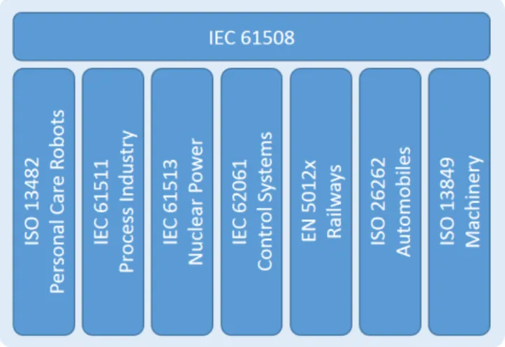
IEC 61508 has been specialized for a number of industries as shown in Fig-ure 7. The linkage level between IEC 61508 and the industry-specific standards varies between industries. The railway standards (EN 5012x), are probably the closest to IEC 61508. The medical standard IEC 62304 is not considered a deriva-tion from IEC 61508 because it is not directly concerned by funcderiva-tional safety. The aviation standard DO-178C is another example of standard that is not de-rived from IEC 61508.
Figure 7: Derivation of safety standards from IEC 61508
3.1.4 Railway – IEC 62279 / EN 5012x
IEC 62279 provides a specific interpretation of IEC 61508 for railway applica-tions. It reuses from IEC 61508 theSafety Integrity Level (SIL)levels (SIL0to 4,
SIL4is the most critical) and is intended to cover the development of software for railway systems. On the other hand, CENELEC emitted a set of EN stan-dards for railway applications such as EN 50126 (system), 50128 (software) and 50129(hardware). In EN 50128, the requirements forSIL3are the same as for
24 s a f e t y s ta n d a r d s a n d c e r t i f i c at i o n
SIL4, and the requirements forSIL1are the same as forSIL2. So in practice, only three levels are used:SIL0,SIL1/2 andSIL3/4. We can note that inSIL 3andSIL4formal methods are highly recommended.
3.1.5 Medical – IEC 62304
IEC 62304 is a standard, which specifies life cycle requirements for the develop-ment of software within medical devices. It defines three classes of risk: Class A when no injury or damage to the health of a patient or device operator would result if the software failed; Class B if non-serious injury is possible; Class C if death or serious injury is possible (pacemakers, defibrillators, etc.). IEC 62304 focuses exclusively on processes (software development, management and configuration) and its only reference to formal methods is somewhat nega-tive. Paragraph 5.2.6 states, “This standard does not require the use of a formal specification language.”
3.1.6 Aviation – DO-178C
DO-178C/ED-12C, called “Software Considerations in Airborne Systems and Equipment Certification” provides guidance to the development of safety-critical avionics software and is used for its certification. It was jointly devel-oped by Radio Technical Commission for Aeronautics (RTCA)and European Organisation for Civil Aviation Equipment (EUROCAE) and defines five dif-ferent critical levels for the software named Design Assurance Level (DAL): Catastrophic (A), Hazardous (B), Major (C), Minor (D); No effect (E). They are determined from the safety assessment process and hazard analysis by exam-ining the effects of a failure condition in the system.
DO-178C is particular in that it does not provide prescriptions on tools and techniques to be used. Instead, it provides objectives that should be achieved, which is more difficult but the system is considered safer compared to prescription-based standards.
DO-178C also provides the following supplements for tool qualification and technologies:
• DO-330 “Software Tool Qualification Considerations”;
• 331 “Model-Based Development and Verification Supplement to DO-178C and DO-278A”;
• DO-332 “Object-Oriented Technology and Related Techniques Supple-ment to DO-178C and DO-278A”;
3.2 certification and qualification 25
We are particularly interested in DO-333, which provides guidelines how formal methods can be applied in a certification context and which activities they can replace.
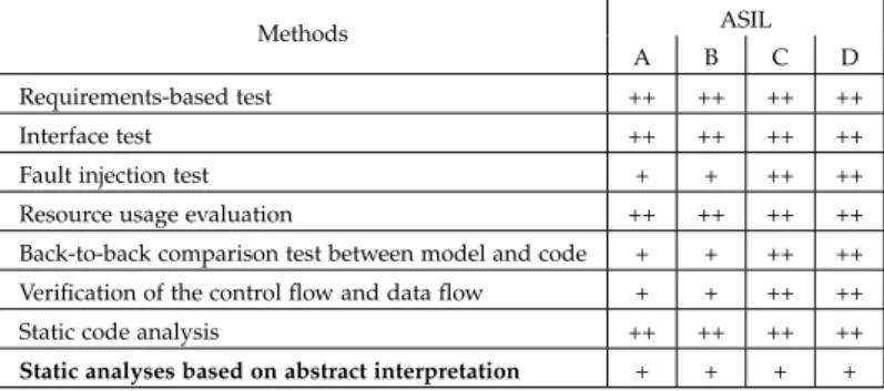
3.1.7 Automotive – ISO 26262
ISO 26262 is the specialization of IEC 61508 for the automotive domain. Part 6 deals with software and includes tables of recommended (+) and highly-recommended techniques (++) for different phases of the development process and for each Automotive Safety Integrity Level –ASIL(from level A to D, D is the most critical).ASILreplaces the concept of IEC 61508’sSILwhich is based on probability of failure per hour of use. Instead, in ISO 26262 the events that could cause injury are listed and anASILis calculated (using a table proposed in the standard) for each of them by considering three aspects:
• Severity (S0 to S3): classifies the type of injuries that could result from this event;
• Probability of Exposure (E0 to E4): probability that the event occurs in nor-mal operation;
• Controllability (C0 to C3): classifies the difficulty of the driver to control the situation and avoid injury.
For example, a hazardous event combining S3 (fatal injury), E4 (high probabil-ity) and C3 (uncontrollable) is assigned to ASILD level. For many positions, there is noASILlevel assigned – “QM” is listed instead. It means that there is no requirement to comply with ISO 26262 but the product must be developed in accordance with a quality management process approved in an international standard such as ISO 16949 or ISO 9001.
In [YLK16], Toyota prepares the advent of the certification by providing a survey of the software certification approaches in different domains (aviation, medical, railway). They propose to use assurance cases as a promising tech-nique to automotive software certification. The authors also point out that even if ISO 26262 provides some recommendations to improve the software quality, it does not provide a quantified and rigorous process for software certification. 3.2 c e r t i f i c at i o n a n d q ua l i f i c at i o n
The quality of the safety-critical embedded software has been, for many years now, ensured by applying precise and constraining development processes on each activity of the system development: from requirements elicitation to inte-gration of the embedded code through software design, code production and code verification. For each of these activities artifacts are produced aiming at
26 s a f e t y s ta n d a r d s a n d c e r t i f i c at i o n
providing evidence of the means used for the activity achievement. These arti-facts are mandatory to provide parts of the information required by the certifi-cation bodies.
Certification stands for the process of ensuring that a product (system or equipment) is “approved” for use. When a company wants/needs to certify a product against a particular standard, it can self-declare that the product meets all the requirements of the appropriate standard, possibly asking an external auditing company to confirm the declaration. Alternatively, the company could employ an independent certification body to assess and certify the product.
In order to be able to emit certificates, the certification body must be ac-credited to issue certificates for a particular standard. Certification bodies are accredited by national accreditation authorities to carry out particular certifica-tions. There is no accreditor for the accreditation authorities – they verify each other’s compliance in continuous evaluations.
Qualification is used in the context of tools when these ones are expected to be used for the “elimination, reduction or automation” of certification activities “without its [the tool] output being verified” [DO-178C]. Each standard defines different levels of qualification e.g. from TQL-1 (the strongest) to TQL-5 (TQL stands for Tool Qualification Level) in DO-178C or TCL-3 (the strongest) to TCL-1 (TCL stands for Tool Confidence Level) in ISO 26262. The approach of qualification is also different between avionics and automotive standards. For avionics, according to the chosen TQL, a specific set of objectives have to be fulfilled to ensure the tool qualification. For the automotive, it is based on the confidence of the tools and their error detection capabilities (ISO 26262, part 8). For example, a code generator (can introduce bugs when generating a code from a model) is permitted to be used without qualification (TCL-1) if it is accompanied by qualified error detection tools.
3.3 c o n c l u s i o n s
In this chapter, we introduced some safety standards, their usefulness and no-tions about certification and qualification. Some of the standards are more rig-orous because they require achieving objectives instead of giving prescriptions to follow. Some of them are also proposing to use formal methods, which is a good motivation for their application in the industry.
In the next chapter, we present the formal methods from their theoretical foundations to their concrete applications in the industry.
4
F O R M A L M E T H O D S – F R O M T H E O R Y T O P R A C T I C E
Formal methods should be part of the education of every computer scientist and software engineer, just as the appropriate branch of applied mathemat-ics is a necessary part of the education of all other engineers.
— John Rushby, SRI International Engineering, as a whole, relies on mathematical models to take decisions about the design. However, software development has traditionally been less formal by using testing to confirm its goodness. The goal of formal methods is to bring the same rigorous mathematical background already used by other engineering disciplines to both software and hardware. Formal methods apply mathematical logic and discrete mathematics to model the behavior of a system and formally verify that the model of the system satisfies the properties that it is expected to have. Generally, the expected properties are written as a set of requirements called a specification. The properties can be functional or safety. It is practically impossible to verify all the functional properties because a simple embedded computer can have more than twenty thousand requirements allo-cated. Thus during the design of the system specification, the important prop-erties should be identified. They are not necessarily only safety-related but can also be security-related or even effects seen by the user that could reduce its confidence in the system e.g. a radio-navigation that is rebooting frequently is not safety-related problem but the user could doubt about the quality of the rest of the system. Finally, formal verification can be seen as exhaustive testing and yielding systems of a very high dependability in a cost-effective manner.
Basically, a formal method is a formal model and a formal analysis. Even if formal models can benefit the software development process e.g. for auto-matic code generation, the most beneficial aspect from our point of view is the formal analysis of the formal models. Formal analysis is used to prove or guarantee that the software complies with the requirements specification. Dur-ing the analysis phase, bugs can be found not only in the software but also in the specification. Because the specification is often written in natural language, it can contain ambiguities or contradictions. Formalizing the specification is a way to review it and fix its discrepancies.