HAL Id: tel-03199387
https://tel.archives-ouvertes.fr/tel-03199387
Submitted on 6 Jul 2021
HAL is a multi-disciplinary open access archive for the deposit and dissemination of sci-entific research documents, whether they are pub-lished or not. The documents may come from teaching and research institutions in France or abroad, or from public or private research centers.
L’archive ouverte pluridisciplinaire HAL, est destinée au dépôt et à la diffusion de documents scientifiques de niveau recherche, publiés ou non, émanant des établissements d’enseignement et de recherche français ou étrangers, des laboratoires publics ou privés.
anisotropy by a hyperelastic-plastic model
Lianxin Hu
To cite this version:
Lianxin Hu. Micromechanics of granular materials : Modeling anisotropy by a hyperelastic-plastic model. Materials. Université de Lyon, 2020. English. �NNT : 2020LYSEI133�. �tel-03199387�
N°d’ordre NNT : 2020LYSEI133
THÈSE de DOCTORAT DE L’UNIVERSITÉ DE LYON
opérée au sein de
I’Institut National des Sciences Appliquées de Lyon
Ecole Doctorale
162
Mécanique, Energétique, Génie civil, Acoustique
Spécialité/ discipline de doctorat
Géomécanique, Matériaux, Structures
Soutenue publiquement le 15/12/2020, par:
Lianxin HU
Micromechanics of Granular Materials:
Modeling Anisotropy by a Hyperelastic-plastic Model
Devant le jury composé de :
NICOT, François Directeur de Recherche (INRAE) Rapporteur
LAOUAFA, Farid Directeur de Recherche (INERIS) Rapporteur
CURTIL, Laurence Professeure des Universités (Lyon I) Examinatrice
DANO, Christophe Maître de Conférences (Université Grenoble Alpes) Examinateur
SOULI, Hanène Maître de Conférences (ENISE) Invitée
DAOUADJI, Ali Professeur des Universités (INSA Lyon) Directeur de thèse
SIGLE ECOLE DOCTORALE NOM ET COORDONNEES DU RESPONSABLE
CHIMIE CHIMIE DE LYON
http://www.edchimie-lyon.fr
Sec. : Renée EL MELHEM Bât. Blaise PASCAL, 3e étage
INSA : R. GOURDON
M. Stéphane DANIELE
Institut de recherches sur la catalyse et l’environnement de Lyon IRCELYON-UMR 5256
Équipe CDFA
2 Avenue Albert EINSTEIN 69 626 Villeurbanne CEDEX [email protected] E.E.A. ÉLECTRONIQUE, ÉLECTROTECHNIQUE, AUTOMATIQUE http://edeea.ec-lyon.fr Sec. : M.C. HAVGOUDOUKIAN [email protected] M. Gérard SCORLETTI
École Centrale de Lyon
36 Avenue Guy DE COLLONGUE 69 134 Écully
Tél : 04.72.18.60.97 Fax 04.78.43.37.17
E2M2 ÉVOLUTION, ÉCOSYSTÈME, MICROBIOLOGIE, MODÉLISATION
http://e2m2.universite-lyon.fr
Sec. : Sylvie ROBERJOT Bât. Atrium, UCB Lyon 1 Tél : 04.72.44.83.62 INSA : H. CHARLES
M. Philippe NORMAND
UMR 5557 Lab. d’Ecologie Microbienne Université Claude Bernard Lyon 1 Bâtiment Mendel 43, boulevard du 11 Novembre 1918 69 622 Villeurbanne CEDEX [email protected] EDISS INTERDISCIPLINAIRE SCIENCES-SANTÉ http://www.ediss-lyon.fr
Sec. : Sylvie ROBERJOT Bât. Atrium, UCB Lyon 1 Tél : 04.72.44.83.62 INSA : M. LAGARDE
Mme Sylvie RICARD-BLUM
Institut de Chimie et Biochimie Moléculaires et Supramoléculaires (ICBMS) - UMR 5246 CNRS - Université Lyon 1
Bâtiment Curien - 3ème étage Nord 43 Boulevard du 11 novembre 1918 69622 Villeurbanne Cedex Tel : +33(0)4 72 44 82 32 [email protected] INFOMATHS INFORMATIQUE ET MATHÉMATIQUES http://edinfomaths.universite-lyon.fr
Sec. : Renée EL MELHEM Bât. Blaise PASCAL, 3e étage Tél : 04.72.43.80.46
M. Hamamache KHEDDOUCI
Bât. Nautibus
43, Boulevard du 11 novembre 1918 69 622 Villeurbanne Cedex France Tel : 04.72.44.83.69
Matériaux MATÉRIAUX DE LYON
http://ed34.universite-lyon.fr
Sec. : Stéphanie CAUVIN Tél : 04.72.43.71.70 Bât. Direction [email protected] M. Jean-Yves BUFFIÈRE INSA de Lyon MATEIS - Bât. Saint-Exupéry 7 Avenue Jean CAPELLE 69 621 Villeurbanne CEDEX
Tél : 04.72.43.71.70 Fax : 04.72.43.85.28
MEGA MÉCANIQUE, ÉNERGÉTIQUE, GÉNIE CIVIL, ACOUSTIQUE
http://edmega.universite-lyon.fr
Sec. : Stéphanie CAUVIN Tél : 04.72.43.71.70 Bât. Direction [email protected] M. Jocelyn BONJOUR INSA de Lyon Laboratoire CETHIL Bâtiment Sadi-Carnot 9, rue de la Physique 69 621 Villeurbanne CEDEX [email protected] ScSo ScSo* http://ed483.univ-lyon2.fr
Sec. : Véronique GUICHARD INSA : J.Y. TOUSSAINT
M. Christian MONTES
Université Lyon 2 86 Rue Pasteur
69 365 Lyon CEDEX 07
When this part of my thesis is started, it means that my doctoral student state in Laboratory
GEOMAS is coming to the finish line. Thinking about the first time I contacted with Prof. Ali five
years ago, I could not help smiling without realizing it. Time flies so fast like a white pony's shadow
across a crevice. These years my family and I have been through so much happiness and sorrow, unity
and separation, leisure and anxiety.
Firstly, I would like show my most sincere thankfulness to my supervisor, Prof. Ali DAOUADJI,
a patient, extraordinary and wise scientist. His guidance in scientific work and greetings in life are
really helpful and inspiring, which encourage me to be a better learner. It means a lot to me that would
not be forgotten forever.
Secondly, I am particularly grateful to my co-supervisor, Prof. Florent PRENIER, who is a
passionate and intelligent young professor. His pragmatic approach to research and enthusiastic help
give me solid confidence in my doctoral career, as well as my later life stage. And many thanks for
guiding me about paper writing and problems solving.
I also want to thanks for all the respectful teachers and cute colleagues in our lab such as Prof.
Irini DJERAN-MAIGRE, Fabien DELHOMME, Noureddine CHANTEUR, Edem Yawo MANYO…
I would also like show my thanks to Prof. Zhenyu YIN and Dr. David MASIN who gave me help
about model building.
I am indebted to all my dear friend, Changyi XU, Xiaoshan LU, Chao ZHANG, Lulu LIU, Luxiao CHAI, Weigang FANG, Xiao LI, Boming FU…. It is difficult to mention all their name here. Thanks for sharing a happy time working and playing together, and helping to my family when I was
helpless. I wish we could meet them somewhere and have a good time.
Last, I would like thank my parents and siblings who unconditional support me studying abroad.
Without their sincere encouragement, I cannot image how far and how long I can insist on. Finally,
thanks for my wife, Ruijuan, and my son Léon walking in my life. Their accompany gave me endless
At Lab GEOMAS, INSA de Lyon
In order to model the behavior of geometarials under complex loadings, several researches have
done numerous experimental works and established relative constitutive models for decades. An
important feature of granular materials is that the relationship between stress and strain especially in
elastic domain is not linear, unlike the responses of typical metal or rubber. It has been also found that
the stress-strain response of granular materials shows the characteristics of cross-anisotropy, as well as
the non-linearities. Besides, the stress-induced anisotropy occurs expectedly during the process of
disturbance on soils, for example, the loads or displacements. In this work, a new model which is a
combination of Houlsby hyperelastic model and elastoplastic Plasol model was proposed. This new
model took into account the non-linear response of stress and strain in both elastic and plastic domain,
and the anisotropic elasticity was also well considered. Moreover, the overflow problem of plastic
strain in plastic part was calibrated by a proper integration algorithm. Later, new model was verified
by using numerical method and compared with laboratory experiments in axisymmetric triaxial
conditions. The comparison results showed a good simulation effect of new model which just used
one single set of parameters for a specific soil in different confining pressure situations. Then the
analysis of new model internal variable, i.e., pressure exponent, illustrated that the value of pressure
exponent which corresponds to the degree of anisotropy had an obvious effect on the stress-strain
response. Moreover, this kind of effect is also affected by the density and drainage condition of
samples. Basing on new model, a safety factor which refers to the second-order work criterion was
adopted and tested in axisymmetric model and actual slope model. It showed that the negative value
or dramatic decreasing of global normalized second-order work occurs accompanying with a local or
global failure with a burst of kinetic energy. This feature of second-order work can also be affected by
the variable pressure exponent. At last, new model was also compared with an elastoplastic model
which considers both anisotropic elastic and anisotropic dilatancy, i.e., modified SANISAND model.
Both advantages and disadvantages were illustrated in the comparison results.
Key words
Houlsby hyperelasticity; Plasol model; Granular materials; Axisymmetric model; Slope; Drainage
Afin de modéliser le comportement des géométariaux sous des charges complexes, plusieurs études et travaux expérimentaux ont été réalisées afin d’établir des modèles constitutifs relatifs. Une caractéristique importante des matériaux granulaires est que la relation entre la contrainte et la déformation et ce même dans le domaine élastique n’est pas linéaire, contrairement aux réponses du métal. Il a également été constaté que la réponse contrainte-déformation des matériaux granulaires
montre les caractéristiques de l’anisotropie induite, ainsi que les non-linéarités. En outre, l’anisotropie
induite par la contrainte se produit pendant le processus de chargement sur les sols, par exemple, les
charges ou les déplacements. Dans ce travail, un nouveau modèle qui est une combinaison de modèle
hyperélastique Houlsby et modèle élastoplastique Plasol a été proposé. Ce nouveau modèle a pris en compte la réponse non linéaire de la contrainte dans le domaine élastique et plastique, et l’élasticité anisotrope a également été bien considérée. En outre, les problèmes de l’écoulement de la déformation plastique a été calibré par un algorithme d’intégration approprié. Plus tard, le nouveau modèle a été vérifié en utilisant la méthode numérique et comparé aux expériences de laboratoire dans des
conditions triaxiales axisymmétriques. Les résultats de comparaison ont montré un bon effet de
simulation du nouveau modèle qui a juste utilisé un seul ensemble de paramètres pour un sol
spécifique dans différentes situations de contraintes. Ensuite, l’analyse de la nouvelle variable interne du modèle, c’est-à-dire l’exposant de pression, a montré que la valeur de l’exposant de pression qui correspond au degré d’anisotropie a eu un effet évident sur la réponse contrainte-déformation. De plus, ce type d’effet est également affecté par la densité et l’état de drainage des échantillons. En s’appuyant sur un nouveau modèle, un facteur de sécurité qui fait référence au critère de travail de deuxième ordre a été adopté et testé dans un modèle axisymétrique et un modèle de pente réel. Il a
montré que la valeur négative ou la diminution spectaculaire du travail global normalisé de second ordre se produit lors d’une défaillance locale ou globale avec apparition d’énergie cinétique. Cette caractéristique du travail du second ordre peut également être affectée par l’exposant à pression
variable. Enfin, un nouveau modèle a également été comparé à un modèle élastoplastique qui considère à la fois l’anisotropie élastique et la dilatation anisotrope, c’est-à-dire le modèle SANISAND modifié. Les avantages et les inconvénients ont été illustrés dans les résultats de
Houlsby hyperélasticité; Modèle Plasol; Matériaux granulaires; Modèle axisymmétrique; Pente;
Conditions de drainage; Modèle SANISAND modifié; Anisotropie induite par le stress; Élasticité
anisotrope
Contents
Contents ... i
List of Figures ... iv
List of Tables ... vii
Notations ... viii
General introduction ... 1
Chapter 1 – Literature review ... 4
1.1 Research on anisotropy ... 4
1.1.1 Inherent and induced anisotropy ... 4
1.1.2 Fabric and stress/stiffness anisotropy ... 5
1.1.3 Anisotropic elastoplastic models ... 8
1.2 Hyperelastic formulation ... 10
1.3 Second-order work criterion ... 12
1.4 Objectives of this research ... 17
1.5 Originality of this work ... 18
Chapter 2 – A new constitutive relation ... 20
2.1 Plasol model... 20
2.1.1 Incremental general elastoplastic formulation ... 20
2.1.2 Yield surfaces for frictional behavior of geomaterials ... 24
2.1.3 Integration of elastoplastic constitutive relation ... 35
2.2 Houlsby hyperelastic energy formula ... 41
2.2.1 Selected experimental evidence ... 41
2.2.2 Linear and non-linear isotropic hyperelasticity ... 43
2.3 New model established ... 48
2.3.1 Establishment of new model ... 48
2.3.2 Effect of elasticity in elastoplastic model... 50
2.4 Compared model ... 51
3.1 Formulation into Umat format ... 55
3.1.1 Original Plasol model ... 57
3.1.2 New model ... 59
3.2 Axisymmetric ABAQUS model simulation ... 60
3.3 Comparison with experimental result ... 61
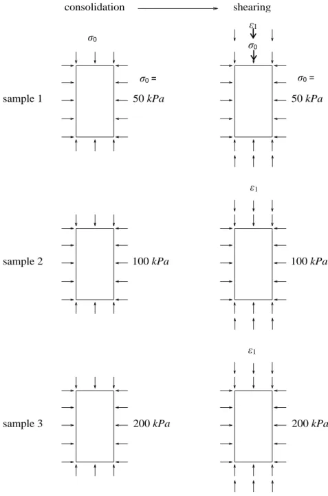
3.3.1 Experimental and numerical test ... 61
3.3.2 Comparison of stress strain response ... 67
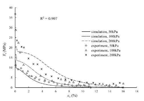
3.3.3 Evolution of tangent modulus ... 72
3.4 Analyses of pressure exponent in undrained condition and the related density ... 73
3.4.1 Influence of pressure exponent in undrained condition ... 73
3.4.2 Effect of density on the influence of pressure exponent ... 78
3.5 Analyses of pressure exponent in drained condition... 79
3.6 Modified SANISAND model ... 81
3.7 Conclusions... 87
Chapter 4 – Second-order work analyses ... 89
4.1 Formulation of W2 ... 89
4.2 Stabilities analysis of axisymmetric model... 93
4.3 Stabilities analysis of slope model ... 96
4.3.1 Slope model established ... 96
4.3.2 Dry conditions ... 99
4.3.3 Partly saturated condition ... 114
4.4 Second-order work results ... 127
4.4.1 Stability modeling with W2n ... 127
4.4.2 Influence of pressure exponent on W2n ... 130
4.5 Conclusion ... 132
Chapter 5 – General conclusion and perspectives ... 134
5.1 General conclusion ... 134
5.2 Perspectives ... 135
Appendix A — ... 137
Appendix B — New model ... 141
Appendix C — ... 147
Modified SANISAND model ... 147
List of Figures
Figure 2.1 Hardening hyperbolic relation for 2 values of coefficient Bp (with φE =30°, φE =35°) (BAR
98) ... 22
Figure 2.2 Experimental limit surfaces for Hostun sand, modified from (LAN 88) ... 24
Figure 2.3 a) representation of the principal stress space, b) deviatoric plane (BAR 98) ... 26
Figure 2.4 Limit surface for Mohr-Coulomb criterion in the deviatoric plane for φ =35° (BAR 98) ... 27
Figure 2.5 Limit surface for Drucker Prager criterion in the deviatoric plane for φ =35° (BAR 98) ... 27
Figure 2.6 φC vs φE for Drucker Prager criterion (BAR 98) ... 29
Figure 2.7 Limit surface for Van Eekelen criterion in the deviatoric plane for φ = 35° (BAR 98) ... 32
Figure 2.8 Limit surfaces for Mohr Coulomb, Drucker Prager and Van Eekelen criteria in the deviatoric plane for different friction angle value: a) φ=5°, b) φ=20°, c) φ=35°, d) φ=45° (BAR 98) ... 35
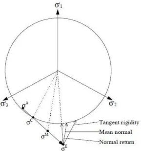
Figure 2.9 Evaluation of the trial stress state at point E ... 36
Figure 2.10 Choice of the normal: comparison between three possible directions for a Von Mises type criterion (BAR 98) ... 37
Figure 2.11 Fully implicit scheme: stress space representation for perfect plasticity (BAR 98) ... 38
Figure 2.12 Implicit backward Euler integration algorithm implemented in the elastoplastic constitutive law PLASOL (BAR 98) ... 40
Figure 2.13 Model surfaces in q-p triaxial stress space (MAN 97; DAF 04) ... 53
Figure 3.1 Mesh and boundary conditions of axisymmetric homogeneous triaxial test sample ... 61
Figure 3.2 Flow chart of experimental triaxial test ... 63
Figure 3.3 Experimental relationship results of stresses and strains ... 64
Figure 3.4 Comparison between experimental and numerical results obtained using new model ... 66
Figure 3.5 Comparison results between experimental tests and numerical simulations ... 68
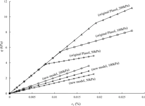
Figure 3.6 Comparison results between new model and original Plasol model ... 70
Figure 3.7 Comparison results between new model and original Plasol model within very small strain71 Figure 3.8 Evolution of tangent modulus for experimental tests and simulations ... 73
Figure 3.10 Evolution of ratios of shear stress to mean effective pressure ... 77
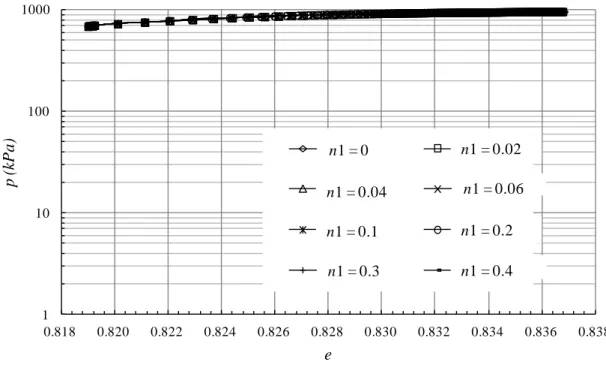
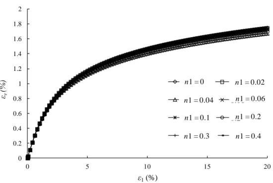
Figure 3.11 Void ratio versus mean effective pressure in drained triaxial simulation ... 80
Figure 3.12 Stress-strain responses in drained simulation for different pressure exponents ... 81
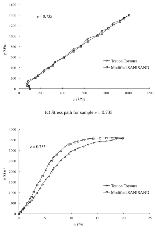
Figure 3.13 Simulation by Modified SANISAND versus experiments in undrained triaxial tests on samples of Toyoura sands (LAS 10; VER 96) ... 84
Figure 3.14 Comparison results between new model and modified SANISAND model ... 87
Figure 4.1 Solutions of equation: 𝛌𝟏𝐗𝟐 + 𝛌𝟐𝐘𝟐 + 𝛌𝟑𝐙𝟐 = 𝟎, which is a reduction of the quadric 𝐭𝐝𝛔 𝐍𝐬 𝐝𝛔 = 𝟎 (PRU 16)... 91
Figure 4.2 Limit of the bifurcation domain plotted in deviatoric plane for constitutive models of Darve, compared with plastic limit of Morh-Coulomb (PRU 09) ... 92
Figure 4.3 Response of undrained triaxial test simulation ... 94
Figure 4.4 Change of W2n along the undrained triaxial test simulation ... 96
Figure 4.5 Geometric size of slope model ... 97
Figure 4.6 Boundary and loading conditions of slope ... 98
Figure 4.7 Mesh graph of slope model ... 100
Figure 4.8 Slope simulation cases for drained condition ... 101
Figure 4.9 Simulation results at the final step for drained case 1 without concentrated pressure (n1 = 0) ... 103
Figure 4.10 Simulation results at the final step for drained case 1 without concentrated pressure (n1 = 0.1) ... 104
Figure 4.11 Simulation results at the final step for drained case 1 without concentrated pressure (n1 = 0.2) ... 105
Figure 4.12 Simulation results at the final step for drained case 1 without concentrated pressure (n1 = 0.3) ... 106
Figure 4.13 Simulation results at the final step for drained case 1 without concentrated pressure (n1 = 0.4) ... 107
Figure 4.14 Evolution of normalized second-order work and mean pressure in drained case 1 ... 108
Figure 4.15 Simulation results at the final step for drained case 2 with concentrated pressure (n1 = 0)110 Figure 4.16 Simulation results at the final step for drained case 2 with concentrated pressure (n1 = 0.2) ... 111
Figure 4.17 Simulation results at the final step for drained case 2 with concentrated pressure (n1 = 0.4)
...112
Figure 4.18 Evolution of normalized second-order work and mean load in drained case 2 ...113
Figure 4.19 Geometric size of slope for undrained test ...115
Figure 4.20 Mesh graph of slope for undrained situation ...115
Figure 4.21 Simulation results at the final step under undrained condition (n1 = 0) ...117
Figure 4.22 Simulation results at the final step under undrained condition (n1 = 0.02) ...118
Figure 4.23 Simulation results at the final step under undrained condition (n1 = 0.04) ...119
Figure 4.24 Simulation results at the final step under undrained condition (n1 = 0.06) ... 120
Figure 4.25 Simulation results at the final step under undrained condition (n1 = 0.08) ... 121
Figure 4.26 Simulation results at the final step under undrained condition (n1 = 0.1) ... 122
Figure 4.27 Simulation results at the final step under undrained condition (n1 = 0.2) ... 123
Figure 4.28 Simulation results at the final step under undrained condition (n1 = 0.3) ... 124
Figure 4.29 Simulation results at the final step under undrained condition (n1 = 0.4) ... 125
Figure 4.30 Maximum stresses at the end of loading process for different n1 ... 126
Figure 4.31 Evolution of normalized second-order work at node 3 in undrained condition ... 127
Figure 4.32 Evolution of integrated second-order work in undrained case with n1 = 0 ... 128
Figure 4.33 Evolution of W2n with respect to the pressure imposed with n1 = 0 ... 129
Figure 4.34 Evolution of W2n in undrained slope simulation ... 130
List of Tables
Table 2.1 Modified SANISAND model in triaxial space ... 51
Table 3.1 Mechanical properties of experimental samples ... 63
Table 3.2 Optimal parameters determined in original Plasol model ... 66
Table 3.3 Simulation difference between experiments (EXP), original Plasol model (ORI) model and new model (NEW) ... 69
Table 3.4 Parameters adopted in undrained test simulation for sample 1 and sample 2 ... 74
Table 3.5 Physical properties of Toyoura sand (VER 96) ... 82
Table 3.6 Simulation parameters adopted in modified model (VER 96) ... 82
Table 3.7 Optimal parameters of Toyoura sands sample for new model ... 85
Table 4.1 Actual mechanics parameters of slope model ... 98
Notations
Latin symbols
a, b, n Parameters related with yield function in Chapter 2
Bp , Bc Hardening coefficients of the Plasol model
c Cohesion
cijkl Compliance matrix component
𝐷𝑖𝑗𝑘𝑙𝑒 , 𝐷𝑖𝑗𝑘𝑙 𝑝
Constitutive elastic tensor component, constitutive plastic tensor component
D(ijkl), D(ij) Jacobian matrix (incremental stiffness matrix) component
dijkl Stiffness matrix component
dQ, dF Global nodal incremental displacement and force
E Young’s modulus
E’ Complementary energy (Gibbs free energy)
eij Deviator of strain tensor component
e Void ratio
F Strain energy (Helmholtz free energy)
f Yield surface
G, G0 Shear modulus, small strain shear modulus
g (1) Plastic potential, (2) shear stiffness factor
Iσ First stress invariant
𝐼𝐼𝜎̂ Second deviatoric stress invariant
Ⅲ
𝜎̂ Third deviatoric stress invariant
J Coupling modulus
K Bulk modulus
K Global consistent tangent matrix
k (1) Over-consolidation ratio exponent (also with * superscript), (2) bulk stiffness
factor
k0 Permeability
m, m’, k’ Parameters as function of cohesion , friction angle or dilatancy angle
n1 Pressure exponent (also with * superscript)
N Rate-independent constitutive operator
Ns Symmetric part of N
p, p’ Effective mean pressure
pa Atmospheric pressure
q Deviator stress (invariant)
R Over-consolidation ratio in terms of mean effective stress (also with subscript)
r, rC, rE Reduced radius, reduced radius in compression, in extension
S Dimensionless stiffness factor (also with * superscript and η subscript)
Sij Anisotropic stiffness factor
sij Deviator of effective stress tensor component
Val Scalar related with equivalent plastic strain
W2,W2n Global second-order work, integrated second-order work
w2, w2n Local second-order work, normalized second-order work
Xi Position vector
Greek letters
∆() Increment
β Lode angle
δij Kronecker tensor (unit tensor)
𝜀𝑖𝑗 Strain tensor
𝜀𝑣 Volumetric strain
𝜀𝑣∗ Modified volumetric strain
𝜀𝑣0 Function of strains
𝜀𝑠 Shear strain
𝜀̇𝑖𝑗, 𝜀̇𝑖𝑗𝑒, 𝜀̇𝑖𝑗 𝑝
Components of strain rate, elastic strain rate and plastic strain rate
𝜀𝑒𝑞𝑝 Equivalent plastic strain
φC Friction angle under triaxial compression path
φE Friction angle under triaxial extension path
η Triaxial stress ratio
κ Internal variables
κ’ Slope of swelling line in a consolidation plot
𝜆 Lame’s first parameter
𝜆̇ Plastic multiplier
μ Lame’s second parameter
ν Poisson’s ratio
ρ Density
𝜎𝑖𝑗, 𝜎̇𝑖𝑗 Components of stress tensor (effective) and stress rate
𝜎𝑁 Normal stress
𝜎̂, 𝜎̂𝑖𝑗 Deviatoric stress tensor, deviatoric stress tensor component
σ1*, σ2* , σ3* Projection of the principal stress on the deviatoric plane
σ0 Confining pressure
τ Tangential stress
General introduction
Nowadays, the constitutive modeling work of the geomaterials has been causing various
geotechnical researchers’ attention for more than 50 years, as well as the detecting and definition
problems of failure. The granular material which is a representative material of general geomaterials
always shows a non-linear stress and strain response in both elastic part and plastic part. Therefore,
when numerically simulating the actual behavior of granular materials, the non-linearization should be
taken into account. Besides, another important fact that natural soils show characteristics of
cross-anisotropy (or transverse isotropy) requires also attention (CAS 17). Anisotropy could be
divided into two parts, namely inherent anisotropy and induced anisotropy depending on the
formation condition, which is due to the process of natural deposition and later disturbance
respectively (ART 72; ODA 72c). Also, the anisotropy could also be composed into fabric anisotropy,
stress or stiffness anisotropy and permeability anisotropy (KUH 15) from the manifestations aspect
which are closely related with the external loading. Therefore, this research work, our main purpose
focuses on the stress-induced anisotropy and its influence on the response of stress and strain.
In order to simulate the appropriate behavior of granular materials, various authors present some
anisotropic elastoplastic models. For normally consolidated or lightly overconsolidated soil, an even
small increase of stresses is likely to cause yielding. It is also easily concluded that the plastic
deformation is likely to dominate for most problems of practical interest, while the elastic strain is
relatively unimportant (WHE 03). At the meantime, when simulating this kind of behavior, the
elasticity part in elastoplastic model has an influence on the response of stress and strain (CHA 05). In
that case, the feature of anisotropy in elastic domain in the whole process of deformation is way
important even though some elastoplastic models neglect the anisotropic characteristic in the elastic
part for the reason of simplification (SCH 68; ROS 68; WRO 80). Besides, the hyperelastic
formulations which are energy conservative and thermodynamically consistent present the feature that
the elastic behavior can be derived from a relative potential energy function (HOU 00; EIN 04; GAJ
08). That means that a theoretical relation between stress and strain can be derived from this kind of
formulation. Furthermore, another point needs to be focused on is that the stiffness matrix derived
05). Moreover, the induced anisotropy which occurs when non-zero value of off diagonal components
exist in the stiffness matrix shows a good relation with the natural response of granular materials.
The problem of observation and definition of failure of soil has also been a hot issue for decades.
The complex properties of granular materials determine that the analysis work is hard and elusive for both theoretical and physical definition of failure. Despite the earliest but outdated definition that
failure occurs accompanied with the existence of a limit stress state which is impossible to exceed for
any possible monotonous loading path, the basic but classical Lyapunov’s definition of stability shows
a different and contradictory theory with the limit stress state theory mentioned before (LYA 07). Moreover, Lyapunov’s definition clearly states that the materials instabilities can be expected in elastoplastic media. But Lyapunov’s definition has limitation because it does not provide a well defined mathematical equation for a proper media. Thus the Hill’s condition of stability is taken into
account (HIL 58). Hill states that a stress strain state is unstable if one loading direction which can be
pursed in an infinitesimal manner exists and there is no external energy input in this direction. It
means that the deformation could proceed itself without any input external loading or energy. Basing
on Hill’s theory, the equation of second-order work which is the product of incremental strain and
incremental stress is established and used for determine the existence of specific failure. According to
Daouadji’s synthesis work (DAO 10), the equations of bifurcation domain in the stress space and of
cones of unstable loading directions with proper control parameters are established from experimental,
theoretical and numerical points. It is also far important that an essential feature of failure can be the
outburst of kinetic energy accompanied with the drastically increased strains and decreased stresses.
Furthermore, three necessary and sufficient conditions for an effective failure are proposed, namely:
(1) the stress state within bifurcation domain, (2) the loading direction within cones of unstable
directions, and (3) the proper parameters set in right place (LAO 02; PRU 009; NIC 09).
In order to apply the second-order work criterion basing on an appropriate constitutive relation,
several works should be done in advance, and these works will be shown in the following Chapters.
In Chapter one, the literature research about anisotropy is firstly presented, which includes the
different components of inherent and induced anisotropy in the way of generation, and the fabric and
stress/stiffness anisotropy. As well, some latest anisotropic elastoplastic models are shown. Moreover,
a hyperelastic formulation which is closely relevant with actual engineering situation is introduced
detailed.
In the second Chapter, an elastoplastic constitutive model ‘Plasol’ which contains an implicit
backward Euler integration algorithm is firstly presented. Much emphasis is put on the fact that this
Plasol model involves a general yield criterion which could be anyone of classical failure criterion,
such as Mohr-Coulomb, or Drücker Prager and so on. Secondly, a hyperelastic strain energy function
which is thermodynamically consistent is taking into account. The elastic strain energy is expressed in
terms of strain invariants so that related stress invariants as a function of the strains can be derived
from this function, as well as the incremental stiffness matrix. Thirdly, the combination and
replacement work of Plasol model and the elastic stress strain relation mentioned above is
implemented. Thus a new constitutive relation which is much appropriate theoretically for the
behavior of non-associated granular materials is established. Last, another constitutive model which
also considers the anisotropic elasticity will be shown in detail.
The works concerning numerical simulations will be described in the following Chapter 3. First
of all, the equations of models mentioned before, including the original Plasol model, Modified
SANISAND model and the new model we proposed, will be written in the User-Defined Material
(abbreviated as ‘UMAT’) tool in FORTRAN which could be used as external model in ABAQUS
simulation. Later, a simplified but representative axisymmetric Abaqus model will be built and run
with these models. After, the comparison results between the simulations and experimental data will
be shown, as well as the relevant evolution of tangent modulus. Then, the undrained triaxial tests will
be implemented to analyze the influence of parameter namely pressure exponent, and the effect of
different densities of samples with different Young’s moduli and Poisson’s ratios will be taken into
account to test on the influence of pressure exponent. At the end, the simulation by modified
SANISAND model will be compared with new model.
In the fourth Chapter, the second-order work criterion will be adopted with this new model
written into the Umat format. The use of global or integrated second-order work criterion used as a
safety factor will be discussed.
Chapter 1 – Literature review
1.1 Research on anisotropy
1.1.1 Inherent and induced anisotropy
In materials science, anisotropy is a material’s directional dependence of a physical property. It is
a critical consideration for materials selection in engineering applications. Tensor descriptions of
material properties can be used to determine the directional dependence of that property. In other
words, the diverse directional dependence of internal structure determines the anisotropic physical
property, as well as the application in engineering problems.
Anisotropy can be composed by two forms: inherent anisotropy and stress induced anisotropy.
The former one is formed because of preferred particles and contacts orientations that develop in the
process of deposition, while the latter one is due to the displacement or the loaded stress during later
activities (ART 72; ODA 72c). According to Arthur and Menzies (ART 72), the inherent anisotropy of
non-cohesive granular materials is described. Samples are set up in different directions of deposition
referring to the sample axes and then loaded in principal stress directions. It is concluded that inherent
anisotropy can emerge in the direction corresponding to strength and pre-failure stress-strain
anisotropy. Furthermore, the coincidence of principal stress axes and direction of strain increment is
shown up, as well as the anisotropic effects on stress-strain response. Oda shows that the fabric
reconstruction of initial fabric is continuous and is caused mostly by the sliding along unstable
contacts between the neighboring particles and partly by the rotation of particle during the process of
axial strain increment. Note that a material’s fabric describes the spatial and geometric configuration
of all the elements that make it up.
Arthur et al. (ART 77) also publishes a work about the pre-failure induced anisotropy in dense
granular media. After the plane strain test with controlled changes of principal stress directions, it is
found that the induced anisotropy has less influence on the angle of shearing resistance but large
effect on the secant modulus on reloading after a principal stress rotation. Moreover, the different
directions between the present axes of induced anisotropy and previous axes leads to slight and
This theory is also mentioned and used as fundament by later researchers. Hu et al. (HU 10)
emphasize the fact that the anisotropy of structure of granular materials can influence the response of
stress and strain, and its feature of two kinds of components, i.e. inherent and induced anisotropy. In
their paper, the fabric tensor is used to explicitly present the interactions between individual particles,
and its eigenvalues can be treated as a measure of the fabric anisotropy, so does the coordination
number to the packing density of material. Here, the coordination number is described as the average
of the contacts of all grains of an assembly. The Discrete Element Method (DEM) in two-dimensional
is used to simulate the evolution of fabric in cyclic loading condition. It is found that the inherent
anisotropy decreases in the process of isotropic consolidation, but increases in the process of
anisotropic consolidation. The anisotropy which is induced by the loading cyclic stress path has a
dependency on maximum and minimum values of cyclic loadings. Furthermore, the ratio of normal to
shear springs stiffnesses can influence the development of anisotropy, with the fact that higher value
of this ratios corresponding to lower degree of anisotropy induced by anisotropic consolidation.
Induced anisotropy could also be decomposed into fabric anisotropy, stress (or stiffness)
anisotropy and permeability anisotropy (KUH 15). According to Kuhn et al., the anisotropies of
granular particles (fabric) and of materials’ strength, stiffness and permeability are induced by the
external loading on samples. For fabric anisotropy measurements, there are four categories which are
preferred orientation of particle, particle surface, normal contacts and void space can be developed. It
is found that the measures of particle’s orientation are the most representative one to loading. For
stiffness anisotropy, it is concluded that this kind of stiffness increases along the initial compressive
loading direction and reduces along the extension direction. Furthermore, it is closely matched with a
special measure of contact fabric. For permeability anisotropy, the results that the permeability is
negatively linked with directional mean free path and is positively linked with pore width show that
the induced permeability anisotropy is caused by the changes in the direction of directional hydraulic
radius.
1.1.2 Fabric and stress/stiffness anisotropy
For geotechnical materials, especially natural soil, the response of stress and strain shows a
phenomenological or micro-mechanical-based. When simulating this kind of behavior, the elasticity
part in elastoplastic model has an influence on the response of stress and strain (CHA 05). According
to Chang and Hicher, the inter-particle stiffness is closely related to inter-particle elastic constants and
proportional to the mean particle size. This stiffness can directly affect the response of stress and
strain under an externally applied stress for an assembly of particles. In this paper, an elastoplastic
model which is a combination of Hertz-Mindlin’s elastic law and Mohr-Coulomb’s plastic law is
established. They also conclude that the anisotropic samples which are placed in different loading
directions show the model’s qualification and consideration of the influence of inherent anisotropy on
the behavior of stress and strain in drained triaxial loading test.
Oda et al. (ODA 85) presented that three main factors affecting and quantifying the fabric
anisotropy which are the: (1) distribution of normal contacts; (2) shape of non-spherical particles; and
(3) shape of associated voids. In their paper, a basis of biaxial compression tests performed on
two-dimensional assemblies is used to define the second-rank fabric tensor which is representative of
the corresponding anisotropy. It is found that the direction of principal axes of fabric tensor changes
gradually approaching to the principal axes of stress tensor in the process of monotonic loading.
Moreover, the generation of particle contacts along the maximum principal compression are closely
linked with the order of column-like loading paths along the same direction, and these new contacts
result in the stress-induced anisotropy and seem to be a contributing factor to the post-peak failure.
Li and Dafalias (LI 12) proved that the anisotropic critical state theory which accounts for the
role of anisotropic fabric of the classical critical state theory is appropriate for large deformations. A
fabric tensor is taken into account during the studies of micromechanics and experiments, and a scalar
fabric anisotropy variable which is an evolving fabric tensor in the direction of loading is also
proposed. It is shown that, when this variable reaches its critical state value, the dilatancy state line in
the void ratio – pressure plane is coincident with the classical critical state line, and the dilatancy state
parameter evaluating the contracting or dilating trends of current state changes toward to the value of
dilatancy angle. Moreover, the feature of static liquefaction occurs when the dilatancy state parameter
equals to zero and stress ratio reaches its critical value.
Another related factor that has to be considered is its cross-anisotropy (or transverse isotropy)
due to the geological processes, which leads to a more complicated and unpredictable relationship of
of anisotropy in fabric because of the shape of clay platelets, deposition process and one-dimensional
consolidation, and this behavior can be called as cross-anisotropy or transversely isotropy. A new
constitutive model includes the anisotropic behavior of elastic and plastic features and incorporates
the stress-dependent cross-anisotropic elastic behavior using three independent elastic parameters and
one additional variable, namely the ratio of horizontal and vertical stiffness. The evolution of elastic
anisotropy is not considered within this new model, but the noticeable variation of elastic anisotropy
can be caused within a large deformation condition, which induces a more complex relationship
between strain and stress.
Zdravkovic et al. (ZDR 02) state that neglecting this anisotropy of natural soil behavior can
induce high inaccuracy during the predicting of stress-strain response. When designing and
calculating the safety factor of embankment, the traditional way is often based on a limit equilibrium
approach with a consideration of isotropic materials. However, the natural soil always shows the
behavior of anisotropy in both stiffness and strength, so that the old practice would be inaccurate and
uneconomic even the empirical factors are introduced into conventional design procedures.
Other studies have been done about the influence of anisotropy on the stress-strain in different
situations. Toyota et al. (TOY 14) investigated the stability of slopes which were affected by the
anisotropy of shear strength induced by K0 consolidation and swelling in cohesive soils. Due to the
reason that shear direction changes at each sliding points, the strength anisotropy should be taken into
account in the process of stability analyses. Therefore, in this paper the undrained torsional shear tests
and two-dimensional plane strain tests conducted on samples which are consolidated and swollen in
different directions are implemented to assess the influence of anisotropy of shear strength. Results
show that the anisotropy of undrained shear strength closely corresponding to the difference between
consolidation and shearing in terms of directions and stress condition. Furthermore, the slope stability
analyses also need take the anisotropy of undrained shear strength into account.
Additionally, the influence of anisotropy on the failure with localization pattern and the limit
loading capacity of geostructure is investigated by Chang et al. (CHA 14). For this purpose, an
extended Drücker Prager yield criterion is developed for this kind of transversely isotropic
geomaterials. After simulating with Finite Element Method, the results show that the localization
pattern and the critical bearing capacity of geostructure are corresponding closely to the principal
The existence and the level of anisotropy occurring in particulate materials which have nearly
spherical aggregates have been shown within the work of Oboudi et al. (OBO 16). To this aim, both
experimental test and theoretical support are contained in this study. The former is about the
performance of series of tests at different sample orientations, while the latter is about the plasticity
formulation based on a critical plane approach. The results present that the proposed framework can
account for the various performance of load-induced anisotropy.
1.1.3 Anisotropic elastoplastic models
Before introducing anisotropic elastoplastic models, the general elastoplastic models have been
accepted for decades and adopted until now. For example, the elastoplastic Plasol (BAR 98) model
which contains a linear elastic part and a plastic part is a general constitutive model for granular
materials which will be show detailedly in the Chapter 2. In this Section, however, the anisotropic
elastoplastic models are focused on.
Several authors have done extensive experimental testing and proposed relevant elastoplastic soil
models for modeling the mechanical behavior of natural soils. Dafalias (DAF 86) presents the fact that
the isotropic constitutive model is inappropriate for modeling the behavior of stress and strain of soil
within the framework of elastoplasticity. Then an evolution law with yield surface accompanying
anisotropic features such as rotational hardening has been postulated basing on the provided
expression of a rotated and distorted ellipse as the yield surface. These constitutive equations equip a
significant feature of simplicity, as well as the successful comparison with experimental data.
Whittle and Kavvadas (KAV 94) proposed an effective stress model for clays normally and
moderately and over-consolidated. Three components are comprised in this model which are: the
elastoplastic model for clay normally consolidated and including the behavior of anisotropy and strain
softening; the equations describing the nonlinearity of small strain and characterizing the hysteretic
response in the process of loading and unloading; and the surface plasticity of boundary for
irrecoverable, anisotropic features of overconsolidated clays. Furthermore, the complexity of model
can be controlled by using specific parameters which are obtained from few standardized soil tests.
However, some of these models assume that the elastic part of the model is isotropic due to the
known that the natural soils exhibit anisotropy of elastic behavior (GRA 83; WHE 03). Graham and
Houlsby describe the anisotropic behavior of natural clays because of the mode of deposition. Five
elastic parameters which could reduce to three in the situation of triaxial tests are also proposed to
describe the transverse isotropy. For example, in these required parameters, the bulk modulus, shear
modulus, and cross modulus are easily identified and can be used to express the behavior of
anisotropic soil between strain and stress, i.e., mean stress and shear strain, shear stress and
volumetric strain specifically. The result of this anisotropic model is compared with true triaxial tests
and results show that the clay is approximately 1.8 times stiffer along the horizontal direction than
vertical direction which is a quite strongly anisotropic.
According to Wheeler et al. (WHE 03), an anisotropic elastoplastic model is presented on the
basis of experimental data for shape of yield curve and relationship describing the influence of plastic
straining on yield curve inclination. This model is called S-CLAY1 and incorporates a rotational
component of hardening in the reason of influence of plastic anisotropy. This rotational hardening law
contains the dependence on plastic shear and volumetric strain increment and is also validated by
conventional drained triaxial tests on clay. The simulation results of new model are compared with
experimental data and proved improving the performance of the Modified Cam Clay model (ROS 68).
However, it also equips a shortcoming, which is that it would under-predict the post yield volumetric
strain in the case of high values of stress ratio. This shortcoming could be made up by taking the
bonding and destruction into account which has been shown in an extended version (KAE 05) of this
model.
Schädlich and Schweiger (SCH 13) check the effect of anisotropic elasticity on the deformation
behavior of deep excavations and strip footings in means of a constitutive model. A model which
incorporates the feature of taking the anisotropic elasticity into account in the range of small strain is
proposed and aimed to solve two simple benchmark problems mentioned above. The studies show
that under the condition of relatively low displacement and strains, the influence of small strain
stiffness anisotropy is more significant than the case under higher strains conditions. It is also found
that this kind of stiffness anisotropy can be approximated as the average of axial stiffnesses.
However, their model is limited in a very small range of strains and can’t be regarded as a full constitutive model because it doesn’t consider stress-dependent stiffness and plastic strains. Based on
Castro and Sivasithamparam (CAS 17), avoids this problem and contains a yield surface function and
stress-dependent stiffness. Based on the fact that S-CLAY1 takes the initial and plastic strain induced
anisotropy into account, its extension model, i.e., S-CLAY1S also considers additionally the case of
inter-particle bonding and degradation of bonds. After comparing results of these two models and
isotropic Modified Cam Clay with the obtained field data, it is shown that the anisotropy is
importantly and necessarily taken into account, whereas the influence of destructuration seems to be
implicit on the predicted deformations. This model also had a good agreement with the field
measurements, according to the work of Yildiz et al. (YIL 09) on embankment test.
The extended model based on S-CLAY1S, is proposed for situation of cross-anisotropy (CAS 17)
which also shows anisotropy behavior both of elastic and plastic nature as well as the
stress-independent cross-anisotropic elastic behavior. Note that the cross-anisotropy behavior could be
described with three elastic parameters in this model which have been discussed by Graham and
Houlsby (GRA 83). Only one additional parameter is contained in this new model, i.e., the ratio of
horizontal stiffness to vertical stiffness, which can be easily obtained from conventional experimental
tests. By the model, the initial non-vertical effective stress path can be analytically and easily captured,
and the deviatoric strain in the process of isotropic loading and unloading can be predicted as well.
Another extended model based on S-CLAY1S was proposed by combining the anisotropy and
destructuration using an elasto-viscoplastic model on the natural soft clays (YIN 11). The clays which
equip the strain-rate-dependency were tested at constant strain-rate and creep in one-dimensional and
triaxial conditions. With this model, the result that loading scenarios is necessary to get an accurate
prediction when accounting for anisotropy and / or destructuration was revealed. Also, the fact that
proposed model can successfully reproduced the time-dependent behavior of natural soft clays can be
obtained by the comparisons between predicted and measured results.
1.2 Hyperelastic formulation
Before introducing the hyperelastic formulation in this Section, the definition of elasticity,
hyperelasticity and hypoelasticity should be well described in detailed. Elasticity in materials science
is the ability of a material body to resist a distorting influence and to return to its original size and
original shape and size after the removal of influence or force. Hyperelasticity or hyperelastic material
is a type of constitutive model for ideally elastic material for which the stress-strain relationship
derives from a strain energy density function. This type of material is a special case of simple elastic
material. Note that the hyperelasticity equips an integrable expression because it is derived from a
potential function, and it shows a conservative elastic response. Hypoelasticity or a hypoelastic
material is an elastic material that has a constitutive model independent of finite strain measures
except in the linearized case. Hypoelastic material models are distinct from hyperelastic material
models (or standard elasticity models) in that, except under special circumstances, they cannot be
derived from a strain energy density function. This kind of elasticity shows non-conservative elastic
response.
An approach could be used here for the non-linear elastic response of stress and strain (HOU 85;
HUE 92; BOR 97) which is related to hyperelasticity. According to Houlsby (HOU 85), the use of a
shear modulus proportional to the mean effective stress is justified by measurement modeling the
elastic behavior. It is also shown that this measurement has a shortcoming that it induces a
non-conservative elastic behavior and is inappropriate for the case of cyclic loading. Thus, a
theoretical approach using the pressure dependency shear modulus is proposed and several
experimental evidences for supporting this approach are discussed. Moreover, Hueckel et al (HUE 92)
proved an approach that the shear modulus is not only depending on the mean pressure but also on the
over-consolidation ratio. Later, a stored energy functions including two invariants and describing
hyperelastic characteristics is coupled with a critical state plasticity model by Borja et al. (BOR 97).
The pressure dependency elastic shear modulus is included in the energy function and makes the
function satisfying elastic behavior for any loading path and being energy conservative. After
assessing the pressure dependency of shear modulus within elastic and plastic response for undrained
elastic responses, this hyperelastic model shows a fundamentally accuracy simulation of elastic
behavior.
Unlike constitutive models with hypoelastic formulation, the hyperelastic formulations present
energy conservative behavior (elastic stress or strain can be derived from a potential function) and
thermodynamics consistency (HOU 00; EIN 04; HOU 05; GAJ 08). Houlsby and Purzin (HOU 00)
proposed four energy functions to describe the combinations of stress, strain and temperature, and
irreversible behavior could be described by a dissipation function or a yield function, which is related
to the degenerate case of Legendre transformation. According to Einav et al. (EIN 04), a versatile
energy potential function is firstly presented within the framework of an energy conservative or
non-conservative elasticity and a plasticity model. The fact that the stiffness of soil depends on the
pressure is also shown in this work. The combination of this energy potential and hyperplastic
constitutive relation allows for the relevant model to obey the Law of Energy Conservation for both
elastic and plastic parts of soil behavior. Except that, two very important features are that this model
can automatically show a stress-induced cross-anisotropy of elastic component, and that a dilatancy
term can arise because of the pressure dependency shear modulus. The model with these features,
which are neglected by conventional hypoelastic-plastic model, shows a significant accuracy on the
prediction of undrained behaviors of overconsolidated clays. Houlsby et al. (HOU 05) also present a
hyperelastic formulation which shows the non-linear elastic behavior and the dependency of elastic
modulus on mean effective stress. Furthermore, the elastic model which is derived from this
hyperelastic formulation allows the elastic modulus being a function of effective mean stress, and
satisfies the thermodynamic acceptability. Similarly, Gajo and Bigoni (GAJ 08) also present a
formulation based on hyperelasticity after showing the experimental evidence that cohesive and
granular materials contain an elastic range in which the elasticity is non-linear and anisotropic. This
formulation is established within the framework of elastoplastic coupling via the new proposal of
elastic potentials and the combination of non-linear elasticity and dependency of fabric tensor on
plastic strain. Combining the formulation in the proposed constitutive framework, the simulation
results show a very accurate fitting degree on the evolution of elastic behavior with the existing
experimental data.
1.3 Second-order work criterion
For modeling the behavior of geo-materials, several constitutive models are proposed and
mentioned above. However, the observation and definition of the failure of sample is also important,
so do the tools for detecting failure.
The theoretical and physical definition of failure in solid and its analysis is hard and elusive to
way to detect the failure behavior, as well as its defining criterions. In fact, there is a version of failure
definition at initial time that failure occurs accompanied with the existence of special limit stress
states which are impossible to exceed for any possible monotonous loading path. This physical
definition shows that large deformation, cracks, or fragmentation will suddenly occur if any tiny
additional loading is loaded at such limit stress state. This change of materials state is called roughly ‘failure’.
Around the initial definition above, two typical classes of failure modes due to the instabilities
can be found in either geometric or materials, which could be expressed in column buckling, or
constitutive behavior respectively based on the observations of experiments tests. Within the domain
of instability, two popular criteria have emerged. The first criterion is about the vanishing of
determinant value of the acoustic tensor (RUD 75) which is accompanied with the emergence of
plastic strain localization, whereas the second one refers to the vanishing of the determinant of the
whole constitutive tensor which involves the signals failure at plastic limit condition.
For the associated materials, such as metal materials which follow the associative flow rule, these
two criteria mentioned above coincide because of the symmetry feature of the elasto-plastic tensor.
However, the geomaterials are widely known as non-associated materials because of the
non-symmetry of the elasto-plastic tensor. Therefore, based on the evidence of much laboratory
experiments, the localization criterion can be met before the plastic limit criterion for particularly
dense sands or overconsolidated clays (VAR 95). However, for the fact that the stress controlled
undrained triaxial test on very loose sands show a performance of different type of failure, this
different mode of failure occurring at the peak of deviatoric stress which is not described before is
named as ‘diffuse failure’ (KHO 06) to distinguish it from the localized one (NIC 10; DAO 2010; JRA
12).
The problems of bifurcation occur due to the loss of uniqueness of the basic governing equations’
solution which is caused by the instability of materials. Therefore, it is quite necessary to propose the
bifurcation theory being a general framework when analyzing all kinds of failure. Bifurcation happens
at the time that the system state changes suddenly following with one of the at least two possibilities,
which could be either stable or unstable state, under the condition of continuous variations of state
variables. For example, with the condition of proper loading, failure can happen with a state
exponential growth of strains (DAR 07; NIC 09; SIB 09). This kind of phenomenon is closely related
with the experimental phenomenon of failure. Furthermore, one of the bifurcated states’
characteristics refers to the fact that failure will happen with small additional perturbations in the
system. Based on this kind of property, failure can be also considered as an instability phenomenon in
the Lyapunov’s definition of stability (LYA 07) which will be described below. As a conclusion, any
tiny additional loading at a given bifurcation state on the curve of stress and strain will result in an
infinitely large responses if proper control variables are applied (direction of loading and mix loading
conditions).
For non-associated materials, which relate to the non-symmetry of the elastoplastic tensor, the
elastoplastic theory considering the bifurcation criteria precede the plastic limit criterion which can be
represented precisely by the zero determinant value of product of elastoplastic matrix and unit matrix
(BIG 91). Different bifurcation criteria exist in the literature which is relating to different modes of
failure. Concerning the shear band formation by plastic strain localizations, Rice’s criterion (RIC 76)
is based on the description that the earliest shear band in normal direction corresponds to the
vanishing values of the so-called ‘acoustic tensor’. However, this phenomenon occurs before the
plastic limit criterion is met for non-associated materials, and this has been demonstrated and verified
in experimental tests on dense sand (DES 90). The plastic strain localization refers to the bifurcated
strain mode from a diffuse one to a strictly discontinuous one. This kind of bifurcation can be called
as ‘discontinuous bifurcation’ or localized mode of bifurcation.
As an opposition of discontinuous bifurcation, the ‘continuous bifurcation’ also refers to a failure
mode but which does not contain strain localization behaviors. Like we present before, this diffuse
failure mode is subjected to a bifurcation with the vanishing constitutive uniqueness at the bifurcation
point. According to Nova’s theory (NOV 94), different loading control model can lead to different
response paths at the bifurcation point, and for certain control modes, the stress state is no more
controllable any longer. This continuous bifurcation, as well as the related diffuse failure mode can be
detected by Hill’s stability condition (HIL 58), which corresponds to the vanishing value of
second-order work for unstable states (DAR 09). Moreover, this vanishing value of second-order work
corresponds to the vanishing value of determinant of the symmetric part of elastoplastic matrix for
non-linear constitutive relation.
condition will be presented in details. Based on Lyapunov’s stability definition re-visited in the field
of solid mechanics, the statement is: “A stress-strain state, for a given material after a given loading
history, is called stable, if for every positive scalar ε, a positive number η(ε) exists such that for all
incremental loading bounded by η, the associated responses remain bounded by ε.” (LAO 02)
According to this definition of stability, all the limit stress states which are mentioned before are
unstable. That means that a very small incremental reverse stress at the limit stress state could induce
a small response, whereas this small incremental additional stress exceeding the limit state can
produce large strain response. Moreover, Lyapunov’s definition clearly states that the materials
instabilities can be expected in elastoplastic media. Taking the fact into account that some limit stress
states are strictly met before the Mohr-Coulomb plastic limit surface, it is possible that instabilities
can occur before the Mohr-Coulomb plastic limit condition is satisfied.
However, Lyapunov’s definition is inappropriate to use in the content of geomaterials. Thus, the
Hill’s condition of stability is taken into account. Hill states that a stress strain state is unstable if one
loading direction which can be pursued in an infinitesimal manner exists and there is no external
energy input in this direction. That means the deformation could proceed itself without any input
external loading or energy. Indeed, in some practice situations, failure happens with external energy
such as the weight or loads on the slope, whereas in some other cases, failure occurs without any
additional energy input from outside such as the landslides, rockfalls and so on. Moreover, based on
Hill’s condition of stability, the stress state is stable if the second-order work which is the product of
incremental strain and incremental stress linked by constitutive relation is strictly positive. This is the
fundamental second-order work criterion, which could be expressed as w2 by the following general
expression.
𝑤2= 𝑑𝜎 ∙ 𝑑𝜀 (1.1)
In this expression, w2 by presents the second-order work, while and σ are ε stress and strain
respectively. The positive value of w2 refers to a stable stress state.
Nicot and Darve (NIC 07) presented the investigation of bifurcation from the view of
micro-mechanics of granular materials. The fact that the vanishing value of second-order work
defined on the macroscopic scale can be viewed as a fundamental role for detecting the occurrence of
bifurcation referring to the loss of sustainability is noted. Also, the relationship between the