HAL Id: tel-01146459
https://tel.archives-ouvertes.fr/tel-01146459
Submitted on 28 Apr 2015
HAL is a multi-disciplinary open access
archive for the deposit and dissemination of sci-entific research documents, whether they are pub-lished or not. The documents may come from teaching and research institutions in France or abroad, or from public or private research centers.
L’archive ouverte pluridisciplinaire HAL, est destinée au dépôt et à la diffusion de documents scientifiques de niveau recherche, publiés ou non, émanant des établissements d’enseignement et de recherche français ou étrangers, des laboratoires publics ou privés.
influence on the interfacial properties of carbon
fiber/epoxy composites
Jing Zhang
To cite this version:
Jing Zhang. Different surface treatments of carbon fibers and their influence on the interfacial prop-erties of carbon fiber/epoxy composites. Materials. Ecole Centrale Paris, 2012. English. �NNT : 2012ECAP0038�. �tel-01146459�
ET MANUFACTURES
« ÉCOLE CENTRALE PARIS »
THÈSE
présentée parJING ZHANG
pour l’obtention duGRADE DE DOCTEUR
Spécialité : Science des matériaux
Laboratoire d’accueil : Laboratoire de Mécanique des Sols, Structures et Matériaux
Soutenue publiquement le 27 septembre 2012
devant le jury composé de :
Michelle SALVIA Maître de Conférences HDR, EC Lyon Rapporteur Mohamed CHEHIMI Directeur de Recherche, ITODYS Paris Rapporteur
Olivier ALLIX Professeur, ENS Cachan Examinateur
Philippe BOMPARD Professeur, EC Paris Examinateur
Jacques CINQUIN Docteur, EADS IW Suresnes Examinateur
Fabien MIOMANDRE Maître de Conférences HDR, ENS Cachan Examinateur
First and foremost I would like to express my sincere gratitude to my supervisor, Mr Jinbo BAI, who offered his constant guidance and encouragement throughout the course of this thesis. This work would not have been possible without his help and support.
I would also like to thank my committee members for their invaluable suggestions and insightful comments. They helped me polish my dissertation.
I am grateful for the financial support of CSC (China Scholarship Council) for this research. I also thank Service de l'Education Ambassade de la République Populaire de Chine en République Françaiset for their support and assistance since the start of this work.
Special thanks are given to Prof. H Daniel Wagner and Dr. Erica Wiesel for their assistance in conducting single fiber fragmentation tests in Weizmann Institute of Science. I would also like to thank Dr. Arnaud Brosseau for FTIR analysis in ENS Cachan and Dr. GEMEINER Pascale for Raman analysis in Laboratoire SPMS.
My thanks are also due to all the staff and students of Laboratoire MSSMat who help me in countless ways during my PhD study, especially, Dr. Delong He, Dr. Hassan Harris, Dr. Hande Yavuz, Dr. Jing Shen, Dr. Weilong Li, Dr. Youqin Lin, Dr. Youssef Magga, Anthony Dichiara, Jérôme Hélary, Jinkai Yuan, Johan Saba, Weikang Li and Farida Djebbari, Françoise Garnier, Sokona Konaté, Sylviane Bourgeois and Gilbert Le-Gal.
Finally, I would like to thank my parents for their emotional support over the past years. I would also like to thank my boyfriend, Pu Xiao. His patience and support have made my PhD much more enjoyable. His love has provided the strength I needed when times were tough.
Acronyms and symbols ... 1
General introduction ... 5
Chapter 1 Introduction ... 9
1.1 Carbon fibers ... 11
1.1.1 Manufacture process ... 11
1.1.2 Structures and properties of carbon fibers ... 13
1.2 Surface treatment and sizing of carbon fibers ... 17
1.2.1 Oxidative surface treatments ... 17
1.2.2 Non-oxidative surface treatments ... 19
1.2.3 Sizing of carbon fibers ... 19
1.3 Carbon fiber-matrix interface ... 21
1.3.1 General introduction to fiber/matrix interface ... 21
1.3.2 Effects of interface on composite performance ... 23
1.3.3 Characterization of interfacial properties of fiber composites ... 25
1.3.4 Improvement of the interfacial adhesion between carbon fiber and matrix 31 1.4 Carbon fiber-reinforced composites ... 40
1.4.1 Manufacture process ... 40
1.4.2 Applications ... 42
1.5 References ... 44
Chapter 2 Sizing of carbon fibers and the influence on the carbon fiber/epoxy matrix interface ... 53 2.1 Introduction ... 55 2.2 Experimental ... 56 2.2.1 Materials ... 56 2.2.2 Sizing process ... 57 2.2.3 Characterization methods... 58
2.2.4 Evaluation of the interfacial shear strength of carbon fiber/epoxy composites... 58
2.3 Results and discussion ... 64
2.3.1 Surface characterization ... 64
2.3.2 Influence of sizing on the carbon fiber/epoxy matrix interface ... 73
2.3.2.1 Determination of carbon fiber tensile strength ... 73
2.3.2.2 Effect of stoichiometry... 75
2.3.2.3 Effect of sizing level ... 80
2.4 Conclusions ... 81
2.5 References ... 83
Chapter 3 Heat treatment of carbon fibers and the effect on the interfacial properties of composites ... 85
3.2 Experimental ... 87
3.2.1 Materials ... 87
3.2.2 Heat treatment of carbon fibers under controlled atmosphere ... 88
3.2.3 Fabrication of unidirectional carbon-fiber reinforced composites ... 88
3.2.4 Characterization methods... 89
3.3 Results and discussion ... 90
3.3.1 Surface properties of heat treated carbon fibers ... 90
3.3.2 Effect of H2/Ar ratio, treatment temperature and time on the interfacial properties... 96
3.3.3 Comparison of the interfacial properties between single-fiber composites and bulk composites ... 101
3.4 Conclusions ... 102
3.5 Acknowledgements ... 103
3.6 References ... 104
Chapter 4 Effect of CNTs on the interfacial properties of CNT-grafted carbon fiber/epoxy composites... 105
4.1 Introduction ... 107
4.2 Experimental ... 108
4.2.1 Materials ... 108
4.2.2 Growth of CNTs on carbon fibers using a continuous CVD method ... 108
4.2.3 Characterization methods... 109
4.3 Results and discussion ... 111
4.3.1 CNT morphologies ... 111
4.3.2 CNT content on the carbon fiber surface ... 114
4.3.3 Raman characterization ... 118
4.3.4 Adhesion of CNT on carbon fiber ... 120
4.3.5 Effect of CNT morphology on the interfacial properties ... 120
4.3.6 Influence of CNT on the electrical conductivity ... 127
4.3.7 Combining use of CNT grafting, heat treatment and sizing ... 129
4.4 Estimate of CNT/carbon fiber joint force ... 131
4.5 Conclusions ... 133
4.6 Acknowledgements ... 134
4.7 References ... 135
Acronyms
AFM atomic force microscopy APO atmospheric plasma oxidation CF carbon fiber
CNT carbon nanotube
CVD chemical vapor deposition DGEBA diglycidyl ether of bisphenol A
FTIR/ATR attenuated total reflectionFourier transform infrared spectroscopy H/CNT HTS40 E23 carbon fibers grown with carbon nanotubes
IFSS interfacial shear strength IGC inverse gas chromatography ILSS interlaminar shear strength MWCNTs multi-walled carbon nanotubes PAN polyacrylonitrile
RTM resin transfer molding
SEM scanning electron microscope
T/CNT T700GC carbon fibers grown with carbon nanotubes TGA thermogravimetric analysis
VGCNFs vapor grown carbon nanofibers XPS X-ray photoelectron spectroscopy
Symbols
Acnt specific surface area of CNT-grafted carbon fibers
Af specific surface area of desized carbon fibers
at.% atomic percentage
b specimen width
dcnt CNT diameter
df fiber diameter
Ef fiber module
Em matrix module
F CNT/fiber joint force
Fmax maximum applied force
ID/IG Raman spectrum intensity ratio between D and G band
L distance between electrodes
Lcnt CNT length
lf fiber length
mcnt mass of grafted CNTs
mf mass of carbon fibers
Ncnt number of CNTs grafted on the fiber surface
Nfiber number of fiber filament in a bundle
Ra mean surface roughness value
rfibe fiber radius
S surface area of desized fiber
Scnt surface area of CNTs
Sccnt total cross sectional area of CNTs
Sf surface area of carbon fibers
t specimen thickness
WA thermodynamic work of adhesion
wt% weight fraction
α
scale parameters of the Weibull distribution for fiber strengthβ
shape parameters of the Weibull distribution for fiber strengthLV, surface free energies of liquid SV, surface free energies of solid
SL surface free energies of the solid-liquid interface
electrical conductivity mean tensile strength
app
σ
stress applied to the compositef fiber stress
fiber strength at the average fragment length
f (lc) fiber strength at the critical fiber length
electrical resistivity
cnt CNT densiy
f fiber densiy
interfacial shear strength
app apparent interfacial shear strength cnt shear strength of CNTs
fiber shear strength of CNT/fiber hybrid hybrid shear strength of desized fiber max interlaminar shear strength
Carbon fiber (CF)-reinforced polymer composites have many structural applications, including aircraft, sporting equipment, automotive, and civil structures due to their outstanding mechanical properties, light weight and high thermal stabilities. The overall performance of composites significantly depends on the quality of the fiber-matrix interface. Good interfacial adhesion provides composites with structural integrity and efficient load transfer between fiber and matrix. However, untreated carbon fibers are extremely inert and thus have poor adhesion to resin matrices. Meanwhile, the relatively weak transverse and interlaminar properties greatly limit the composite performance and service life. To overcome these barriers, a fiber-based reinforcement which has strong interfacial adhesion to the matrix is highly desired to improve the overall composite properties.
In this thesis, three kinds of surface treatment, including sizing, heat treatment and carbon nanotube (CNT) growth, were applied to CFs.
Firstly, epoxy-based sizing was applied onto the CF surface by the deposition from polymer solutions. Sizing could not only protect the carbon fiber surface from damage during processing but also improve their wettability to polymer matrix. A detailed study was conducted on the influence of the ratio of epoxy and amine curing agent in the sizing formulation. The sizing level on the fiber surface was controlled by varying the concentration of polymer solutions.
Secondly, heat treatment in a gas mixture at 600-750 oC was used to modify the carbon fiber surface. The effect of gas mixture composition, treatment time and temperature on the interface was evaluated systematically.
Thirdly, CNTs were in-situ grafted on the carbon fiber surface by a continuous chemical vapor deposition (CVD) process to obtain hierarchical reinforcement structures. These hybrid structures have the potential to improve the interfacial strength of fiber/epoxy composites due to the increased lateral support of the load-bearing fibers. Meanwhile, the CNT reinforcement could improve the composite
of different morphologies and densities were produced by varying CVD conditions. In particular, CNT-grafted CFs were further treated using the two methods mentioned above. The combining use of the three treatments could improve the CNT-CF hybrid performance and prevent fiber damage during the subsequent handling such as transport and composite preparation.
After the surface treatment, single fiber fragmentation tests were conducted to assess the interfacial shear strength (IFSS) of carbon fiber/epoxy composites. This work could support the development of large-scale approach to CF surface treatment, and throw light on the design of structurally efficient CF/epoxy composites.
1.1 Carbon fibers
Carbon fibers are fiber materials which contain at least 92 wt% of carbon in composition [1]. They are derived from several precursors, such as polyacrylonitrile (PAN), pitch, rayon, polyesters and polyamides. Thousands of carbon fibers with diameters ranging form 4 to15 m are bundled together to form a tow, which may be used to produce high-performance materials as it is or in other forms (e.g. fabrics). They have been widely used in aerospace, automotive and sport industries due to their excellent properties, such as high tensile strength and stiffness, low densities, high thermal stabilities and favorable electrical conductivity [2].
1.1.1 Manufacture process
Nowadays, PAN and pitch are predominant carbon-fiber precursors. But the conditions to produce carbon fibers from the two precursors are different. Generally, the fabrication of carbon fibers involves pyrolysis of stabilized precursor fibers. Precursor fibers are first stabilized under stress at 200-400 °C in an oxidizing atmosphere. The stabilized fibers are then carbonized at around 1000 °C in an inert atmosphere to remove hydrogen, oxygen, nitrogen, and other non-carbon elements. During the carbonization process, carbon content increases to above 90%. Carbonized fibers can be further graphitized at a higher temperature up to around 3000 °C in an inert environment to achieve higher carbon content and higher Young’s modulus in the fiber direction.
Producing carbon fibers from PAN involves polymerization of acrylonitrile, spinning of PAN, oxidation, carbonization, and graphitization (cf. Fig. 1.1). The development of graphite structures during the pyrolysis of thermally stabilised PAN is shown schematically in Fig. 1.2. To circumvent the drawbacks (i.e. the weak adhesion and poor bonding between crude carbon fibers and resin matrix) during the preparation of carbon fiber-reinforced composites, surface treatments and sizing
groups of carbon fibers and hence improve the bonding between the fiber and the matrix [3-5].
Fig. 1.1 PAN-based carbon fiber production process.
Fig. 1.2 Reactions during carbon fiber manufacturing process. (Adapted from [6])
made up of fused aromatic rings. Both isotropic and mesophase pitches are used to produce carbon fibers. Production of pitch-based carbon fibers involves melt spinning of pitch precursor fibers, oxidation, carbonization, and graphitization (cf. Fig. 1.3).
Fig. 1.3 Pitch-based carbon fiber production process.
1.1.2 Structures and properties of carbon fibers
The carbon fiber is made up of basic structural units of turbostratic carbon planes. These layers of hexagonal carbon rings are along the fiber axis with crystallite sizes of several nm [7], as shown in Fig. 1.4.
Fig. 1.4 Unit cell of graphite showing preferred direction of the layer planes with respect to the fibre axis in PAN-based (PAN) and mesophase-pitch-based (MP) carbon fibers [8]. (Reproduced with permission from IOP Publishing Ltd., © 1987)
The crystallite size increases with increasing the heat treatment temperature and they become better aligned with the fiber axis. The schematic of the basic structural units arranged in a carbon fiber is given in Fig. 1.5. On the fiber surface, the carbon layers are highly oriented. But they are less ordered in the core.
Fig. 1.5 Schematic three-dimensional representation of structure in PAN-based carbon fibers [8]. (Reproduced with permission from IOP Publishing Ltd., © 1987)
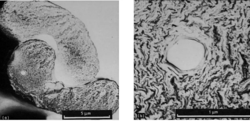
High-modulus pitch-based carbon fibers exhibit higher orientation than PAN-based carbon fibers. PAN-based carbon fibers have particulate morphology and smaller crystals (cf. Fig. 1.6), whereas pitch-based carbon fibers exhibit graphitic sheet-like morphology and larger crystals (cf. Fig. 1.7). The properties of carbon fibers strongly depend on the fiber microstructures and morphologies. The properties of some commercial carbon fibers are listed in Table 1.1.
Fig. 1.6 Scanning electron micrographs of PAN-based GY-70 carbon fibers at (a) low and (b) high magnification*.
Fig. 1.7 Scanning electron micrographs of pitch-based P-100 carbon fibers at (a) low and (b) high magnification*.
* Springer and Journal of Materials Science, 28, 1993, 423-439, Carbon fibre compressive strength and its dependence on structure and morphology, S. Kumar, D.P. Anderson, A.S. Crasto, Fig.12,15,17, with kind permission from Springer Science and Business Media.
Table 1.1 Properties of some commercial carbon fibers* Fiber Tensile Strength (GPa) Tensile Modulus (GPa) Diameter ( m) Elongation to Break (%) Density (g/cm3) Thermal Conductivity (W·m-1K-1) Electrical Resistivity ( ·cm) PAN-based Hextow AS4 4.47 231 7.1 1.8 1.79 6.83 1.7×10⁻³ Hextow IM10 6.96 303 4.4 2.1 1.79 6.14 1.3×10⁻³ Torayca T300 3.53 230 7 1.5 1.76 10.47 1.7×10⁻³ Torayca T700GC 4.9 240 7 1.8 1.8 - - Torayca M35J 4.7 343 5 1.4 1.75 39.06 1.1×10⁻³ Tenax HTS40 4.3 240 7 1.8 1.77 10 1.6×10⁻³ Pitch-based Nippon YSH-50A 3.83 520 7 0.7 2.1 120 7.0×10⁻⁴ Nippon YS-90A 3.53 880 7 0.3 2.18 500 3.0×10⁻⁴ Nippon XN-05 1.1 54 10 2.0 1.65 7.4 2.8×10⁻³ Thornel P-55 1.38 414 10 0.5 2.00 120 8.5×10⁻⁴ Thornel P-30 1.38 207 10 0.8 2.00 62 1.0×10⁻³
*Source: Reprinted from manufacturer’s technical literature.
Carbon fibers exhibit good thermal and electric conductivities along the fiber direction. The electrical and thermal conductivities increase with fiber tensile modulus and carbonization temperature. Pitch-based carbon fibers usually possess higher Young’s modulus and better thermal and electrical conductivity in the fiber direction, while PAN-based carbon fibers exhibit a higher tensile strength. Electrical resistivity of high-modulus carbon fibers is about 5-10 ·m, while that of high-strength carbon fibers is about 15-25 ·m [7]. For high-modulus pitch-based carbon fibers, the thermal conductivity can be greater than 500 W·m-1K-1 at room temperature. The transverse texture of mesophase carbon fibers is either radial or
flat-layer as shown in Fig. 1.8, which makes the fiber readily develop three-dimensional crystallinity. This structure gives pitch-based fibers superior lattice-dependent properties [9].
Fig. 1.8 Transverse textures of mesophase pitch-based carbon fibers. (Reprinted from Carbon, 36, D.D. Edie, The effect of processing on the structure and properties of carbon fibers, 2373, Copyright (1998), with permission from Elsevier)
1.2 Surface treatment and sizing of carbon fibers
To improve the adhesion between the carbon fibers and the matrix in a composite, different surface treatments and sizing of carbon fibers are often performed after the carbon fibers come out of the carbonization furnace. Generally, surface treatments of carbon fibers can be divided into oxidative and non-oxidative treatments.
1.2.1 Oxidative surface treatments
There are various methods of oxidative treatments, including dry oxidation in the presence of gases, plasma etching and wet oxidation [10].
Dry oxidative treatments are normally performed with air, oxygen and CO2 at
was improved by 45% when the temperature was raised to 600 oC, although a serious weight loss was accompanied. Scola et al. [12] treated the fibers for 60 s in N2
containing 0.1-1.8% O2 at 1000-1500 oC to improve their bonding characteristics in a
resin. There was no significant degradation of mechanical properties of the fibers. Dai et al. studied the effect of heat treatment on carbon fiber surface properties and fibers/epoxy interfacial adhesion [2]. T300B carbon fibers were heated in a vacuum drying chamber at 150 oC, 180 oC and 200 oC for several hours using controlled processing cycles. It demonstrated that the content of activated carbon atoms (conjunction with oxygen and nitrogen and hydroxyl) on the treated carbon fiber surface and the polar surface energy decreased with increasing the heat treatment temperature. Compared with the untreated fibers, the wettability studied by dynamic contact angle test between carbon fiber and E51 epoxy resin became worse. The results of micro-droplet tests demonstrated that the IFSS of T300B/epoxy reduced after the heat treatment process. This was attributed to the decrement of the amount of reactive functional groups in the interfacial region.
Plasma treatment has become a popular method for improving the fiber-matrix adhesion in recent years [13-23]. Plasma is a partially or fully ionized gas containing electrons, radicals, ions and neutral atoms or molecules. The principle of a plasma treatment is the formation of active species in a gas induced by a suitable energy transfer. Typical gases used to create a plasma include air, oxygen, ammonia, nitrogen and argon. Erden et al. [23] used continuous atmospheric plasma oxidation (APO) to introduce oxygen functionalities on the surface of carbon fibers in order to improve the interfacial adhesion between carbon fibers and polyamide-12 (PA-12). After the APO treatment, carbon fibers became more hydrophilic due to the introduction of polar oxygen-containing groups on the fiber surface, which also resulted in an increase of fiber surface energy. And the fiber tensile strength remained unaffected. The IFSS between carbon fibers and PA-12 increased from 40 to 83 MPa with up to 4 min of APO treatment. This can be attributed to the increase of surface oxygen content from 7 at.% to 16 at.%, which yielded more hydrogen bonds between fibers
and PA-12 matrix.
A number of liquid-phase oxidizing agents (e.g. nitric acid, acidic potassium permanganate, acidic potassium dichromate, hydrogen peroxide and ammonium bicarbonate) have also been used to treat carbon fiber surface. These liquid-phase treatments do not cause excessive pitting and hence degradation of the fiber strength [10].
Anodic oxidation is most widely used for treatment of commercial carbon fibers as it is fast, uniform and suited to mass production [24-27]. Carbon fibers act as an anode in a suitable electrolyte bath. A potential is applied to the fiber to liberate oxygen on the surface. Typical electrolytes include nitric acid, sulfuric acid, sodium chloride, potassium nitrate, sodium hydroxide, ammonium hydroxide and so on.
1.2.2 Non-oxidative surface treatments
Non-oxidative methods, including the deposition of an active form of carbon, plasma polymerization and grafting of polymers onto the fiber surface [28] have been used for the carbon fiber surface treatments.
Whiskerization involves the growth of thin and high strength single crystals, such as silicon carbide (SiC), silicon nitride (Si3N4) and titanium dioxide (TiO2) at
right angles to the fiber surface [29].
Many polymerizable organic vapors are used for plasma polymerization process, such as polyamide, polyimide, organosilanes, propylene, and styrene monomers. Plasma polymerization is demonstrated to increase the polar component of surface free energy of carbon fibers [30, 31].
1.2.3 Sizing of carbon fibers
from damage during subsequent textile processing, aid in handling, provide a chemical link between the fiber surface and the matrix and thus to improve the fiber-matrix adhesion [35].
Sizing can be achieved by deposition of polymers from solutions onto the fiber surface. The fibers pass through a sizing bath filled with organic solutions. The choice of sizing materials depends on the fiber type and the matrix resin. They must be compatible with the matrix resin, which allows the resin to penetrate into the fiber bundle and interact with the fiber surface. Typical sizing materials include epoxy, urethane, polyester and others. The sizing amount is 0.5-1.5 wt% of the fiber and the sizing layer is hundreds of nanometers thick [34].
Drzal et al. [36] have studied the effect of sizing on the adhesion of carbon fiber to epoxy matrix. They found that the sizing layer created a brittle interface layer between the fiber and matrix which improved the IFSS.
Dai et al. [37] have investigated the influence of sizing on the carbon fiber/matrix interfacial adhesion by comparing sized and desized T300B and T700SC carbon fibers. They found that the desized carbon fibers presented less concentration of activated carbon atoms (conjunction with oxygen and nitrogen) and lower polar surface energy, but higher dispersive surface energy and IFSS. The sizing agent on T300B and T700SC fiber surface was negative for the interfacial bonding. This is contrary to the general principles. Desizing reduced the acid parameter of carbon fibers surface which promoted bonding strength at the fiber/epoxy interface. The IFSS of T300B/epoxy increased from 63.72 MPa to 87.77 MPa after desizing, with an improvement of 38%. This was attributed to the increment of work of adhesion. The IFSS of desized T700SC/epoxy (89.39 MPa) was 9% greater than that of T700SC/epoxy (81.74 MPa). The thicker sizing might result in weak layer in the interface region. They concluded that IFSS for carbon fiber/epoxy systems depended not only on the chemical bonding but also on the physical and adhesive interactions.
1.3 Carbon fiber-matrix interface
In fiber-reinforced composites, both the fiber and the matrix keep their original physical and chemical properties. Meanwhile, a combination of mechanical properties is produced, which cannot be attained with either of the components acting alone [10]. That is due to the presence of an interface (or more properly named, interphase [38]) between these two constituents [10]. The issue of interface is of great interest in the design and manufacture of composite components.
1.3.1 General introduction to fiber/matrix interface
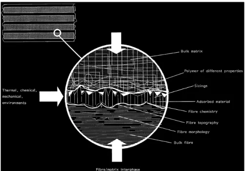
The interface in fiber-reinforced composites is a surface formed by a common boundary of fiber and matrix for the transfer of loads. The physical and mechanical properties of the interface are different from those of the individual bulk fiber and matrix. Since 1990, the concept of the fiber-matrix interface, which exists as a two-dimensional boundary, has been expanded into that of a fiber-matrix interphase that exists in three dimensions [39]. The interphase is a region different in structure and composition near the fiber-matrix interface. The interphase starts from some point in the fiber through the actual interface into the matrix. Fig. 1.9 schematically illustrates the concept of the three-dimensional interphase between fiber and matrix according to Drzal et al. [40].
Fig. 1.9 Characteristics of the fiber/matrix interphase in a composite material. (Reprinted from Composites, 23, P.J. Herrera-Franco, L.T. Drzal, Comparison of methods for the measurement of fibre/matrix adhesion in composites, 3, Copyright (1992), with permission from Elsevier)
Generally, interfacial adhesion can be attributed to major mechanisms including, adsorption and wetting, electrostatic attraction, chemical bonding, exchange reaction bonding, and mechanical bonding according to Kim [41].
Good wetting of the fiber by the matrix is important for proper consolidation of composites. Bonding due to wetting involves interactions of electrons on an atomic scale. Wetting can be quantitatively expressed in terms of the thermodynamic work of adhesion, WA, represents the thermodynamic work necessary to create a solid-vapor
surface and a liquid-vapor surface by pulling apart the solid-liquid interface.
WA= LV + SV – SL (1-1)
where LV, SV, SL are the surface free energies of the liquid, the solid, and the
solid-liquid interface, respectively. Good wetting occurs only when the surface energy of the fiber ( SV) is greater than that of the matrix ( LV). Contact angle measurements
resin matrix [42-45].
Chemical reactions occur between constituents at the interface region [46, 47]. A bond is created between the chemical group on the fiber surface and another compatible chemical group in the matrix. The bonds strength is decided by the number and type of bonds. The functional groups existing on the carbon fiber surface include -COOH, C-OH and C=O [48]. Surface oxidative treatments of carbon fibers are widely used to promote chemical bonding with polymer resins [26, 49].
Mechanical bonding is a significant mechanism of bonding in carbon fiber-polymer matrix composites. The interlocking at the fiber surface can be promoted by introducing large number of pits and corrugations to the carbon fiber surface or increasing the carbon surface area. The interfacial shears strength significantly depends on the degree of roughness [50, 51].
1.3.2 Effects of interface on composite performance
The final performance of composite materials depends not only on properties of fiber and matrices, but also on the quality of the fiber-matrix interface [52]. Good interfacial adhesion provides composites with structural integrity and efficient load transfer from fiber to matrix [53, 54]. The on-axis properties (such as longitudinal tensile, compressive, and flexural properties) are dominated by fiber properties, whereas the off-axis properties (such as transverse tensile and flexural, in-plane and interlaminar shear) and interlaminar fracture toughness are dominated by matrix and interfacial properties.
Drzal et al. [55] have established the correlation between the interface bond strength and mechanical properties of carbon fiber-epoxy matrix composites. A-4 PAN-based carbon fibers (Hercules, Inc.) with different surface conditions have been used. They have been designated as AU4, AS4 and AS4C which stand for “as received”, “surface treated” with an electrochemical oxidation procedure, and
obtained from a series of mechanical tests are summarized in Table 1.2 and Table 1.3.
Table 1.2 Summary of on-axis properties of carbon fiber- epoxy matrix composites with different fiber surface treatments [55]
Properties AU4/Epoxy AS4/Epoxy AS4C/Epoxy Interfacial shear strength (MPa) 37.2 68.3 81.4 Longitudinal tensile modulus (GPa) 130±9 138±5 150± 9 Longitudinal tensile strength (MPa) 1403±107 1890±143 2044±256 Longitudinal compressive modulus (GPa) 131± 8 126±9 153±8 Longitudinal compressive strength (MPa) 679 ±116 911±180 1174±207 Longitudinal flexural modulus (GPa) 154± 6 136±11 147± 5 Longitudinal flexural strength (MPa) 1662±92 1557 ±102 1827± 52
The interfacial shear strengths have been calculated from single fiber fragmentation tests, which also identify failure modes. After the surface treatments, there has been a significant increase in the IFSS. For AU4 fiber, the adhesion level was low, and frictional debonding was detected at failure. Pure interfacial failure occurred after surface treatment in the case of AS4 fiber. AS4C fiber has shown highest adhesion level due to better stress transfer between fiber and matrix and matrix cracking has been observed at fiber breaks. The failure mode has changed from interfacial to matrix.
The longitudinal tensile strength of has been found to increase with interfacial bond shear strength when the failure was interfacial. The compressive strength has been shown to be enhanced as fiber-matrix increase, which was attributed to the increase of the load necessary to cause the interface failure in transverse tension due to the Poisson effect under compression. In contrast, the longitudinal tensile and compressive moduli were insensitive to changes in fiber-matrix adhesion. There has
been little change in the flexural strength and moduli with low and intermediate interface. But for AS4C fiber which has shown strongest interface bond strength, there was a significant improvement in the flexural stiffness and strength due to the ability of the high modulus interface to suppress the interlaminar failure.
Table 1.3 Summary of off-axis properties of carbon fiber- epoxy matrix composites with different fiber surface treatments [55]
Properties AU4/Epoxy AS4/Epoxy AS4C/Epoxy Interfacial shear strength (MPa) 37.2 68.3 81.4 Transverse tensile modulus (GPa) 8.9±0.6 9.8±0.6 10.3±0.6 Transverse tensile strength (MPa) 18.0±3.9 34.2±6.2 41.2±4.7 Transverse flexural modulus (GPa) 10.2±1.5 9.9±0.5 10.7±0.6 Transverse flexural strength (MPa) 21.4±5.8 50.2±3.4 75.6±14.0 [±45]3s in-plane shear modulus (GPa) 9.1±1.5 6.2±0.5 6.0±0.2
[±45]3s in-plane shear strength (MPa) 37.2±1.8 72.2±12. 4 97.5±7.4
Iosipescu in-plane shear modulus (GPa) 7.2±0.5 6.4±1.0 7.9±0.4 Iosipescu in-plane shear strength (MPa) 55.0±3.0 95.6±5.1 93.8±3.3
Short beam interlaminar shear strength
(MPa) 47.5±5.4 84.0±7.0 93.2±3.8
From the values of the off-axis properties summarized in Table 1.3, it has been shown that all the strength values were sensitive to the interface adhesion, while the modulus values were relatively insensitive to the interface bonding. In particular, the transverse flexural strength can be a good indicator of the interfacial strength. In the case of ILSS, the Iosipescu method showed the least scatter among the three mechanical tests carried out. The failure in Iosipescu and short beam shear test specimens were matrix-dominated, while the ±45o specimen was relatively insensitive to the change in failure mode.
1.3.3 Characterization of interfacial properties of fiber composites
classified into two groups depending on the nature of specimens employed and the scale of testing: one includes the testing of microcomposites where individual fibers are embedded in matrix, such as the fiber pull-out test [67, 68], the indentation test [69, 70], the single-fiber fragmentation test [71, 72], and the embedded fiber compression test [73], as shown in Fig. 1.10 and Fig. 1.11; and the other uses bulk laminate composites to evaluate the interlaminar/intralaminar properties, some examples are given in Fig. 1.12 [56].
Fig. 1.10 Micromechanical tests in which external load is applied to the matrix: fragmentation test (a) and Broutman test (b)*.
pull-out (a), microbond (b), three-fiber test (c), and push-out (d)*.
*Reprinted from Composites Science and Technology, 65, Serge Zhandarov, Edith Mader, Characterization of fiber/matrix interface strength: applicability of different tests, approaches and parameter, 150-151, Copyright (2004), with permission from Elsevier.
Fig. 1.12 Schematic representation of laminate composite shear test. (Reprinted from Composites, 23, P.J. Herrera-Franco, L.T. Drzal, Comparison of methods for the measurement of fibre/matrix adhesion in composites, 22, Copyright (1992), with permission from Elsevier)
The fiber pull-out method has been developed in the early stages of composites research [74]. In this method, a fiber or a fiber bundle is partially embedded in a matrix block, a thin disc, or a droplet firstly. When the fiber is loaded under tension while the matrix block is gripped, the load and displacements are then monitored continuously during the whole debond and pull-out process. Fig. 1.13 shows a typical
by using the following equation [75]:
(1-2)
where df is the fiber diameter and lf is the embedded length. This technique can be
used for almost any fiber-matrix combination. But a relatively large scatter in the test data is obtained, which is attributed mainly to testing parameters such as droplet gripping, faulty measurement of fiber diameters, and so on.
Fig. 1.13. A typical force-displacement curve recorded during a pull-out test. (From the same source as Fig. 1.11 and Fig. 1.12)
Lu et al. [76] have prepared multi-scale CNT-hybridized carbon fibers by a newly developed aerosol-assisted CVD, and the BET surface area of the hybrid fibers was almost three times more than the original carbon fibers. Meanwhile, they have also investigated the interfacial shearing strength of a caron fiber-reinforced polymer composite with the produced CNT-hybridized carbon fiber and an epoxy matrix from the single fiber pull-out tests of micro-droplet composite, as shown in Fig. 1.14. A single fiber was pulled out from the cured epoxy droplet and the force to pull the fiber out of the epoxy was measured and used to calculate the IFSS.
Fig. 1.14 Schematic diagrams of single fiber pull-out test (a) and photograph of sample testing (b)[76].(Reproduced with permission from Elsevier)
The results indicated that the IFSS of the carbon fiber-reinforced polymer composite with the produced CNT-hybridized carbon fiber and an epoxy matrix was about 94% more than the original carbon fibers. The improvement of the IFSS was attributed to the fact that fiber surface area increased with the grafting of CNTs which resulted in the increase of the touching resin matrix region around the carbon fibers and finally provided a stronger interfacial properties.
The fiber fragmentation test is one of the most popular methods to evaluate the interface properties of fiber-matrix composites. It has been developed from the early work of Kelly and Tyson [77]. Here, a single fiber is embedded entirely in the middle of the matrix which is formed into a tensile dog-bone shaped specimen. The failure strain of the matrix material must be at least three times greater than that of the fiber. When the specimen is loaded in tension, the embedded fiber breaks into increasingly smaller fragments at locations where the fiber tensile strength is exceeded. The fragmentation process repeats until all fiber lengths are too short to allow its tensile stress to cause more fiber breakage. The IFSS can be estimated from the Kelly-Tyson model [77]:
where K adopts a mean value of 0.75, is the fiber diameter, is the fiber strength at the sauturation length . This technique yields a large amount of information for statistical sampling and replicates the events in-situ in the composite. But there are also some shortcomings in this method, such as the matrix must have a strain limit and sufficient toughness to avoid fiber fracture induced failure, the fiber strength should be known at the critical length and so on.
The microindentation technique is also popular for measuring the fiber interfacial shear strength [78]. The single fibers perpendicular to a cut and polished surface of an actual composite are compressively loaded using an indenter with various tip shapes and sizes. During the test, the force and indenter tip displacement are continuously monitored until the fiber detaches from the matrix. The IFSS may be obtained from:
(1-4)
where Fmax is the maximum applied force required for debonding and pushing a fiber
out of the specimen, df is the fiber diameter, lf is the fiber length (the thickness of the
specimen). The microindentation technique is an in-situ interface test for real composites and it reflects actual processing conditions. The drawbacks include crushing and splitting of fibers by the sharp indenter under compression, the inability to observe the failure mode or locus of failure.
Apart from the direct measurements of fiber-matrix interface properties as stated above, a number of methods have been designed to evaluate the fiber-matrix interface bond quality by inference from the gross mechanical properties such as ILSS, transverse tensile strength and translaminar shear strength [10, 40]. These techniques employ laminated composites reinforced with continuous and long fibers, whether unidirectional or cross-plied.
The short beam shear test is one of the most widely used laminate techniques. It is used to measures the ILSS. In this test, a beam fabricated from unidirectional laminate composites is loaded in three-point bending. The specimen has a
span-to-width ratio (L/h) chosen to produce interlaminar shear failure. The ILSS is given by:
(1-5) where Fmax is the maximum applied load, b is the specimen width and t is the
specimen thickness. An inherent problem in this technique is that the loading nose of small diameter induces stress concentration and non-linear plastic deformation.
1.3.4 Improvement of the interfacial adhesion between carbon fiber and matrix The carbon fiber/matrix adhesion is weak due to a chemically stable surface of carbon fiber. A large number of surface treatment techniques for carbon fibers have been developed to improve the carbon fiber-matrix interfacial adhesion through introducing more chemical reactive sites on the surface or increasing the fiber surface area.
Deng et al. [79] have grafted the diblock copolymer hydroxyl-terminated poly (n-butylacrylate)-b-poly (glycidyl methacrylate) (HO-PnBA-b-PGMA) onto the surface of the carbon fibers (cf. Fig. 1.15) and then studied the influence of the grafted polymers on the interfacial properties between carbon fibers and epoxy resin.
HNO3
COOH SOCl2 COCl
HO O Cl O O O O O O m n O O Cl O O O O O O m n C O Carbon f iber
Hydroxyl-terminated poly (n-butylacrylate)-b-poly (glycidyl methacrylate)
Fig. 1.15 Schematic illustration of grafting block copolymer onto carbon fibers [79]. (Reproduced with permission from Elsevier)
The results indicated that the IFSS of the carbon fiber/epoxy resin composites were significantly improved by the introduction of the diblock copolymer. The IFSS value increased with increasing length of the PnBA block in the copolymer when the polymerization degree of PnBA (DPn) was below 180, and then decreased with further increasing of the DPn of PnBA. But the length of PGMS block showed no obvious effect on the IFSS.
The application of a sizing to the carbon fiber surface is an efficient way to increase the fiber/matrix adhesion. Sizing makes the carbon fiber more compatible with the matrix, thus the wetting and impregnation of the fiber tow by the matrix is enhanced.
Marieta et al. [80] have investigated the influence of sizing on a high-strength carbon fiber in respect of interfacial adhesion in composite materials with a cyanate
matrix. Fig. 1.16 shows a comparison of the averages of the apparent IFSS values for the analyzed systems. The commercially sized carbon fiber possessed much higher apparent IFSS due to the chemical reactions that took place between the epoxy sizing and the bisphenol-A dicyanate resin during the curing process.
Fig. 1.16 Apparent IFSS data of the microcomposites based on the carbon fibers with different treatments and DCBA matrix by pull out measurements. (Reprinted from Composites Science and Technology, 62, C. Marieta, E. Schulz, I. Mondragon, Characterization of interfacial behaviour in carbon-fibre/cyanate composites, 307, Copyright (2002), with permission from Elsevier)
Zhang et al. [81] have studied the effect of emulsifier content in sizing agent on the carbon fiber surfaces and the interface of carbon fiber/epoxy composites. Carbon fibers were sized with different emulsifier content (10 wt%, 15 wt% and 20 wt%) sizing agent. The result showed that both the surface roughness and surface energy of the sized carbon fibers increased with increasing the emulsifier content in sizing agent. When higher content of emulsifier was used, the carbon fiber tensile strength and the IFSS became greater. They [82] have also studied the effect of emulsifier content of sizing agent on the carbon fiber surface by the atomic force microscopy (AFM) and it indicated that the emulsifier content had the important effect to improving the surface
using X-ray photoelectron spectroscopy (XPS) and it showed that the C-C was the major carbon functional components on the surface of carbon fibers samples and -C-OH, -C-OR and -C=N on the E-3 sized carbon fibers were more than that of other size agent sized carbon fibers. The effects of emulsifier content of sizing agent on the adhesion of surface on the interlaminar shear strength were also examined and it indicated that the 20 wt% of emulsifier content sizing agent (E-3) sized carbon fiber/epoxy resin composite showed better interfacial shear strengths.
Heat treatment is also a kind of surface treatments for carbon fibers to improve fiber/matrix adhesion by changing the fiber surface properties.
Bismarck et al. [83] have produced basic carbon fiber surfaces by heating fibers at 905 oC under nitrogen, cooling to 25 oC and then exposing them to oxygen. They have also produced basic carbon fiber surfaces by heating fibers in air at 385 oC. The contact angle of acidic carbon fibers versus water was lower compared with basic carbon fibers. Since thermoplastic materials contain acidic groups, the adhesion between the thermoplastic matrix and the carbon fiber could be improved due to acid-base interactions by a suitable thermo treatment.
Feih et al. [84] have studied the effect of fire on the tensile properties of carbon fibers and provided new insights into the tensile performance of carbon fiber-polymer composite materials during fire. By determining the reduction to the tensile properties and identifying the softening mechanism of T700 carbon fiber following exposure to simulated fires of different temperatures (up to 700 oC) and atmospheres (air and inert), they concluded that the fiber modulus decreased with increasing temperature (above ~500 oC) in air, which was attributed to oxidation of the higher stiffness layer in the near-surface fiber region. But the fiber modulus was not affected when heated in nitrogen due to the absence of surface oxidation, which indicated that the stiffness loss of carbon fiber composites in fire was sensitive to the oxygen content.
Dai et al. [85] have studied the reaction of the functional groups between the carbon fiber surface and the fiber surface sizing during heat treatment in detailed. The
results indicated that the concentration of epoxy groups in both the fiber surface sizing and the extracted sizing decreased with the increasing heat-treatment temperature, but it was lower in the extracted sizing compared with that of fiber surface sizing after heat treatment under the same conditions. It indicated that the reaction rate between the functional groups of fiber surface was higher than that of sizing system itself. Moreover, the content of C-O bonds and activated carbon atoms on the surface of the desized carbon fibers was highest after the heat treatment at 150
o
C, which proved the reaction between the functional groups on the surface of carbon fibers and the sizing materials.
Li et al. [86] have investigated the effect of heat treatments for T700 carbon fiber on properties of nitride matrix composites. T700 carbon fibers were oxidized at 400
o
C in air for 1.5 h or heated in an inert atmosphere at 1000 oC for 1 h. After the treatment, the oxidized fibers displayed rough surfaces, whereas the heat treated fibers exhibited relatively smooth surfaces like the as-received fibers. Both flexural strength and elastic modulus of oxidized fiber reinforced composite were visibly improved, and those of heat treated fiber reinforced composite were slightly changed. The interface between fiber and matrix can be effectively improved by the oxidation method.
In addition of the heat treatment, moisture also has effect on the interface between a carbon fiber and an epoxy matrix.
Liu et al. [87] have studied the interfacial toughness after water aging in T300 carbon fiber/5228 epoxy resin composite by the interfacial fracture energy, which was derived from the modified Wagner-Nairn-Detassis model. The results indicated that the interfacial fracture energy decreased obviously after immersion in boiling water and immersion in water at 70 oC and can recovery to the original level after re-drying treatments. The swelling of the resin matrix and interphase resulted in an increase in interphase thickness and a decrease in interphase bonding property, which indicated that the interphase thickness had a close relationship with the interfacial fracture
Zafar et al. [88] have prepared single fiber model composites based on an epoxy resin using high modulus carbon fibers and investigated the long term effects of moisture on the interface between a carbon fiber and an epoxy matrix. The results indicated that the glass transition temperature decreased after moisture absorption. The effects of moisture on the axial strain of the carbon fiber within the composite and stress transfer at the interface as a function of exposure time was observed using Raman spectroscopy, and it showed that the decrease in mechanical and interface properties of the model composites under the seawater immersion was more significant than under demineralised water immersion.
Another possible solution developed more recently for increasing IFSS is to graft CNTs directly onto the surface of the fibers via varied techniques [89-92]. As CNTs have a high aspect ratio and desirable thermal, electrical and mechanical properties, it is anticipated to create hybrid fibers with highly tailored surface area and properties.
Agnihotri et al. [93] have grown CNTs on the surface of carbon fiber/fabric using catalytic CVD at 550 oC. Different lengths and quantities of CNTs have been obtained by varying the CVD reaction time from 5 to 25 min. Both the density and length of CNTs on the fiber surface increased as the growth time increased and can attain a length greater than 50 m. After the heat treatment inside the CVD reactor, the elastic modulus and breaking strength of carbon fibers remained unchanged. The Tg of the CNT-coated fiber/polyester composites was same as that of the composite made from as received carbon fibers. The optimum CNT growth time was 15-20 min to improve the storage modulus of the multiscale composite and the pull out strength of single CNT-coated carbon fibers increased by as much as 33% and 88%, respectively. Both of the properties dropped significantly when the growth time was beyond 20 min.
Wang et al. [94] have used electrophoretic deposition method (cf. Fig. 1.17) to deposit vapor grown carbon nanofibers (VGCNFs) on carbon fibers and fabricated composites of the resulting hybrid material (CF-VGCNF) in an epoxy matrix by the vacuum-assisted resin transfer molding process. The results indicated that the electrical conductivities of the composites were significantly improved compared to
those without the VGCNF reinforcement.
Fig.1.17 Principle of electrophoretic deposition process [94]. (Reproduced with permission from Elsevier)
The Taguchi method was used to optimize the electrophoretic deposition process conditions (i.e. deposition time, applied voltage, concentration of VGCNF in a distilled water suspension, and the distance between anode (a carbon fabric) and cathode (a copper plate)) through the analysis of means and the analysis of variance for achieving a highly uniform deposition of carbon nanofibers. The results indicated that electrical conductivity of the CF-VGCNF/epoxy composite had a 51% improvement at the optimum deposition conditions that the deposition time is 5 min, the voltage is 40 V, the concentration of VGCNFs is 0.1 wt%, and the distance between electrodes is 10 mm.
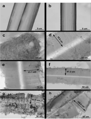
Lv et al. [95] have grafted multi-walled carbon nanotubes (MWCNTs) onto carbon fibers using an injection CVD method to increase the interfacial strength in carbon fiber/epoxy composites. Entangled and highly aligned MWCNTs (cf. Fig. 1.18) with different length were obtained by controlling the surface treatment of the carbon
nanotube growth, highly aligned MWCNT which were perpendicular to the fibers were gotten. That was because the strong adhesion between the catalyst and SiO2
coating leads to high density deposition. The length of nanotube array ranged from 16.6 to 108.6 m under the growth time at 30-120 min. The length of the MWCNT alignment increased with the growth time. The carbon fibers strength dropped after the growth of MWCNTs due to the surface damage caused by the catalyst iron etching and the thermal degradation at high temperature (850oC). A steady decrease was observed as the growth time increased. Particularly, for the fibers under 120 min of growth, the tensile strength decreased by around 33.5%. The carbon fibers grown with MWCNTs showed a good wettability according to the contact angle test. Compared to the pristine carbon fibers, there was an improvement of the IFSS between the hybrid fibers and the epoxy resin (Table 1.4). An optimum length (47.2 m) of aligned MWCNTs showed a remarkable improvement of the IFSS of up to 175%.
Fig. 1.18 SEM images of unsized carbon fibers (a) before and (b) after the surface treatment, and carbon fibers grafted by (c) entangled MWCNTs (sample 1) and (d–h) aligned MWCNTs (samples 2–6) with different length controlled by the growth time. (Reprinted from Carbon, 49,
P. Lv, Y. Feng, P. Zhang, H. Chen, N. Zhao, W. Feng, Increasing the interfacial strength in carbon fiber/epoxy composites by controlling the orientation and length of carbon nanotubes grown on the fibers,4668, Copyright (2011), with permission from Elsevier)
Table 1.4. Single fiber fragmentation test results
Sample CNTs Orientation CNTs Length ( m) IFSS (MPa) a - - 17.4 c Entangled N/A 22.3 d Aligned 16.6 25.2 e Aligned 23.1 32.3 f Aligned 47.2 47.8 g Aligned 63.5 46.1 h Aligned 108.6 42.9
A study of wetting and fiber fragmentation of CNT grafted carbon fibers was conducted by Qian et al. [42]. CNTs were grown on IM7 carbon fibers using a chemical vapor deposition method at 750oC for 1h. After the grafting process, the BET surface area increased by three times compared to the pristine carbon fibers. At the same time, the fiber tensile strength decreased by around 15% (depending on gauge length) which was resulted from the dissolution of iron particles into the carbon fiber surface during the high temperature growth reaction. The modulus was almost unchanged. Contact angles between carbon fibers and poly (methylmethacrylate) were directly measured using a drop-on-fiber systems and indicated that the CNT grafted carbon fibers possessed good wettability by the polymer. The results of single fiber fragmentation tests demonstrated a significant improvement (26%) of the apparent interfacial shear strength after CNT grafting, which correlated directly with a reduced contact angle between fiber and matrix. This was attributed to a more efficient stress transfer between the carbon fibers and surrounding matrix, through the grafted CNT
Storck et al [96] reported that shorter, higher density nanotube forests on the fiber surface yielded increases in interlaminar strength of the composite. Gains of up 36.2% in IM7 carbon fiber were seen. Conversely, nanotubes longer than two times the fiber diameter reduced interlaminar strength.
1.4 Carbon fiber-reinforced composites
In a carbon fiber-reinforced composite, at least one of the reinforcements is carbon fiber, short or continuous, unidirectional or multidirectional, woven or nonwoven and the matrix is usually a polymer, a metal, a carbon, a ceramic, or a combination of different materials [97-104]. Polymer-matrix composites are much easier to fabricate than composites made up with other matrix. Epoxy resins are the most common polymer matrix used with carbon fibers and currently constitute over 90% of the matrix resin material used in advanced composites [7, 105].
1.4.1 Manufacture process
There are numerous methods for fabricating fiber composites. The selection of a method will depend on the materials, the part design and the end-use.
Continuous fiber composites are commonly fabricated by hand lay and impregnation with a resin
high-pressure gases or a vacuum
shown in Fig. 1.19. The vacuum bagging process consolidates the plies a significantly reduces voids due to the off
stages.
Resin transfer molding (RTM) ports, under moderate pressure
which the reinforcement has already b used to produce continuous
limited to low-viscosity resins
in RTM are less expensive than prepreg material temperature.
Pultrusion is a relatively simple, low profile of constant cross-section
bath for impregnation, and gathered together to pro entering a heated die.
composites are commonly fabricated by hand lay
and impregnation with a resin. The fiber tapes or woven fabrics are placed in a die pressure gases or a vacuum is introduced via a bag to force the plies together as
The vacuum bagging process consolidates the plies a significantly reduces voids due to the off-gassing that occurs during the
ng (RTM) involves transferring the resin through
under moderate pressure (0.35-0.70 MPa) into a closed and clamped mold i which the reinforcement has already been placed (cf. Fig 1.20). This method
continuous carbon fiber composites of intricate shapes viscosity resins, such as epoxy. The dry reinforcements
RTM are less expensive than prepreg materials and they can be stored at room
Fig. 1.20 Resin transfer molding [106].
relatively simple, low-cost, continuous process section. The fibers is typically pulled through a
bath for impregnation, and gathered together to produce a particular shape before composites are commonly fabricated by hand lay-up of fibers are placed in a die and plies together as The vacuum bagging process consolidates the plies and
during the matrix curing
involves transferring the resin through injection 0.70 MPa) into a closed and clamped mold in This method can be hapes. But it is s and resins used can be stored at room
cost, continuous process, producing a through a heated resin duce a particular shape before
Filament winding is primarily used for hollow, generally circular or oval sectioned components. Fiber tows are wound continuous from a spool onto a mandrel in a variety of orientations. The fibers can be impregnated with a resin before or after winding. Three basic types of filament winding are hoop, helical and multi-directional winding.
1.4.2 Applications
Carbon fiber-reinforced composites have a wide range of applications because of their high performance and their ability to tailor fiber architecture to meet final performance requirements [107-111]. Nowadays, carbon fiber is indispensable in the aircraft/aerospace, sports, and recreation industries [112-116]. The main applications are shown in Fig. 1.21.
Fig. 1.21 Applications of carbon fiber-reinforced composites
Aircraft remains the dominant market for carbon fibers, where high specific properties have always been at a premium. Light weight, thermal stability and high
rigidity make carbon fiber a critical part in the modern aircraft/aerospace applications including primary and secondary structure for Boeing and Airbus civil aircraft, the International Space Station, satellites etc [117]. For the latest Boeing 777, carbon-fiber composites made up 7% of the total materials.
In the automotive industry, carbon fiber polymer-matrix composites are mainly used for saving weigh. Carbon fibers have been used in leaf springs and in transmission shafts on light trucks [7].
Another most significant application for carbon fiber composites is in sporting goods. These applications started early, and they were the largest market before significant aerospace applications existed. Typical products include golf club shafts, tennis racquets, fishing rods, bicycle components and skiing equipment.
The electrically conductive characteristic of carbon fiber polymer-matrix composites makes them suitable for elimination of static, electrodes, batteries and fuel cells [118-122]. In addition, carbon fiber polymer-matrix composites are used for the protection of aircraft from lightning strike [121]. The high thermal conductivity and low thermal expansion of carbon fiber composites make them attractive for heat dissipation components [123-127]. New applications of carbon fibers are developing at a rapid pace and the potential uses for carbon fiber are virtually limitless.
1.5 References
[1] Huang X. Fabrication and Properties of Carbon Fibers. Materials. 2009;2:2369-2403.
[2] Dai Z, Zhang B, Shi F, Li M, Zhang Z, Gu Y. Effect of heat treatment on carbon fiber surface properties and fibers/epoxy interfacial adhesion. Applied Surface Science. 2011;257:8457-8461.
[3] Jacobasch H-J, Grundke K, Uhlmann P, Simon F, MÄDER E. Comparison of surface-chemical methods for characterizing carbon fiber-epoxy resin composites. Composite Interfaces. 1995;3:293-320.
[4] Sherwood PMA. Surface analysis of carbon and carbon fibers for composites. Journal of Electron Spectroscopy and Related Phenomena. 1996;81:319-342.
[5] Weitzsacker CL, Xie M, Drzal LT. Using XPS to Investigate Fiber/Matrix Chemical Interactions in Carbon-fiber-reinforced Composites. Surface and Interface Analysis. 1997;25:53-63.
[6] Goodhew PJ, Clarke AJ, Bailey JE. A review of the fabrication and properties of carbon fibres. Materials Science and Engineering. 1975;17:3-30.
[7] Dorey G. Carbon fibres and their applications. Journal of Physics D: Applied Physics. 1987;20:245-256.
[8] Johnson DJ. Structure-property relationships in carbon fibres. Journal of Physics D: Applied Physics. 1987;20:286-291.
[9] Edie DD. The effect of processing on the structure and properties of carbon fibers. Carbon. 1998;36:345-362.
[10] Kim JK, Mai YW. Engineered Interfaces in Fiber Reinforced Composites. Oxford: Elsevier Science Ltd; 1998.
[11] Herrick JW, Gruber PE, Mansur FT. Surface treatments for fibrous carbon reinforcements. 1966. p. AFML-TR-66-178, Part I.
[12] Scola DA, Basche M. Treatment of carbon fibers. United States Patent 3720536; 1970.
[13] Morra M, Occhiello E, Garbassi F, Nicolais L. Surface studies on untreated and plasma-treated carbon fibers. Composites Science and Technology. 1991;42:361-372. [14] Commerçon P, Wightman JP. Surface characterization of plasma treated carbon fibers and adhesion to a thermoplastic polymer. The Journal of Adhesion. 1992;38:55-78.
[15] Yuan LY, Chen CS, Shyu SS, Lai JY. Plasma surface treatment on carbon fibers. Part 1: Morphology and surface analysis of plasma etched fibers. Composites Science and Technology. 1992;45:1-7.
[16] Yuan LY, Shyu SS, Lai JY. Plasma surface treatments of carbon fibers. Part 2: Interfacial adhesion with poly(phenylene sulfide). Composites Science and Technology. 1992;45:9-16.
[17] Allred RE, Schimpf WC. CO2 plasma modification of high-modulus carbon fibers and their adhesion to epoxy resins. Journal of Adhesion Science and Technology. 1994;8:383-394.
Carbon Fibers Used for Fiber/Epoxy Composites. Journal of Colloid and Interface Science. 1995;170:241-248.
[19] Vaidyanathan NP, Kabadi VN, Vaidyanathan R, Sadler RL. Surface Treatment of Carbon Fibers Using Low Temperature Plasma. The Journal of Adhesion. 1995;48:1-24.
[20] Chand N, Schulz E, Hinrichsen G. Adhesion improvement of carbon fibres by plasma treatment and evaluation by pull-out. Journal of Materials Science Letters. 1996;15:1374-1375.
[21] Bogoeva-Gaceva G, Mäder E, Haüssler L, Dekanski A. Characterization of the surface and interphase of plasma-treated HM carbon fibres. Composites Part A: Applied Science and Manufacturing. 1997;28:445-452.
[22] Pittman Jr CU, Jiang W, He G-R, Gardner SD. Oxygen plasma and isobutylene plasma treatments of carbon fibers: Determination of surface functionality and effects on composite properties. Carbon. 1998;36:25-37.
[23] Erden S, Kingsley KCH, Lamoriniere S, Lee AF, Yildiz H, Bismarck A. Continuous atmospheric plasma oxidation of carbon fibres: influence on the fibre surface and bulk properties and adhesion to polyamide 12. Plasma Chemistry and Plasma Processing. 2010;30:471-487.
[24] Yumitori S, Nakanishi Y. Effect of anodic oxidation of coal tar pitch-based carbon fibre on adhesion in epoxy matrix: Part 2. Comparative study of three alkaline solutions. Composites Part A: Applied Science and Manufacturing. 1996;27(11):1059-1066.
[25] Yumitori S, Nakanishi Y. Effect of anodic oxidation of coal tar pitch-based carbon fibre on adhesion in epoxy matrix: Part 1. Comparison between H2SO4 and NaOH solutions. Composites Part A: Applied Science and Manufacturing. 1996;27(11):1051-1058.
[26] Fukunaga A, Ueda S. Anodic surface oxidation for pitch-based carbon fibers and the interfacial bond strengths in epoxy matrices. Composites Science and Technology. 2000;60(2):249-254.
[27] Liu X, Yang C, Lu Y. Contrastive study of anodic oxidation on carbon fibers and graphite fibers. Applied Surface Science. 2012;258(10):4268-4275.
[28] Morgan P. Carbon Fibers and Their Composites: CRC Press; 2005.
[29] Goan JC, Prosen SP. Interfacial bonding in graphite fiber-resin composites. Interfaces in Composites, Philadelphia: ASTM; 1969. p. 3-26.
[30] Donnet JB, Guilpain G. Surface characterization of carbon fibres. Composites. 1991;22(1):59-62.
[31] Dagli G, Sung N-H. Properties of carbon/graphite fibers modified by plasma polymerization. Polymer Composites. 1989;10:109-116.
[32] Fitzer E, Weiss R. Effect of surface treatment and sizing of c-fibres on the mechanical properties of cfr thermosetting and thermoplastic polymers. Carbon. 1987;25(4):455-467.
[33] Yumitori S, Wang D, Jones FR. The role of sizing resins in carbon fibre-reinforced polyethersulfone (PES). Composites. 1994;25(7):698-705.
![Fig. 1.5 Schematic three-dimensional representation of structure in PAN-based carbon fibers [8]](https://thumb-eu.123doks.com/thumbv2/123doknet/14528708.723249/23.892.269.642.756.1038/fig-schematic-dimensional-representation-structure-based-carbon-fibers.webp)
![Table 1.2 Summary of on-axis properties of carbon fiber- epoxy matrix composites with different fiber surface treatments [55]](https://thumb-eu.123doks.com/thumbv2/123doknet/14528708.723249/33.892.131.769.247.607/table-summary-properties-carbon-composites-different-surface-treatments.webp)
![Table 1.3 Summary of off-axis properties of carbon fiber- epoxy matrix composites with different fiber surface treatments [55]](https://thumb-eu.123doks.com/thumbv2/123doknet/14528708.723249/34.892.148.769.354.707/table-summary-properties-carbon-composites-different-surface-treatments.webp)