HAL Id: hal-00646061
https://hal.inria.fr/hal-00646061
Submitted on 2 Dec 2011
HAL is a multi-disciplinary open access
archive for the deposit and dissemination of
sci-entific research documents, whether they are
pub-lished or not. The documents may come from
teaching and research institutions in France or
abroad, or from public or private research centers.
L’archive ouverte pluridisciplinaire HAL, est
destinée au dépôt et à la diffusion de documents
scientifiques de niveau recherche, publiés ou non,
émanant des établissements d’enseignement et de
recherche français ou étrangers, des laboratoires
publics ou privés.
Heterogeneous IPv6 Infrastructure for Smart Energy
Efficient Building
Leila Ben Saad, Cedric Chauvenet, Bernard Tourancheau
To cite this version:
Leila Ben Saad, Cedric Chauvenet, Bernard Tourancheau. Heterogeneous IPv6 Infrastructure for
Smart Energy Efficient Building. SDEWES, Sep 2011, Dubrovnik, Croatia. �hal-00646061�
Heterogeneous IPv6 Infrastructure for Smart Energy Efficient
Building
Leila Ben Saad
CITI INSA-Lyon, ENS Lyon, INRIA
Universit´
e de Lyon
Villeurbanne, France
e-mail: [email protected]
Cedric Chauvenet
Watteco Inc.
CITI INSA-Lyon - INRIA
La garde, France
e-mail: [email protected]
Bernard Tourancheau
CITI INSA-Lyon - INRIA
Universit´
e Lyon1
Villeurbanne, France
e-mail: [email protected]
Abstract
In the context of increasing developments of home, building and city automation, the Power Line Communication (PLC) networking medium is called for unpreceeding usage. Our view of the future building networking infrastructure places PLC as the central point. We show in this paper that even if Wireless Sensors Networks (WSN) are good candidates in several cases of the sensor and actuator networking infrastructure, PLC is mandatory in several place of the smart-grid metering and command infrastructure. Also PLC will serve the infrastructure on the sensor/actuator side when the energy requirement cannot be fulfilled by autonomous battery and capacitor based nodes. PLC may provide the numerous bridges necessary to sustain a long lifetime (years) for the WSN infrastructures. This new role of PLC networking will be possible only if the inter-operability between all media and technology is made possible. Thanks to the design of converging IPv6 networking layers, we show that full inter-operability is already possible even in very tiny constrained networking devices. Moreover, low energy PLC, will be able to provide smart grid monitoring without impacting the overall energy balance.
1
Introduction
Recent reports have shown that the energy consumption in building is responsible of 44% of the total energy consumption in 2007 in France [1]. This highlights a major need for energy savings. In existing and future buildings, the impact of occupants behaviors contributes significantly to the total energy efficiency. A recent study [2] has shown 31.9% reduction in energy consumption immediately after conducting an experiment which informs and encourages the occupants to reduce their energy consumption. However, after a month the reduction fell only to 3.7%, illustrating that relying on occupants to change their long-term behavior may be difficult. That is why Building Management Systems (BMS) that automatize the energy saving in the building are very important for a long lasting energy efficiency (EE).
In this paper, we focus on such a sensors/actuators network feasibility during the lifetime of smart buildings. Heterogeneity will be needed at the physical networking layer in order to provide several benefits. We propose an heterogenous networking architecture with wireless and PLC nodes associated to RF-PLC gateways. Such an architecture improves the overall smart-building network lifetime, its connectivity and its robustness.
The paper is organized as follows. In Section 2, related works are presented. Section 3 states the problem. Section 4 presents an hybrid RF-PLC architecture for smart building. In section 5, the performance of three networks using different technologies PLC, RF and RF-PLC are evaluated. In
section 6, a discussion of the benefits as well as the limitations of the proposed architecture is provided. Section 7 concludes the paper.
2
Problem statement
Recent years have witnessed an increasing need for RF-networks, often called wireless sensor networks (WSN), in a wide range of applications, specially for buildings automation. In fact, RF-networks are used as a way to reduce the waste of energy inside buildings by reporting essential information from the in-door environment allowing, for instance, to turn off the unnecessary electric appliances in the unoccupied rooms. Nevertheless, RF-network deployment inside buildings is a very challenging problem. Such networks are usually composed of low cost and battery powered devices, often called motes or nodes, with limited processing and memory capabilities. These nodes are interfaced with embedded sensor and actuator devices and are expected to operate for several years without any maintenance nor battery replacement. The nodes are deployed in smart buildings. They sense the environment and collaborate to forward the collected measurements towards the base station in the nodes’ meshed network. Thus, the nodes which are far away from the base station use multi-hops communication. This mean of communication makes the sensors near the base station deplete their energy much faster than distant nodes because they forward the packets of sensors located farther away in addition to their own packets. Therefore, what is known as a hole appears around the base station which makes distant nodes unreachable and unable to send their data. Consequently, the network lifetime ends prematurely while several nodes are still alive.
Special nodes without energy constraint called sinks were introduced to mitigate this problem by spreading the forwarding load among all the nodes. They collect the data and relay them to the base station. In addition, even if existing buildings monitoring will require some sort of autonomous system that will be battery powered with or without energy scavenging, some probes need a lot of energy to run and cannot be used with battery powered systems.
Wiring is costly and wireless networks are energy expensive, preventing long lasting fully meshed networks. However, power lines are already there, awaiting for powerline communication (PLC) without any additional wiring cost. Other technologies like Power-over-Ethernet (PoE) may offer power supply and communication on the same wire, but still needs an additional wiring network to the electrical grid. Reversing the idea of ”power over IP” used in PoE, we aim to use PLC to add ”IP over power”.
In a BMS and smart-grid approach, all communication media available have to be considered, in particular PLC. First because the bigger energy consumers are main powered and so have the ability of a PLC connection, and furthermore because most of the actuators and area controllers are also main powered as well as some sensors that need a lot of energy.
In this fashion and because sinks should be line powered and easy to deploy, we propose to equip them with a PLC interface, resulting in a RF-PLC gateway.
These gateways can be good candidates to play the role of sinks since they are small, inexpensive and consume less energy than the usual embedded PCs with wired and wireless communications.
They will be introduced in the network to provide the numerous bridges necessary to sustain a long lifetime for the RF-networks. These gateways will be connected together through their PLC interface, forming a PLC backbone.
The presence of the PLC backbone in the building will reduce hops between RF nodes with embedded sensors and their dedicated RF-PLC gateway, reducing thus packets forwarding and therefore energy consumption. The optimal solution to achieve the lowest consumption for RF devices is to deploy the RF-PLC gateways so that the routing distance between any RF node and its dedicated RF-PLC gateway is equal to one hop. By construction, most branches of the building’s electrical grid converge to the switchboard, which suggests that the distance between the RF-PLC gateway and the electrical switches that will gather these data may be equal to one hop in most cases, see [3, 4].
In this study, we aim to optimize the overall energy consumption of this hybrid network, extending its lifetime to the 10 year target. Considering the solutions employed to optimize this lifetime, we then discuss the constraints induced on the nodes’ performance for latency and throughput.
3
Related Work
BMS are not a new topic and have been installed in commercial buildings since the 1970s [5]. These systems typically control heating, ventilation, air-conditioning, lighting and elevator systems. Building access, security, smoke control and fire monitoring features are also deployed to increase the safety level of the building occupants. BMS were deployed as proprietary hardware and software solutions into the mid-1990s. The associated control networks were typically twisted pair copper wiring, and the protocols were proprietary. In the mid-90s, two open building automation and control network protocols (BACnet and LON) were developed within the industry that fostered interoperability of the software objects. In the first decade of the 2000s systems started to support native web services in the network controller layer of the architecture making the systems able to serve HTML and support other web technologies such as Obix and BACnet web-services. These developments have lead to a convergence of hardware platforms and an explosion of software interoperability. These days most BMS vendors use Ethernet IP running BACnet/IP or LON/IP for enterprise data and twisted-pair for control network communications in the lower layers of the architecture.
With the uprising of the ”Internet of Things” (IoT), buildings need new networking capabilities. The reflexion around the IoT and the introduction of IP based wireless sensor networks (WSN) lead up the IETF to define 6LoWPAN[6] and ROLL[7] formats and protocols that will clearly help IP network integration in BMS. Some requirements for building automation has been expressed in [8, 5] or promoted by the ”IP for Smart Objects” alliance (IPSO) [9] for such networking with a wireless solution reducing installation costs while maintaining highly reliant communication and an envisioned mix of wired and wireless sensors and actuators deployed within a building.
Moreover, considering the energy crisis, a BMS should pay for itself within a few years if it reduces the energy consumption by providing better EE and smart-grid valuable solutions.
Thus, we studied the possibility of IPv6 PLC networking for smart grid and sensor networking in such BMS [3]. Recently [10] showed some comparative work using PLC HomePlug standards as a backbone for smart buildings. It concludes that PLC is a viable technology for smart building’s wired devices, and endorses our proposal to run IPv6/6LoWPAN directly over the PLC links.
Using physical medium heterogeneity to improve sensor networks is not new. Several works e.g. [11] show that the introduction of sinks or relay nodes with unlimited energy resources to collect the data improves considerably the network lifetime. The majority of these studies assume that the communication between the sinks/relay nodes and the base station is assured by wifi radio communication or Ethernet. Moreover, the role of sinks is most of the time assured in testbeds by an embedded PC which makes the cost of the real deployment expensive.
Our work [3] has enabled interoperability between RF and PLC at the IPv6 level. This demonstrates the interest of such an interoperability, and highlight the gap with works that do not provide the IPv6 convergence that we focus on. [12] shows that a delivery success of 70% on PLC and 82% on RF rise up to 90% when both media are used together. In [13], The authors compare three communication methods to demonstrate that the combination of PLC and RF increases significantly the communication quality. Using RF and PLC together is an important issue and it needs a gateway that can be complicated if there is no easy interoperability between these media. Recent works around IPv6 for RF-network tackle this problem and enable efficient collaboration with a minimal overload.
This paper differs from previous works in the sense that the heterogeneity is insured by the use of RF-PLC gateways as sinks to collect the data from the sensors. These gateways have two network interfaces but a similar architecture than Low power and Lossy Network (LLN). This extends the boundary of such networks whereas previous works use border router that parses the network into several LLNs gathered by a high network capacity backbone. In a sense, we propose to modify the LLN from a network capacity backbone to an energy capacity backbone.
4
Hybrid RF-PLC architecture for smart buildings
The proposed heterogenous network for smart building benefits from the advantages of PLC networks and RF networks.
4.1
PLC background
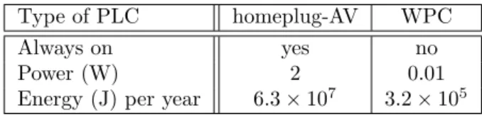
Table 1 shows that our PLC technology is very low power compared to existing standards.
Table 1: PLC technologies power consumption. Type of PLC homeplug-AV WPC
Always on yes no
Power (W) 2 0.01
Energy (J) per year 6.3 × 10⁷
3.2 × 10⁵
Many PLC communication protocols exist, almost as many as manufacturers. Some PLC devices aim to provide a high data rate (up to 200 Mb/s for Homeplug AV standard), with a power consumption, formfactor and cost that outcome the range needed for building automation.
Our experiments relies on a particular PLC transceiver called WPC. However, most of our results are not limited by this technology since our only assumption is a main powered low cost and low power network. WPC stands for Watt Pulse Communication. It is a technology developed by Watteco. It enables data transfer communication with a reliable propagation. This transceiver is based on the transient behavior of electrical networks. By using network reaction respect to load change, it is possible to create high level, low energy pulses compliant with EMC regulation. As a result, the pulse magnitude can be significantly higher than noise even after propagation and ensures a robust communication signal. The coupling device is very simple and the network reacts with its own resonance ensuring a very good propagation medium. This technology takes advantage of a physical natural phenomenon: the ignition pulse produced by appliances connected on an electric network. A pulse is a very short, a few nanoseconds, reactive signal produced by a load during its ignition or extinction and this constitutes an unambiguous signature. The WPC transceiver includes a microcontroller driving an adapted load, producing the pulse when connected to the mains. This pulse propagates over the power line at a long distance, up to 1 km in a public lighting environment. The emission of pulses can be triggered according to a controlled time schedule in order to communicate between two points in an electric network. As any PLC modem, a WPC module can re-use any existing protocol, providing a PLC adaptation of a communication stack. In this paper we consider the adaptation of the IEEE 802.15.4 standard protocol over PLC described in [3].
4.2
RF background
We focus here on radio technologies for LLNs. In this field, IEEE 802.15.4 standard stands as the dominant protocol for radio transceivers. This standard defines the physical layer and medium access control for Low-Late Wireless Personal Area Networks (LR-WPANs). It is vastly adopted by the industry and is the basis for the ZigBee or WirelessHART specification.
IEEE 802.15.4 radio transceivers focus on low-cost, low-speed communication between devices with little to no underlying infrastructure. Devices are often battery operated, so one of the biggest challenge in these networks is to limit their power consumption to reach an acceptable lifetime (up to 10 years). The basic framework offers a 10-meter communication range with a transfer rate of 250 kbit/s in the 2.4 GHz frequency band. Sub-GHz bands (868 MHz in Europe, 915 MHz in North America) can also be used with lower transfer rates of 20 and 40 kbit/s. 802.15.4-compliant radio transceivers consume a few tens of milliwatts, and can be set in sleeping mode to save energy. To that end, most of nodes using these transceivers have a duty cycling mechanism to wake up periodically the radio.
4.3
Architecture
Our heterogeneous architecture is composed of RF-only and PLC-only sensors or RF-PLC gateways. Since the all devices of the hybrid network are considered as LLN-type nodes, the architecture has to be low power, memory efficient, low data rate oriented and low energy consuming.
Relying on the 6LowPAN IPv6 design for such networks, figure 1 depict the network stack architecture of a RF-PLC gateway, designed in a route over fashion. RF-only and PLC-only sensors use the same
stack architecture restricted to one driver corresponding to the transceiver used.
Figure 1: Network stack proposition
As a result, all nodes from the hybrid network use the same protocols regardless of the media used. The routing protocol see nodes in a link-layer agnostic manner and construct a unique network. The bridge between RF and PLC is made at the network level (route-over).
4.4
Routing
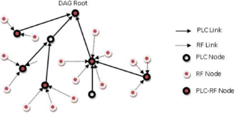
According to the architecture illustrated in figure 1 and the IETF 6LowPAN and RPL routing specifi-cation, topologies are directed acyclic graphs (DAGs). We suppose that every node run the same RPL implementation and maintains a path toward the root, according to the selected routing metric. The topologies shown in the figures 2 and 3 illustrate the PLC benefits in a RF-network topology. Depending on the Objective Function (OF) and the resulting metric(s), several topologies could be obtained. As defined in [14], the metrics can be Node Energy, Throughput, Latency or Link Reliability (either LQL or ETX).
Figure 2 shows a DAG formed by RF nodes only. We suppose here that the metric selected is a node energy estimation. To minimize their power consumption, RF nodes decrease their transmission power which reduces their radio range and creates a multi-hops topology. As shown in the figure 2, some nodes may be out of reach and form a floating DAG, resulting in network partitioning.
Figure 2: RF-Only DAG
Figure 3 shows a DAG formed by the three types of nodes considered : only, PLC-only and RF-PLC nodes. To maximize the non energy constraint nature of RF-PLC, we supposed that the metric selected in this case is the estimated energy of each node, selecting the less energy wasting path. Reliability metric like ETX may be used as a tie breaker.
As shown in the figure 3, the RF-nodes send their packets with sensors’ data to the nearest RF-PLC gateway which relays them to the PLC backbone. This latter one will be in charge to forward them using the PLC technology to the base station for further treatment.
According to [11] and [15], we can deduce that in order to achieve the optimal network lifetime of RF-networks, every battery powered node should be one hop away from a line powered node. In our case, every sensor should be able to reach a RF-PLC gateway in one hop. This can be obtained by the resolution of the problem of the optimal RF-PLC gateways placement.
Figure 3: Heterogeneous DAG
5
First experimental and simulated performance evaluations
In this section, the performance evaluation of three different types of networks is studied. The first network uses only PLC medium. The second one uses only RF medium. The latter one combines PLC and RF medium.
5.1
Testbed description
5.1.1 Hardware
The nodes are composed of the following hardware components: • controller (MSP430F5438, ATmega1281):
These microcontrollers are respectively 16 bit and 8 bit architecture designed for low power net-working applications. The MSP430 has 256 KB/16 KB and the ATmega has 128KB/8KB of ROM/RAM. Thus, the MSP offers more RAM to handle more routing entries and is more suitable for PLC/RF gateways or PLC nodes located along the path to the root, because they need to handle a possibly large subDAG. ATmega is fine for hosts like RF nodes.
• PLC transceiver:
In our testbed, we used WPC PLC transceivers from Watteco. This transceiver has a small size, a few cm2
, low power consumption, with less than 10 mW and a low price, less than a dollar per chip in large quantities. This transceiver offers actually 10 kbps baud rate. It is dedicated to home area networking, home automation or smart grid application.
• RF transceiver:
Our platform supports the following transceivers : CC2420, ATRF230, ATRF231 and ATRF212. In our Testbed, we used the first three, all offering a 250 kbps baud rate in the 2.4GHz band. The last one operates in the 868 MHz band.
5.1.2 Software • Contiki:
The network stack of all nodes relies on the Contiki OS [16]. Contiki is an open-source, highly portable, multi-tasking operating system for memory-efficient networked embedded systems. It is mainly oriented to sensor networks application and leverage on a growing community.
• Network Stack:
Our implementation relies on the network stack provided by the Contiki OS. It is based on its 6LoWPAN, IPv6 and RPL implementation. 6LoWPAN fragmentation and header compression is used. The RPL implementation is based on the 18th version of the draft and used in storing mode. It handles DIO, DIS, DAO, DAOACK, trickle timers management, local and global repair, and used the ETX metric.
5.2
PLC Network
We measured the performances of a real and a simulated PLC network implementing the network stack previously presented. The stack is implemented in the Contiki framework. We observed hops distribution, packet delivery ratio (PDR), throughput and latency.
Our real testbed is a 2 floors laboratory, composed of 25 rooms. We used 6 PLC nodes and a border router. PLC nodes were randomly plugged in outlets. The border router was never moved. After topology establishment, the border router sends 3 series of 30 pings to each node in his routing table with a delay of 2 seconds per hop between each ping in order to reduce collisions. Once the 3 series of 30 pings are done, we move all the PLC nodes into a new room, and repeat the scenario. The electrical network was submitted to real life activity.
The simulated network replays the scenarios obtained in the real testbed. The topology is recreated but links are set to be ideal (i.e. no loss) to quantify the loss of the real PLC media. PLC nodes were implemented in Cooja, the simulator integrated into the Contiki framework. This implementation includes PHY and MAC specificity of the PLC transceiver, voltage emulation and synchronization as well as a hardware emulation of the PLC nodes. The simulated nodes used the same software as real nodes.
5.2.1 Hops Repartition
As shown in the table 2, we always succeed to reach all the 6 PLC nodes through a 3-hops maximum path in all rooms tested from the border router location. This points out reliability, connectivity and forwarding reduction potential of PLC in a hybrid network. It is interesting to see that 85% of the nodes have been reached via a direct connection or through only one forwarder. This means that the topology of a backbone network made of PLC nodes should stay quite flat and limit the number of hops to reach the root.
Table 2: PLC testbed number of hops in each route to the server. Number of hops 1 hop 2 hops 3 hops
Route repartition 39% 46% 15%
5.2.2 Networking performances
(a) Throughput (b) Latency (c) Packet Delivery Ratio
Figure 4: Experimental and simulated results for PLC networking throughput, latency and PDR. As expected, the performances of the PLC network (PDR, Throughput and Latency) decrease with path length (number of hops).
Figure 4(a) shows that throughput is less impacted by real PLC links because it is only computed for successful transmissions. The throughput results correspond to the round trip time (RTT) that is necessary for the echo request/reply exchange. We set the ICMP payload to 10 Bytes, resulting in a packet of 46 bytes at the physical level, after 6LoWPAN header compression. This typically corresponds
to the size of an UDP frame in a metering or C&C network, carrying just a few bytes of payload. Throughput computed is impacted by the CSMA/CA mechanism which sets a random period of time before sending a packet. This time is included in the RTT computation.
Latency performances in figure 4(b) show that real PLC links induce many more link layer retries on real PLC networks. CSMA/CA uses an exponential backoff computation, resulting in possibly high latency value in the case of MAC layer retries. Furthermore, unlike RF media, the quantum of time used to compute these backoff is the voltage period of the electrical network (50Hz = 20ms in our case). These values are similar with RF systems using duty cycling mechanisms for energy efficiency and lifetime purpose.
PDR percentages in 4(c) reflect the looseness of the PLC media. As expected, PDR decreases with the number of hops. In the simulation, even with ideal links, 100% PDR is not reached because of collisions with traffic control messages. We observe that PLC can offer an average success ratio of more than 80% on a local link (1 hop Path) under real life activity and heavily loaded traffic.
5.3
RF Network
We simulated a WSN composed of 25 battery-operated RF-nodes and 1 RF-gateway which plays the role of the sink node. The nodes are distributed in a grid topology of 50x50m. The RF-gateway is located at the center. Each battery-operated node has an initial energy of 250 joules. The transmission range of each node is fixed to 10m. The nodes send a packet per minute of size 46 bytes to the sink . The packet are routed according to the shortest path with minimum number of hops. We used the typical model of energy consumption as specified in [17][18]. We analyzed the performance of the WSN in terms of network lifetime and energy consumption distribution.
5.3.1 Lifetime
There are many WSN lifetime definitions which depend on applications [19]. In this work, the widely used definition in WSN is adopted where the network lifetime is defined as the time until the first battery-operated node uses up all its residual energy. Let TRF denotes the network lifetime obtained with the RF-network using one RF-gateway.
5.3.2 Energy distribution
We analyzed the energy consumption of all battery-operated nodes at network lifetime. The energy consumption distribution at lifetime is depicted in the figure 5(b) where the lighter the color the higher the percentage of energy consumption on the node.
It is remarkable that the energy consumption of the nodes is highly variable and depends on the RF-gateway location. We notice that the nodes near the RF-gateway have relatively higher energy consumption compared to most of the others because they have to receive and relay all other neighbors data in addition to their own data. This leads them to consume more energy.
RF node RF gateway
(a) 1 DAG (b) Energy distribution with 1 RF-gateway
Figure 5: DAG construction and energy consumption distribution at lifetime end with 1 RF-gateway The results show that the percentages of the residual energy that remained unused at lifetime end is 63,57 %. Moreover, the number of battery-operated nodes which have more than 40 % of their initial
energy at lifetime is 21. This shows than the energy is not well balanced in case of RF-network with 1 RF-gateway.
5.4
RF-PLC Network
In this case, we consider a hybrid network composed of 25 battery-operated RF-nodes and RF-PLC gateways which play the role of sinks to collect the data and forward it to the base station. The RF-PLC gateways are optimally placed among the RF-nodes to maximize the lifetime following the work described in [20]. All others network assumptions are the same as the previous case.
5.4.1 Lifetime
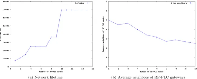
In the hybrid network, the network lifetime is significantly improved by the introduction of many RF-PLC gateways. In this example, the lifetime achieved is almost 10 × TRF.
The figure 6(a) shows that when the number of RF-PLC gateways grows the network lifetime increases until it reaches its maximum. In this case, the maximum is obtained with 10 RF-PLC gateways. This result corresponds to the case where all RF nodes are at one hop from RF-PLC gateways and no forwarding is done by any node. Moreover, with many RF-PLC gateways, the average length of routes decreases which leads to lower latencies.
The Figure 6(b) shows also that with higher number of RF-PLC gateways, the number of nodes directly connected to the RF-PLC gateway decreases. This leads to less congestion in the RF-PLC gateways and an improvement of the networking performance in terms of packet loss and latency.
(a) Network lifetime (b) Average neighbors of RF-PLC gateways
Figure 6: Network with 25 RF nodes and RF-PLC gateways
5.4.2 Energy distribution
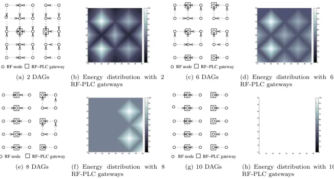
In Figure 7, we observe that when the lifetime ends, the higher percentage of energy consumption is concentrated around the locations of the RF-PLC gateways whereas the others RF nodes have a lower amount of energy consumption (dark color). With 10 RF-PLC gateways, the energy consumption of RF nodes is perfectly balanced. In fact, the majority of the nodes deplete their energy at the same time.
The results in Table 3 also show that the residual energy that remained unused at the network lifetime end decreases when the number of RF-PLC gateways increases. Moreover, the number of sensors which have more than 40 % of their initial energy decreases when the number of RF-PLC gateways increases. The best energy balancing of energy consumption is obtained when the network uses 10 RF-PLC gateways.
RF−PLC gateway RF node
(a) 2 DAGs (b) Energy distribution with 2 RF-PLC gateways
RF−PLC gateway RF node
(c) 6 DAGs (d) Energy distribution with 6 RF-PLC gateways
RF−PLC gateway RF node
(e) 8 DAGs (f) Energy distribution with 8 RF-PLC gateways
RF−PLC gateway RF node
(g) 10 DAGs (h) Energy distribution with 10 RF-PLC gateways
Figure 7: DAG construction and energy consumption distribution at lifetime end with many RF-PLC gateways
Number of RF-PLC nodes 2 6 8 10 % Unused Residual Energy 59.8 49.18 28.7 0 Nb sensors with more than 40% energy 18 15 15 0
Table 3: Comparison of Residual Energy at lifetime end
5.4.3 PLC backbone networking performances
We measured experimentally the maximum throughput achievable in a hybrid network. We vary the number of RF nodes connected to a RF-PLC node which forwards the data to a PLC node. Since RF medium offers higher throughput than PLC one, in our testbed we aim to see the maximum throughput the RF-PLC node can offer before the congestion occurs. The latency is correlated to the total throughput sent by the RF nodes to measure the congestion of the PLC link. The packet loss is also plotted to evaluate the reliability of the system.
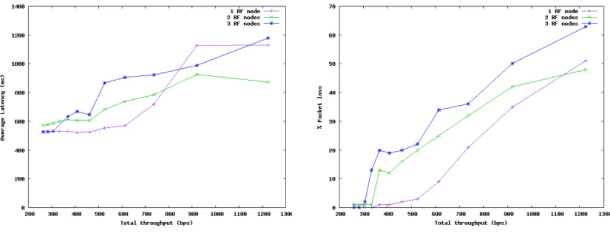
Figure 8(a) shows the average round trip time (RTT) of a 46 bytes packet sent from a RF node to a PLC node through a RF-PLC node. We plotted the RTT with respect to the average throughput received by the RF-PLC node to show the congestion of an hybrid RF-PLC network. Packets are sent sequentially by each RF nodes in a round robin fashion with a fixed interval. The throughput varies according to the time interval between each packet sent by RF nodes. As expected, more RF nodes connected to the RF-PLC node decreases the overall performances due to MAC issues. In our testbed, the MAC used was CSMA/CA so packet transmission is delayed if a node is already transmitting. The loss ratio in figure 8(b) shows that high throughput induces high loss. Because latency is only computed for successful transmissions, the average throughput is tweaked for higher throughput values. In our implementation, a packet is dropped after 3 MAC layer retries so that it bounds the maximum latency to about 2.5 seconds. In Figure 8(a), the interesting value is the point where the curve begin to rise up. This corresponds to the contention threshold. We can see that this point occurs for lower throughput if there are more RF nodes connected to the RF-PLC node. For instance, if only one RF node is connected to the RF-PLC node, we can reach an quite high average throughput (500 bps) with good reliability (3 % loss) and a close-to-minimum latency (550 ms). For 2 RF nodes, this threshold point slides to a lower average throughput (340 bps) with a similar latency (550 ms) and a low loss ratio (1%). Higher throughput significantly increases the loss ratio in this case. In the case of 3 RF nodes, the threshold is at 300 bps, with 1% loss and a similar latency of 550 ms. Like the latter case, higher throughput impacts
(a) Latency of the RF-PLC network (b) Packet loss of the RF-PLC network
Figure 8: PLC backbone network performances.
significantly the success ratio, but the overall performances drops quicker with 3 RF nodes. Connecting these templates with the lifetime study in section 5.4.1, we can say that with a network composed of 25 nodes placed in a grid, we could achieve an average throughput of 300 bps for each RF-PLC node, with very good reliability and a close to the minimum latency. Considering packets of 46 bytes at the PHY level, this corresponds to one packet sent each 1.2 seconds, which far exceeds the requirements of a metering application.
6
Discussion
Mixing PLC with wireless networks in the same topology for smart buildings offers many advantages. First of all we demonstrated that the network lifetime is significantly extended. This is explained by the fact that introducing many RF-PLC nodes reduces the forwarding of battery-operated RF nodes and thus balances the energy consumption of nodes.
Moreover, the works in [12] shows that the reliability is improved because the use of an alternative media like PLC in a network increases significantly path diversity and may cope better with link quality variations. PLC and RF are not sensitive to the same disturbers, so an hybrid network provides a more reliable path across these media.
In addition, PLC improves connectivity in low density wireless networks since it can reach zones that are unreachable via wireless links. Indeed, in a building context, one hop over PLC may join multiple floors whereas wireless links may be stopped by slabs.
The main drawbacks of such hybrid architecture may be the degradation of the network perfor-mances in term of latency and average throughput that we observed with heavy traffic on today’s WPC technology. Theses drawbacks will disappear with the use of improved PLC technology.
A balance between these advantages and drawbacks can be achieved with a fine metric computation. One metric could optimize energy consumption, whereas another one could optimize networking perfor-mances. Because these goals are orthogonal, a single metric could also provide an effective combination of them to reach a tradeoff, weighted by the needs of the application. Another possibility is to create two routing instances with distinct objective function. But, this needs that every node doubles its routing states, resulting in possibly memory issues.
In our simulated testbed where 25 RF nodes send packets of 46 bytes to the base station each 1.2 seconds, the lifetime achieved using 5 RF-PLC gateways is three times the lifetime obtained with one RF gateway. This result might be considered as a lower bound in a smart building. It is more likely to see improvements of 10 to 100 times in smart buildings when using one RF-PLC gateway per room containing many connected ”things”.
It is worth to note that the size, price and energy consumption of the hybrid node that we considered will be much more attractive than a high performances gateway with an ethernet or wifi interface to connect the stub networks.
7
Conclusion and future works
In this paper, we described a complete networking architecture for smart buildings which uses PLC nodes, RF nodes and RF-PLC nodes. The proposed hybrid architecture combines efficiently the two media RF and PLC to improve the lifetime and the reliability of the network. We presented the background of each technology and highlighted their complementarity. We determined the energy enhancement of such network and measured experimentally its performances. The results show that using 5 RF-PLC gateways in network composed of 25 RF nodes, we obtain 1% of packet loss and we can achieve up to threefold network lifetime improvement over the case of one RF gateway.
Future works concern scaling tests and real deployment of the proposed hybrid network inside a building. We intend also to study the appropriate metrics to use because they can have an important impact on the networking performances.
References
[1] (2007) La consommation ´energ´etique des bˆatiments et de la construction. [On-line]. Available: http://www.stats.environnement.developpement-durable.gouv.fr/donnees- essentielles/activites-humaines/construction-et-batiments/la-consommation-energetique-des-batiments-et-de-la-construction.html
[2] X. Jiang, M. Van Ly, J. Taneja, P. Dutta, and D. Culler, “Experiences with a high-fidelity wire-less building energy auditing network,” in Proceedings of the 7th ACM Conference on Embedded Networked Sensor Systems, ser. SenSys ’09. New York, NY, USA: ACM, 2009, pp. 113–126. [3] C. Chauvenet, B. Tourancheau, D. Genon-Catalot, P. Goudet, and M. Pouillot, “A
communica-tion stack over PLC for multi physical layer IPv6 Networking,” in Smart Grid Communicacommunica-tions (SmartGridComm), 2010 First IEEE International Conference on. IEEE, 2010, pp. 250–255. [4] C. Chauvenet and B. Tourancheau, “Heterogeneous plc-rf networking for llns,” HAL - INRIA, Tech.
Rep., 2011.
[5] S. Karnouskos, J. Vasseur, P. Wetterwald, J. Martocci, T. Humpal, and M. Zhu, “Introduction to ip in commercial buildings,” IPSO White Paper, 2010.
[6] G. Montenegro, N. Kushalnagar, J. Hui, and D. Culler, “Ipv6 over low power wireless personal area networks (6lowpan),” IETF RFC 4944, 2007.
[7] J. Vasseur, M. Kim, K. Pister, N. Dejean, and D. Barthel, “Rpl: Ipv6 routing protocol for low power and lossy networks,” IETF draft, 2011.
[8] J. Martocci, P. De Mil, N. Riou, and W. Vermeylen, “Building automation routing requirements in low-power and lossy networks,” IETF RFC 5867, 2010.
[9] Ip for smart objects alliance. [Online]. Available: http://ipso-alliance.org/
[10] P. Pannuto and P. Dutta, “Exploring powerline networking for the smart building,” in IP+SN workshop, 2011.
[11] M. Yarvis, A. Kushalnagar, H. Singh, Y. Liu, and S. Singh, “Exploiting heterogeneity in sensor networks,” in in Proc. of the IEEE Infocom, 2005.
[12] K. Yamada, Y. Hirata, Y. Naoe, T. Furumura, Y. Inoue, T. Shimizu, K. Yoshida, M. Kojima, and T. Mizuno, “Dual communication system using wired and wireless correspondence in a small space,” in Knowledge-Based Intelligent Information and Engineering Systems. Springer, 2004, pp. 898–904. [13] Y. Cai-fang and G. Ren-yi, “Home network using complementary communication system,” in In-ternational Seminar on Business and Information Management, 2008. ISBIM’08., vol. 1. IEEE, 2008, pp. 71–74.
[14] J. Vasseur, M. Kim, K. Pister, N. Dejean, and D. Barthel, “Routing metrics used for path calculation in low power and lossy networks,” IETF draft, 2010.
[15] S. Gandham, M. Dawande, R. Prakash, and S. Venkatesan, “Energy efficient schemes for wireless sensor networks with multiple mobile base stations,” in Global Telecommunications Conference, 2003. GLOBECOM ’03. IEEE, vol. 1, dec. 2003, pp. 377 – 381.
[16] The contiki operating system. [Online]. Available: http://www.sics.se/contiki/
[17] W. B. Heinzelman, A. P. Ch, IEEE, A. P. Chandrakasan, Member, H. Balakrishnan, , and H. Bal-akrishnan, “An application-specific protocol architecture for wireless microsensor networks,” IEEE Transactions on Wireless Communications, vol. 1, pp. 660–670, 2002.
[18] M. Bhardwaj and A. Chandrakasan, “Bounding the lifetime of sensor networks via optimal role assignments,” in INFOCOM 2002. Twenty-First Annual Joint Conference of the IEEE Computer and Communications Societies. Proceedings. IEEE, vol. 3, 2002, pp. 1587 – 1596.
[19] I. Dietrich and F. Dressler, “On the lifetime of wireless sensor networks,” ACM Transactions on Sensor Networks (TOSN), vol. 5, no. 1, pp. 1–39, February 2009.
[20] L. Ben Saad and B. Tourancheau, “Towards an optimal positioning of multiple mobile sinks in wsns for buildings,” International Journal On Advances in Intelligent Systems IARIA, vol. 2, no. 4, pp. 411–421, 2009.