RESEARCH OUTPUTS / RÉSULTATS DE RECHERCHE
Author(s) - Auteur(s) :
Publication date - Date de publication :
Permanent link - Permalien :
Rights / License - Licence de droit d’auteur :
Bibliothèque Universitaire Moretus Plantin
Institutional Repository - Research Portal
Dépôt Institutionnel - Portail de la Recherche
researchportal.unamur.be
University of Namur
Formal Modelling of Feature Configuration Workflows
Hubaux, Arnaud; Classen, Andreas; Heymans, Patrick
Published in:
Proceedings of the 13th International Software Product Lines Conference (SPLC'09), San Francisco, CA, USA
Publication date:
2009
Document Version
Early version, also known as pre-print
Link to publication
Citation for pulished version (HARVARD):
Hubaux, A, Classen, A & Heymans, P 2009, Formal Modelling of Feature Configuration Workflows. in D John & M Dirk (eds), Proceedings of the 13th International Software Product Lines Conference (SPLC'09), San
Francisco, CA, USA. SEI, Carnegie Mellon University, pp. 221-230.
General rights
Copyright and moral rights for the publications made accessible in the public portal are retained by the authors and/or other copyright owners and it is a condition of accessing publications that users recognise and abide by the legal requirements associated with these rights. • Users may download and print one copy of any publication from the public portal for the purpose of private study or research. • You may not further distribute the material or use it for any profit-making activity or commercial gain
• You may freely distribute the URL identifying the publication in the public portal ? Take down policy
If you believe that this document breaches copyright please contact us providing details, and we will remove access to the work immediately and investigate your claim.
Formal Modelling of Feature Configuration Workflows
Arnaud Hubaux, Andreas Classen
∗and Patrick Heymans
PReCISE Research Centre,
Faculty of Computer Science,
University of Namur
5000 Namur, Belgium
E-mail:
{ahu,acs,phe}@info.fundp.ac.be
Abstract
In software product line engineering, the configuration process can be a long and complex undertaking that in-volves many participants. When configuration is supported by feature diagrams, two challenges are to modularise the feature diagram into related chunks, and to schedule them as part of the configuration process. Existing work has only focused on the first of these challenges and, for the rest, assumes that feature diagram modules are configured se-quentially. This paper addresses the second challenge. It suggests using YAWL, a state-of-the-art workflow language, to represent the configuration workflow while feature dia-grams model the available configuration options.The prin-cipal contribution of the paper is a new combined formal-ism:feature configuration workflows. A formal semantics is provided so as to pave the way for unambiguous tool speci-fication and safer reasoning about of the configuration pro-cess. The work is motivated and illustrated through a con-figuration scenario taken from the space industry.
1
Introduction
In software product line engineering (SPLE), one distin-guishes two principal activities: domain engineering and application engineering[16]. Domain engineering consists in developing a set of core assets that can be configured and combined to create different products of the software prod-uct line (SPL). The variability provided by these assets is commonly documented in a feature diagram (FD) [13, 20]. During application engineering, this variability is progres-sively resolved in a configuration process. During this
pro-∗FNRS Research Fellow.
cess, it is decided which features created during domain engineering are selected for inclusion and which are dis-carded [4].
In a large industrial project, the configuration process it-self may be a complex activity taking up to several months and involving a variety of stakeholders [17]. This calls for ways (A) to elaborate large and complex FDs, (B) to distribute the configuration task among stakeholders and (C) to define and enact the workflow of the configuration process [19, 8, 11, 2].
Point (A) deals with the elaboration of the diagram, which is an important point, but not the focus of this pa-per. Point (B) was largely solved by the multi-level staged configuration (MLSC) approach of Czarnecki et al. [5] for which we provided a formal semantics in [2]. This ap-proach, however, fails to provide support for modelling and enacting the configuration process. The purpose of this pa-per is to provide a solution to this problem, and thereby address point (C). The recent issues faced by Spacebel, a partner company specialised in aerospace software, to mas-ter and betmas-ter decompose their configuration process were additional incitements to tackle this problem.
To do so, we build on our earlier work on formal se-mantics for FDs [20, 15, 2] and add the process perspective by linking FDs with YAWL [22], a state-of-the-art work-flow language. YAWL was originally introduced to sub-sume most workflow modelling languages [22], and comes with a formal semantics and powerful verification and ex-ecution tool. In essence, our approach consists in linking FDs to tasks and conditions of a workflow. This combined formalism, called feature configuration workflow (FCW), is given a complete mathematical semantics so as to avoid am-biguity and develop efficient and safe automated reasoning tools [12]. The formalisation follows the well-established guidelines of Harel and Rumpe [12], according to whom
each modelling languageL must possess an unambiguous mathematical definition for three distinct elements: (1) the syntactic domain LL, a.k.a. abstract syntax; (2) the se-mantic domain SL, which formalises the real-world con-cepts that the language models; (3)t he semantic function ML: LL → SL, also written[[·]]L, which defines the map-ping between both domains.
A preliminary evaluation of the language was carried out in collaboration with our industrial partner for an SPL of spacial file delivery protocol libraries (CFDP) [3, 7]. Al-though tool support is still to be provided, we propose an implementation strategy.
The paper is structured as follows. Section 2 introduces FDs, MLSC and YAWL, along with the CFDP product line which motivates the approach and serves as illustra-tion throughout the paper. We introduce the integrated se-mantics in Section 3 and illustrate it with the CFDP library. Section 4 addresses implementation strategies and Section 5 explores related work and discusses the benefits and limita-tions of the formalism. Section 6 concludes the paper.
2
Background
We briefly recall the concepts of FD and MLSC, show how they apply to the CFDP case, and what their limitations are. We also introduce YAWL, the workflow language we use in the remainder of the paper.
2.1 Feature diagrams and multi-level
staged configuration
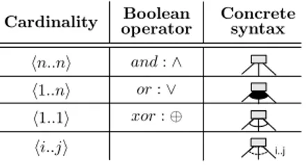
An FD [13, 20] models the variability of an SPL at a high level of granularity and, by that means, expresses the set of productsof the SPL; a product being a set of features. An example is shown in Figure 2. Basically, FDs are trees1 whose nodes denote features and whose edges represent top-down hierarchical decomposition of features. Features can be mandatory or optional. Optionality is often indicated with an empty circle on top of the feature. Each decompo-sition tells that, given the presence of the parent feature in a product, some combination of its children should be present in the product, too. Which combinations are allowed de-pends on the type of the decomposition, which is indicated by a cardinalityhi, ji: if a feature has k(≥ i) children, then if the parent is selected for inclusion in the product, at leasti and at mostj of its children have to be included in the prod-uct, too. For convenience, some common cardinalities are referred to by their equivalent Boolean operator, as shown in Table 1. FDs can also contain additional constraints that may crosscut the tree structure, usually specified in (a sub-set of) propositional logic [1]. Schobbens et al. surveyed
1Sometimes, directed acyclic graphs (a feature can have several
par-ents) are used, too.
Table 1. FD decomposition types
and : ∧ or : ∨ xor : ⊕ !n..n" !1..n" !1..1" !i..j" a a a a i..j
Cardinality operatorBoolean Concretesyntax
and formally defined FDs in [20]. Definition 1 recalls the essence of their formalism which we reuse in this paper.
Definition 1 (Feature Diagram [20]) Formally, an FD d can be defined as a tuple(N, r, λ, DE, Φ) where N is a set of features, r the root feature, λ assigns a decomposition operator to each feature, DE is the set of decomposition edges between features, andΦ the set of crosscutting con-straints. The semantics of an FD, noted[[d]]F D, is the set of
products (i.e. a set of sets of features) that it allows.
At the core of application engineering is the specification of the product to build [16]. In our context, this specifica-tion is obtained by configuring the FD, i.e. by gradually removing the variability until only those features that are part of the final product remain. In large industrial projects, the configuration has to be carried out in a modular way, each module focusing on a specific concern, task or role of the overall business. Identifying these modules is of ma-jor interest to practice since none of the stakeholders has the combined knowledge to configure the whole product, or because the product is developed by different teams [17, 5]. Czarnecki et al. proposed the concept of MLSC [5], where each FD denotes a module (Czarnecki et al. call it level) and modules are configured sequentially. Depend-ing on how the modules are linked, the configuration of one module induces an automatic specialisation of the next module’s FD. The links between modules are explicitly through inter-module links, that is Boolean formulae (sim-ilar to the constraints of Φ) over the features of the mod-ules [2]. Figure 1 gives an overview of an MLSC process in which configuration is carried out by different stakehold-ers having specific roles. These three roles configure their respective FDs in turn. Each FD only contains the features that correspond to the expertise and responsibility assigned to the role in the process. The inter-module links between the features are illustrated with dashed lines.
In earlier work, we provided a formal definition and semantics for MLSC as an extension of Definition 1 [2]. While the semantics of an FD is defined in terms of sets of products, the semantics of MLSC is defined in terms of configuration paths that can be taken when configuring a product. Along each such path, the initially full product
Global System Administrator Department System Administrator Local User Figure 1. Example of MLSC.
space ([[d]]F D) progressively shrinks (i.e., products are dis-carded) until only one product is left, at which point the path stops. The FDs corresponding to the various modules are organised in an FD collection as defined below. Whereas an FD specifies allowed products, an FD collection speci-fies allowed configuration paths. Hence, this is said to be a dynamicsemantics of FDs [2].
Definition 2 (Feature diagram collection [2]) Formally, an FD collection d = (N, L, r, λ, DE, Φ) is obtained by placing the FDs of individual modules under an and-decomposed artificial root, and adding the inter-module links to the set of constraints Φ. The set L defines a partition over the featuresN \ r accounting for the module decomposition. The semantics,[[d]]M LSC, is the set of legal
configuration paths.
Note that Definitions 1 and 2 deliberately omit the details of the semantics (available in [2]), since these are not crucial to the understanding of the paper. In the remainder, module names will be typeset with a frame: module .
2.2 Motivating scenario
Spacebel is a Belgian software company developing software for the aerospace industry. We collaborate with Spacebel on the development of a product line for flight-grade libraries implementing the CSSDS File Delivery Pro-tocol (CFDP) [7, 3]. The CFDP is a file transfer proPro-tocol specifically designed for space requirements, such as long transmission delays. The protocol was conceived to cover the needs of a broad range of space missions. For a given mission, however, only part of the protocol is used, and since resources for onboard software are limited, all CFDP implementations are actually mission-specific. Spacebel thus built an SPL of CFDP libraries, where each library can be tailored to the needs of a specific mission.
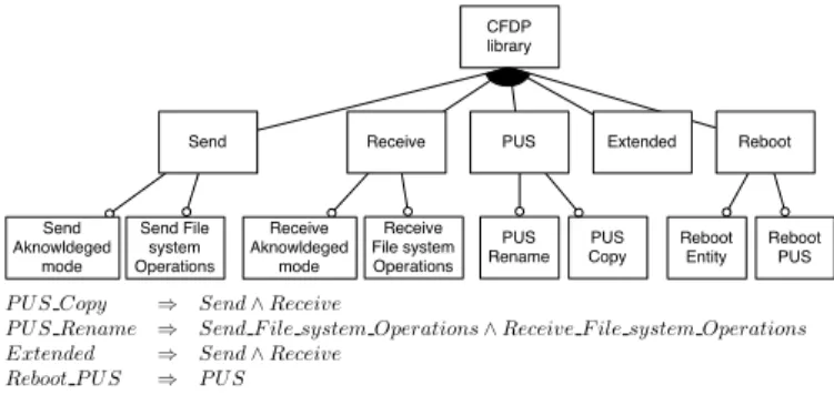
The FD of the CFDP library product line counts 80 fea-tures, has a maximal depth of four and contains ten addi-tional constraints. A simplified excerpt of this FD appears in Figure 2. The principal features provide the capability to send (Send) and receive (Receive) files. The Extended fea-ture allows a device to send and receive packets via other de-vices (such as a lander transmitting via an orbiting satellite).
CFDP library
Send Receive PUS Extended Reboot Reboot Entity Reboot PUS Send Aknowldeged mode Send File system Operations Receive Aknowldeged mode Receive File system Operations PUS Rename PUS Copy
P US Copy ⇒ Send ∧ Receive
P US Rename ⇒ Send F ile system Operations ∧ Receive F ile system Operations Extended ⇒ Send ∧ Receive
Reboot P US ⇒ P US
Figure 2. Sample FD of the CFDP library.
The Reboot feature allows the protocol to resume transfers safely after a sudden system reboot. PUS stands for Packet Utilisation Standard, part of the ESA standard for transport of telemetry and telecommand data (TMTC). TheP US fea-ture implements the CFDP related services of this standard.
The extensions to MLSC that we propose in this paper are motivated by the problems we encountered when apply-ing it to automate the CFDP configuration process. A num-ber of different stakeholders participate in the configura-tion of a mission-specific CFDP library. Initially, Spacebel decides which features are mature enough for the mission (flight-grade vs. ground station), while leaving as much variability as possible. In certain cases, a Reseller nego-tiates the contract. The Reseller can, depending on the contract, or for other commercial reasons, further config-ure the product. The configuration task is then passed on to the company that builds the software for the mission. The system engineer(SE ) makes initial high-level choices and passes the task of refining these choices onto the network integrator (NWI ) and the TMTC integrator (TTI ). These two configure in parallel the parts of the library they are responsible for. For technical reasons (e.g. reduction of available CPU time due to overruns by other components), integrators might have to come back to the SE to warrant or change some feature selections. The configuration can therefore be an iterative procedure until a final configura-tion is determined, and the library is finally delivered by Spacebel.
MLSC, as defined in [5, 2], is too restrictive to account for a complex scenario such as this one. Indeed, the original MLSC approach assumes the process to be purely sequen-tial, but this is not the case here: (1) the NWI and TTI per-form configuration in parallel, (2) the configuration by the reseller is optional, (3) the FD of Spacebel is not fully con-figuredwhen its intervention is over, and (4) configuration iteratesbetween SE and NWI/TTI.
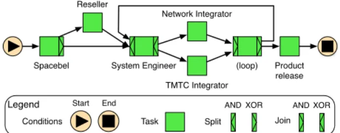
Spacebel Reseller System Engineer Network Integrator Product release TMTC Integrator Legend Conditions Start End Task Split AND Join XOR AND XOR (loop)
Figure 3. CFDP configuration workflow.
2.3 YAWL
As the limitations we just identified indicate, we need support for modelling and enforcing configuration pro-cesses that are more complex than mere sequences. Work-flow modelling languages and tools serve this purpose.
Among the possible options, we picked YAWL as it is formal [22], has extensive tool support [21] and is known to cover a large variety of real-world modelling patterns [23]. In [23], van der Aalst et al. conduct a study of 20 workflow patterns and compare the coverage of 15 workflow man-agement systems and associated languages. They conclude that the suitability of those systems “leaves much to be de-sired” [23], and propose YAWL as an alternative covering a maximal set of modelling patterns.
The scenario introduced in the previous section can be represented by the YAWL workflow shown in Figure 3. YAWL is inspired by Petri nets. Its principal constructs are conditions and tasks , which roughly correspond to places and transitions in Petri nets. There are two special conditions, start and end .2In Figure 3, each task, except for (loop) and Product release , denotes a configuration activity, and is annotated with the name of the stakeholder performing the configuration. Spacebel is split in two with aXOR split, meaning that only one of the outgoing transitions is executed, which captures well the optional na-ture of Reseller . System engineer joins both paths and then splits again, but this time with anAND split, meaning that the Network and TMTC integrator run in paral-lel. From there, the configuration process is either finished ( Product Release ) or continues with System engineer .
Formally, a workflow is defined as follows.
Definition 3 (Workflow [22]) A workfloww is defined as a tuple(C, i, o, F, T, split, join) where C denotes the set of conditions,i ∈ C is the unique start and o ∈ C the unique end condition (single entry and exit points of the workflow), F is the flow relation between conditions and tasks, T de-notes the set of tasks. split (resp. join) is the function de-termining the type of the task split (resp. join) behaviour, i.e.
2Generic conditions, illustrated in Figure 4, will be detailed later.
OR, AND, XOR. The semantics of w, noted [[w]]Y AW L,
is a transition system(S, →), and each state s ∈ S is a set of tokensx, where x is the condition in which the token resides.
The semantics of YAWL is based on a state space which only keeps track of active conditions, i.e. conditions that contain a token. Each task of a workflow is actually en-coded by four different conditions, and one of them indi-cates that the task is active. For a given taskt, we denote this conditionactiveCondition(t).
3
Feature configuration workflows
Having introduced FDs and YAWL, we now introduce the new combined formalism of feature configuration work-flows (FCWs) and illustrate it with the Spacebel case.
3.1 Formalism
In a nutshell, an FCW is a workflow, such as the one shown in Figure 3, where tasks are now associated with fea-ture modules: the FD will have to be configured during the task’s execution. We consider that the FDs configured in each task are different, and that the different FDs are related through inter-module links, i.e. they form an FD collection, just like in MLSC. For the Spacebel case, these FDs will be projections of the one shown in Figure 2.
Using YAWL to model the CFDP configuration process allows us to overcome the restrictions of MLSC identified in Section 2.2. From a purely structural viewpoint, it pro-vides an immediate solution to the representation of paral-lel modulesthrough AND split, optional modules through XOR split and iterative configurations through backward transitions.
Relaxing the limitation that FD modules be completely configured before passing on to the next module is of a more fundamental nature. Ideally, the formalism should be flexi-ble enough to overcome this limitation but rigid enough to enforce the time when modules have to be configured. This is achieved by specifying, separately for each module, the task in which it can be configured, and the point at which configuration has to be finished. This point is represented by a condition in the workflow.
We now provide a formal semantics for FCWs. As in [20, 2], the formalisation follows the best practice re-called in the introduction [12]. The following definitions formalises the intuitive description of FCWs we just gave.
Definition 4 (Abstract syntaxLF CW) An FCW m ∈ LF CWis a tuple(w, d, task, stop) such that:
• w is a workflow, i.e. w = (C, i, o, F, T, join, split). • d is an FD collection, i.e. d = (N, L, r, λ, DE, Φ).
• task ⊆ L × T is a total injective function assigning each module to a task in the workflow.
• stop ⊆ L×C is a total function assigning each module to a condition (itsstop) in the workflow.
Intuitively, the task of a module is the only task of the workflow during which the associated module can be con-figured, while the stop of a module denotes the point at which the configuration of a module needs to be done. The reason why task and stop of a module are dissociated, is to be able to capture cases where the partial configuration of a module is completed by subsequent modules, or where the configuration iterates, such as between the SE, the NWI and the TTI in the Spacebel case.
As forMLSC, the semantic domain of the F CW lan-guage is also based on the notion of configuration path, in-troduced informally in Section 2.1, and defined as follows.
Definition 5 (Semantic domainSCP [2]) Given a finite set of featuresN, a configuration path π is a finite sequence π = σ1...σn of length n > 0, where each σi ∈ PPN is called astage. If we call the set of such paths C, then SCP = PC.
This definition, however, only partially captures the intu-ition given in Section 2.1. Hence, addintu-itional constraints are given in Definition 6. Indeed, a configuration path should be a sequence that starts with all possible products (6.1) and where, at each step, at least one product is eliminated (6.2) until only one remains (6.3).
Definition 6 (Legal configuration path [2]) Given an FD d ∈ LF D, alegal configuration path π = σ1..σn is such that:
(6.1) σ1= [[d]]F D
(6.2) ∀i ∈ {2..n}•σi⊂ σi−1 (6.3) |σn| = 1
We are now set to define the semantics of an FCW. In this definition, we make use of the following helper that reduces a set of setsA to the sets containing elements of B. Definition 7 (ReductionA|B)
A|B 4
= {a ∩ B|a ∈ A}
The semantics of an FCW is the set of legal configura-tion paths (see 8.A in Definiconfigura-tion 8) which follow a valid sequence of workflow states (8.B). Intuitively, this means those configuration paths where the products eliminated in a step pertain to the module whose task is being executed (8.B.2), and where the stops encountered during the work-flow execution are respected (8.B.3). This intuition is for-malised by saying that each stage σ of the configuration
path can be associated to a step s in the workflow, i.e. a sequenceϕ of pairs (σ, s), that verifies the two above con-ditions and a minor well-formedness condition (8.B.1).
Definition 8 (FCW Semantics[[m]]F CW) For m ∈ LF CW,[[m]]F CW returns the set of pathsπ ∈ SCP such
that π = σ1. . . σn and a valid sequence of YAWL states ρ ∈ [[w]]Y AW Lsuch thatρ = s1→ . . . → sksuch that:
(8.A) let d0 be d without Lskip, π is a legal configuration path wrt.d0;
(8.B) ∃ a sequence ϕ : (σ1, s1), . . . , (σn, sk) such that: (8.B.1) both the configuration path and the workflow
se-quence evolve stepwise:
∀ . . . (σa, sb)(σc, sd) . . . ∈ ϕ
•(a = c ∨ a = c − 1) ∧ (b = d ∨ b = d − 1) (8.B.2) only one module is configured at a time, i.e. there
is no overlapping during module configuration:
∀ . . . (σa, sb)(σa+1, sb) . . . ∈ ϕ
•modules(sb) 6= ∅ ∧ ∃Li∈ modules(sb) •(σa\ σa+1)|Li6= ∅
∧ (σa\ σa+1)|Li ⊆ (σa|Li\ σa+1|Li)
(8.B.3) all the stops of the modules are satisfied:
∀(σa, sb) ∈ ϕ•∀Li∈ stops(sb)•|σa|Li| ≤ 1
where:
• c(s) is the set of conditions active in state s.
• modules returns the set of modules active in a given states:
modules(s) ⊆ L
•{Li|activeCondition(task(Li)) ∈ c(s)} • Lskip= L \ (Ss∈ρ modules(s)) is the set of modules
that do not appear in a given sequenceρ.
• Conversely, Ldo= L \ Lskipis the set of modules that do appear in a given sequenceρ.
• stops returns the set of modules that should be fully configured in a given states:
Configuration workflow Spacebel Reseller System Engineer Network Integrator TMTC Integrator
Final Satellite Product release
task(Spacebel) task(Reseller)
task(System Engineer) task(TMTC Integrator)
task(Network Integrator) stop(Network Integrator)
stop(TMTC Integrator) stop(System Engineer) stop(Spacebel) stop(Reseller) Legend Conditions
Start End Generic
Task Split
AND
Join
XOR AND XOR Worflow transition
Task assignment function Condition assignment function Spacebel FD CFDP library PUS Extended Reboot Send Receive Reboot Entity Reboot PUS Send Filestore Operations Send Aknowldeged mode Receive Filestore Operations Receive Aknowldeged mode PUS Copy PUS Rename Reseller FD CFDP library PUS Extended Reboot Send Receive Reboot Entity Reboot PUS Send Filestore Operations Send Aknowldeged mode Receive Filestore Operations Receive Aknowldeged mode PUS Copy PUS Rename Network Integrator FD CFDP library Send Receive
Send Filestore Operations Send Aknowldeged mode Receive Filestore Operations Receive Aknowldeged mode
TMTC Integrator FD CFDP library PUS PUS COPY PUS RENAME System Engineer FD CFDP library PUS Extended Reboot Send Receive Reboot Entity Reboot PUS (loop) 1 2 3 3
Figure 4. Example of FCW applied to the Spacebel scenario.
3.2 Motivating scenario revisited
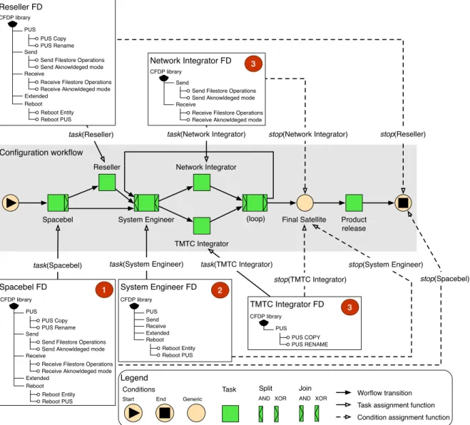
Section 2.2 introduced the configuration scenario of the CFDP. This scenario is now re-used to illustrate our defini-tion of FCW. Figure 4 depicts three types of artefacts: (1) the FD modules, (2) the configuration workflow and (3) the mappings between both. Note that the concrete syntax pre-sented here is used for illustrative purpose only and is not meant to be prescriptive.
The module decomposition is based on the sample dia-gram of Figure 2. The decomposition into modules of the original FD in Figure 2 produces five FDs, each account-ing for the roles and responsibilities defined in Section 2.2. (For readability, the FDs are shown in a directory tree-like fashion and the internal constraints are omitted.) Since the
individual FDs are all projections of a single diagram, the inter-module links are equivalence relations (⇔) defined pair-wise between all features. Indeed, for every feature in one module (e.g.,P USSin Spacebel ) for which there is a feature with the same name in another module (e.g.,P USR in Reseller ), there is an inter-module link requiring them to co-occur (i.e., P USS ⇔ P USR) in all products where one of them appears.
The configuration workflow is a simple extension of the one in Figure 3. The Final Satellite condition is added to indicate moment on which the SE, NWI and TTI have finished configuring the product.
The mapping of the modules to the tasks follows directly from the module decomposition. The map-ping to the stops, however, requires some further
ex-planation. The Final Satellite stop, to which three tasks System Engineer , Network Integrator and TMTC Integrator point, indicates the group formed by these modules: as long as the stop is not satisfied, the loop has to continue. The two other modules, including the op-tional Reseller module, map onto end , the second stop, since their configuration time does not matter. Note that, if the Reseller task is not executed, its features are not part of the configuration paths, meaning that the constraint 8.B.3 is automatically satisfied.
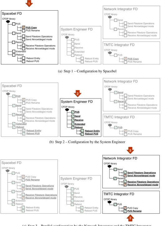
Figure 5 illustrates how this FCW can be executed, which eventually results in a fully configured product. The workflow starts with the Spacebel task (indicated by the arrow in Figure 5(a)), where the responsible per-son decides that the P US Copy feature shall not be in-cluded. As a consequence, the feature becomes unavail-able in the TMTC Integrator task. The next task is the System Engineer , who decides to include all the features that are available to him as shown in Figure 5(b). This decision again causes other features to be selected auto-matically, including those of the previous module. Finally, Network - and TMTC Integrator finalise the configura-tion process in parallel. Their choices eliminate all remain-ing variability, meanremain-ing that both stops are satisfied, and that the workflow has reached the end.
In the following section we look at how an automated tool could guide such a scenario.
4
Towards automation
In the life of an FCW, we distinguish roughly two phases: the elaboration phase and the usage phase. The tool support required during the elaboration phase needs to enable the construction of models that conform to the given abstract syntax (elements ofLF CW). Ideally, the tool should also allow to analyse them according to syntactic and semantic criteria. The usage phase, in the case of FCW, is the config-uration process. A tool supporting this phase should be able to enact the configuration process as specified by a given FCW.
The back-end for all but purely graphic tools is a rea-soner. In the present case, we make use of the reasoner inside the YAWL editor and execution engine [21], and of a logic truth maintenance system (LTMS) [10], derivative of a SAT solver, to reason about FDs.3 Similar to how YAWL and FD semantics were integrated in Definitions 4 and 8, these two back-ends have to be extended and integrated to produce FCW tool support. We first outline basic strategies
3An FD d can be easily encoded as a Boolean formula Γ
d ∈ B(N)
where the free variables are the features of d, so that, given a configuration c ∈ [[d]]F D, fi = true denotes fi ∈ c and f alse means fi 6∈ c [14,
1, 15]. The encoding of d into Γdis such that evaluating the truth of an
interpretation c in Γdis equivalent to checking whether c ∈ [[d]]F D.
for tool support and identify challenges; we then provide FCW analysis properties which are solutions to these chal-lenges.
Given the existence of editors for LF D and LY AW L, building a pure editor for LF CW is more of a technical than intellectual challenge; it suffices to add an interface allowing to assign modules to tasks and conditions. The real challenge is to extend such an editor with FCW-related features such as support for modelling patterns as well as analysis tasks that alert the user of possible problems with the FCW. While common analysis tasks for YAWL (e.g., check soundness) and FDs (e.g., check consistency) still ap-ply to the YAWL/FD parts of the FCW (allowing existing implementations to be reused), there are FCW-related anal-ysis tasks, detailed in the following section, that have to be added.
For the configuration tool, we can extend the implemen-tation strategy we already provided for MLSC [2]. Essen-tially, this consists in using an LTMS to maintain an ex-pression(Γd∧ ∆d) ∈ B(N) where Γdis the Boolean logic encoding of the FDd, and ∆drecords all decisions made by the user. Using an LTMS has several benefits: (i) it propa-gates implications of each new decision, (ii) it can be used to determine which features are included/excluded or yet to be decided, and, most importantly, (iii) since it always maintains a satisfiable expression, the LTMS will prevent the user from making decisions that would be incompatible with earlier decisions. To correctly implement the seman-tics of Definition 8, this strategy needs to be extended to take condition 8.B into account [21].
Here again, integration of the execution engine with a configuration tool is rather technical and can be done by message passing through web services. The real challenge is to prevent the user from making decisions that lead to dead ends: even though the LTMS can prevent inconsisten-cies of decisions and check satisfaction of stop conditions, it cannot readily predict (and prevent) unsatisfiable stop con-ditions, since they depend on the path taken in the work-flow. In such a case, the workflow execution would have to be rolled back to the task dealing with the configuration of the module in question, which, in real-world configuration processes, could mean a delay of several weeks.
We are currently working on solutions to these chal-lenges, which are required before efficient tool support can be implemented. Our preliminary findings indicate that ‘problematic’ workflows, i.e. those where unsatisfiable stop conditions might occur, can be identified by analysing the underlying workflow.
5
Discussion
After an overview of related work, we highlight the no-ticeable benefits of FCW and set forth the future work.
1 Spacebel FD CFDP library PUS Extended Reboot Send Receive Reboot Entity Reboot PUS Send Filestore Operations Send Aknowldeged mode Receive Filestore Operations Receive Aknowldeged mode
PUS Copy PUS Rename ✗ System Engineer FD CFDP library PUS Extended Reboot Send Receive Reboot Entity Reboot PUS Network Integrator FD CFDP library Send Receive
Send Filestore Operations Send Aknowldeged mode Receive Filestore Operations Receive Aknowldeged mode
TMTC Integrator FD CFDP library PUS PUS Copy PUS Rename ✗
(a) Step 1 – Configuration by Spacebel
2 Spacebel FD CFDP library PUS Extended Reboot Send Receive Reboot Entity Reboot PUS
Send Filestore Operations Send Aknowldeged mode Receive Filestore Operations Receive Aknowldeged mode PUS Copy PUS Rename ✓ ✓ ✓ ✓ ✓ ✗ ✓ ✓ System Engineer FD CFDP library PUS Extended Reboot Send Receive Reboot Entity Reboot PUS ✓ ✓ ✓ ✓ ✓ ✓ ✓ Network Integrator FD CFDP library Send Receive
Send Filestore Operations Send Aknowldeged mode Receive Filestore Operations Receive Aknowldeged mode
✓ ✓ TMTC Integrator FD CFDP library PUS PUS Copy PUS Rename ✓ ✗
(b) Step 2 – Configuration by the System Engineer
3 3 Spacebel FD CFDP library PUS Extended Reboot Send Receive Reboot Entity Reboot PUS
Send Filestore Operations Send Aknowldeged mode
Receive Filestore Operations Receive Aknowldeged mode
PUS Copy PUS Rename ✓ ✓ ✓ ✓ ✓ ✗ ✓ ✓ ✗ ✓ ✗ ✓ ✓ System Engineer FD CFDP library PUS Extended Reboot Send Receive Reboot Entity Reboot PUS ✓ ✓ ✓ ✓ ✓ ✓ ✓ Network Integrator FD CFDP library Send Receive
Send Filestore Operations Send Aknowldeged mode
Receive Filestore Operations Receive Aknowldeged mode
✓ ✓ ✓ ✗ ✓ ✗ TMTC Integrator FD CFDP library PUS PUS Copy PUS Rename ✓ ✗ ✓
(c) Step 3 – Parallel configuration by the Network Integrator and the TMTC Integrator
Figure 5. Example of valid module configuration derivable from Figure 4.
5.1 Related work
Dreiling et al. [9] claim that the knowledge about con-figuration processes is usually owned by experts, i.e. in-dividual employees or external contractors, on which the company is dependent. In order to gain independence in such situations, companies need to establish accurate inter-nal control structures. As a means to capture the configura-tion process explicitly, Dreiling et al.propose model-based
configuration. Thereby, they make the configuration pro-cess more intuitive to a larger audience, lower configuration costs and enhance process-awareness. Recker et al. [18] go along the same line and advocate a dedicated engineer-ing process integratengineer-ing configurable process models into the system development lifecycle. Although not specific for SPLE, the configurable process models they propose can be applied to any system in need of a flexible and sharp de-composition of tasks. In fact, FCWs, as we propose them,
also provide a means to capture configuration knowledge and to make it accessible to non-experts. In addition, FCWs capture information about the variability of the system.
Specific to SPLs, Deelstra et al. [6] report that prod-uct configuration is a “time-consuming and expensive ac-tivity”. That is, the gains of reusing core assets developed during domain engineering can be outweighed by the lack of adapted technologies to derive individual products dur-ing application engineerdur-ing. For that reason, they study the problems that can occur during product configuration and narrow the benefits from the upfront investments. Their re-sults notably show that both tacit knowledge and the lack of appropriate clustering of variation points are severe imped-iments to efficient product configuration.
Rabiser et al. [17] propose an approach supporting prod-uct configuration based on decision models (DMs). Essen-tially, decision models represent assets (e.g. features) tied to decisions, bound together through logic dependencies. De-cisions stand for the intervention of a role selecting assets during product configuration. Decisions, roles and assets are thus all part of a single DM. They also discuss how models need to be prepared to meet the requirements of a specific project before allowing product derivation.
5.2 Benefits
The primary benefit of FCWs is that they allow explicit modelling of non-trivial configuration processes, thereby overcoming the original limitations of MLSC and bringing assistance to the product management. From the resource allocation perspective, FCWs facilitate the task assignment to the different roles played by the stakeholders. From the control standpoint, stops of an FCW provide milestones for the project manager and keep him informed about the evo-lution of the configuration process, whereas feedback loops allow to define synchronisation points among roles.
The DMs proposed by Rabiser et al. [17] differ from FCWs in that the configuration process is entangled within the DM. By separating the workflow from the actual de-cisions (i.e. the feature modules), we argue that FCW achieves better separation of concerns between process and decision making. However, FCWs and DMs could be deemed complementary. Indeed, the FD that belongs to a module of an FCW could be readily replaced by a DM. This would preserve separation of concerns at the process level, while still offering fine-grained scheduling of the configu-ration process inside each module.
As pinpointed in Section 4, a direct consequence of the formal definition is the possibility to statically reason about FCWs. In order to make configuration less time-consuming and error-prone, FCW automation capitalises on existing analysis techniques for FDs and YAWL to provide a uni-fied reasoning framework supporting, for instance, illegal
FCW detection, FCW normal form evaluation and feature dependency resolution. Aside from FCW legality, one also wants to enforce that only valid products are built, which can only be guaranteed if every configuration stage respects the semantics of the FCW. The automated propagation of constraints, the prevention of illegal feature selection and the strict control over the executed tasks all contribute to safer and more efficient product configuration.
5.3 Future work
In its current state, our approach has some limitations that are subject to future work:
• As shown in Figure 4, configurations of Network and TMTC integrators are conducted in parallel. The strong assumption taken here is that both modules be-long to a shared FD enforcing configuration consis-tency along the process. However, it is very likely that real-life practices will demand support for asyn-chronous configuration, where decisions need to be merged at some point.
• Another practical aspect we abstracted from is the sim-ple fact that decisions might be changed or cancelled during the configuration process. Further investiga-tions should clarify whether the formalism should take such actions into account. It is, however, clear that a tool implementation needs to allow them.
• We assume that for an FCW there is a single partition of the variability space into modules, and that this par-tition is performed according to a single criterion (the role performing the action in the case of Spacebel). However, Gr¨unbacher et al. [11] assert that there ex-ist several ways to structure the variability space, and propose different views of a single model, such as the organisational structure and the market needs. We are currently working on adapting FCWs to similarly sup-port multiple views, or module decompositions, in or-der to better reflect current practices.
Beyond these limitations, numerous other extensions can be envisionned. For instance, so far we only made lim-ited use of the possibilities that YAWL offers since we ig-nored a number of constructs. Hierarchical workflows [22], for instance, could be used to specify the high-level work-flow of the whole SPL configuration process, whereas sub-workflows would correspond to single product configura-tion. Similarly, multiple task instances could be interpreted as feature cloning [4]. Furthermore, new case studies might reveal recurrent design patterns for the different elements of an FCW.
The validation of our approach is rather preliminary. In addition to the assessment from Spacebel, further studies
will be needed to confirm the suitability of FCWs to a large range of cases. Preferably, we will investigate industrial and open source cases including parallel and/or distributed product configuration.
6
Conclusion
In this paper, we introduced a new formalism called, Fea-ture Configuration Workflow (FCW), allowing to organise interrelated FDs as part of an unambiguous configuration workflow. For this formalism, we proposed a semantics that builds upon previous work on multi-level staged configura-tion and YAWL. We presented a tool implementaconfigura-tion strat-egy for automating relevant analyses. A preliminary evalu-ation with Spacebel, an industrial partner, helped to identify the benefits and needed extensions of the formalism. A thor-ough validation is still needed to ensure the applicability in a broader context.
Acknowledgements
We would like to thank Arnaud Bourdoux and Paul Pari-sis from Spacebel and Prof. Pierre-Yves Schobbens for their collaboration. This work is sponsored by the Interuniversity Attraction Poles Programme of the Belgian State of Belgian Science Policy under the MoVES project and the FNRS.
References
[1] D. S. Batory. Feature Models, Grammars, and Propositional Formulas. In SPLC’05, pages 7–20, 2005.
[2] A. Classen, A. Hubaux, and P. Heymans. A formal seman-tics for multi-level staged configuration. In VaMoS’09. Uni-versity of Duisburg-Essen, January 2009.
[3] Consultative Committee for Space Data Systems (CCSDS). CCSDS File Delivery Protocol (CFDP): Blue Book, Issue 4. Number CCSDS 727.0-B-4. National Aeronautics and Space Administration (NASA), January 2007.
[4] K. Czarnecki, S. Helsen, and U. W. Eisenecker. Formal-izing cardinality-based feature models and their specializa-tion. Software Process: Improvement and Practice, 10(1):7– 29, 2005.
[5] K. Czarnecki, S. Helsen, and U. W. Eisenecker. Staged con-figuration through specialization and multi-level configura-tion of feature models. Software Process: Improvement and Practice, 10(2):143–169, 2005.
[6] S. Deelstra, M. Sinnema, and J. Bosch. Product derivation in software product families: a case study. J. Syst. Softw., 74(2):173–194, 2005.
[7] L. Demonceau, P. Parisis, M. Ciccone, G. Furano, and R. Blommestijn. CCSDS file delivery protocol for future ESA missions. In DASIA’08. ESA Publications, May 2008. [8] D. Dhungana, T. Neumayer, P. Grunbacher, and R. Rabiser. Supporting evolution in model-based product line engineer-ing. In SPLC’08, pages 319–328. IEEE CS, 2008.
[9] A. Dreiling, M. Rosemann, W. van der Aalst, L. Heuser, and K. Schulz. Model-based software configuration: patterns and languages. European Journal of Information Systems, 15:583–600, 2006.
[10] K. Forbus and J. de Kleer. Building Problem Solvers. 1993. [11] P. Grunbacher, R. Rabiser, D. Dhungana, and M. Lehofer. Structruring the product line modeling space: Strategies and examples. In VaMoS’09. University of Duisburg-Essen, Jan-uary 2009.
[12] D. Harel and B. Rumpe. Modeling languages: Syntax, se-mantics and all that stuff - part I: The basic stuff. Technical Report MCS00-16, Faculty of Mathematics and Computer Science, The Weizmann Institute of Science, Israel, Septem-ber 2000.
[13] K. Kang, S. Cohen, J. Hess, W. Novak, and S.
Peter-son. Feature-Oriented Domain Analysis (FODA)
Feasi-bility Study. Technical Report CMU/SEI-90-TR-21, SEI, Carnegie Mellon University, November 1990.
[14] M. Mannion. Using First-Order Logic for Product Line
Model Validation. In SPLC’02, pages 176–187, Aug. 2002. [15] A. Metzger, P. Heymans, K. Pohl, P.-Y. Schobbens, and G. Saval. Disambiguating the documentation of variability in software product lines: A separation of concerns, formal-ization and automated analysis. In RE’07, pages 243–253, October 2007.
[16] K. Pohl, G. Bockle, and F. van der Linden. Software Product Line Engineering: Foundations, Principles and Techniques. Springer, July 2005.
[17] R. Rabiser, P. Grunbacher, and D. Dhungana. Supporting product derivation by adapting and augmenting variability models. In SPLC’07, pages 141–150. IEEE CS, 2007. [18] J. Recker, J. Mendling, W. Van Der Aalst, and M.
Rose-mann. Model-driven enterprise systems configuration. In Proceedings of the 18th International Conference on Ad-vanced Information Systems Engineering (CAiSE’06), 2006.
[19] M.-O. Reiser and M. Weber. Managing highly complex
product families with multi-level feature trees. In RE’06, pages 146–155. IEEE CS, 2006.
[20] P.-Y. Schobbens, P. Heymans, J.-C. Trigaux, and Y. Bon-temps. Feature Diagrams: A Survey and A Formal Seman-tics. In RE’06, pages 139–148, September 2006.
[21] W. van der Aalst, L. Aldred, M. Dumas, and A. Ter Hofst-ede. Design and Implementation of the YAWL System. In CAiSE 2004, 2004.
[22] W. van der Aalst and A. ter Hofstede. Yawl: yet another workflow language. Information Systems, 30(4):245–275, 2005.
[23] W. van der Aalst, A. ter Hofstede, B. Kiepuszewski, and A. Barros. Workflow patterns. Distributed and Parallel Databases, 14(3):5–51, July 2003.