HAL Id: tel-03173667
https://tel.archives-ouvertes.fr/tel-03173667
Submitted on 18 Mar 2021HAL is a multi-disciplinary open access archive for the deposit and dissemination of sci-entific research documents, whether they are pub-lished or not. The documents may come from teaching and research institutions in France or abroad, or from public or private research centers.
L’archive ouverte pluridisciplinaire HAL, est destinée au dépôt et à la diffusion de documents scientifiques de niveau recherche, publiés ou non, émanant des établissements d’enseignement et de recherche français ou étrangers, des laboratoires publics ou privés.
Knowledge-based decision support in CAM for additive
manufacturing : A rules mathematization approach.
Mouhamadou Mansour Mbow
To cite this version:
Mouhamadou Mansour Mbow. Knowledge-based decision support in CAM for additive manufactur-ing : A rules mathematization approach.. Computer Aided Engineermanufactur-ing. Université Grenoble Alpes [2020-..], 2020. English. �NNT : 2020GRALI082�. �tel-03173667�
THÈSE
Pour obtenir le grade de
DOCTEUR DE L
’
UNIVERSITÉ GRENOBLE ALPES
Spécialité : GI : Génie Industriel : conception et production
Arrêté ministériel : 25 mai 2016
Présentée par
Mouhamadou Mansour MBOW
Thèse dirigée par Frédéric VIGNAT , Maitre de Conférences, Université Grenoble Alpes
et codirigée par Philippe René MARIN , Grenoble INP et Nicolas PERRY , Resp Dept IMC de l'I 2 M / Resp Dept CIP Institut Carnot Arts, ENSAM
préparée au sein du Laboratoire des Sciences pour
la Conception, l'Optimisation et la Production de Grenoble
dans l'École Doctorale I - MEP2 - Ingénierie - Matériaux, Mécanique, Environnement, Energé tique, Procédés, Production
Aide à la décision basée sur l'expertise
métier
d
ans le domaine de la FAO pour la
fabrication
a
dditive : une approche par
mathématisation des
règles
.
Knowledg
e
-
based decision support in CAM
for
additive manufacturing:
r
ules
m
athematization
approach.
Thèse soutenue publiquement le 11 décembre 2020 , devant le jury composé de :
Monsieur ALAIN BERNARD
PROFESSEUR DES UNIVERSITES, ECOLE CENTRALE NANTES, Présidentde jury
Monsieur NABIL ANWER
PROFESSEUR DES UNIVERSITES, ECOLE NORMALE SUPERIEURE PARIS-SACLAY, Rapporteur
Monsieur LIONEL ROUCOULES
PROFESSEUR, ENSAM CENTRE AIX-EN-PROVENCE, Rapporteur
Monsieur FREDERIC VIGNAT
MAITRE DE CONFERENCES HDR, GRENOBLE INP, Directeur de thèse
Monsieur Nicol as PERRY
PROFESSEUR, ENSAM BORDEAUX, Co-directeur de thèse
Monsieur Philippe René MARIN
3 Dedicated to, Dédié à, May na ko, Khalifa Babacar, Soda, Alioune, Oumou, Aïda, Youssoufa et Fatim Fallou, Maoude Abdou Kane, Aïda Hann, Malick Tall ...
Acknowledgments
I would like to begin by thanking my supervisors Frédéric Vignat, Philippe Marin and Nicolas Perry for giving me the opportunity to do this thesis work in the laboratories G-SCOP in Grenoble and I2M in Bordeaux.This, through the COFFA project funded by the French National Research Agency (ANR) that I thank for the financial support of this thesis. Thanks to the time spent with the actors of this project, I learned a lot of things in rich and varied fields. I would like to express my gratitude to Philippe Marin and Franck Pourroy for having introduced me to the basics of research work during an internship prior to this PhD.
I am particularly grateful to Frédéric Vignat for his supervision and for the fact that he always pushed the work further, in order to have better results. I am grateful to the following people for their invaluable help in carrying out this work: Christelle Grandvallet, Guy Prudhomme, Marco Montemurro, Jérôme Pailhes, Gilles Foucault.
I would like to thank my parents Khalifa and Marème Soda, all my family in Senegal and my uncles Malick Tall and Abdou Kane for their support throughout my studies. I cannot thank enough my very dear Maoude who has been present during these three years to encourage and listen to me. Thank you for this attention. I am also grateful to my friends Mohamed Dieng, Nafissa Dia, Ibrahima Fall and Cheikhna Seck.
This work also went well thanks to the good mood of the colleagues at work and thanks to the music sessions of the Coffi-Coffa Band. I think especially of Akram, Manoch, Supasit, Cédric, Pierre Thomas, Vo Hoang, Amer, Rafael, Yohannes, Pascal, Clément, Matthieu, Nicolas, Maxime, Giulia and Soukaina. Finally, I would like to thank Alain Bernard, Lionel Roucoules and Nabil Anwer for having accepted to be members of my thesis jury.
Remerciements
J’aimerais commencer par remercier mes encadrants Frédéric Vignat, Philippe Marin et Nicolas Perry de m’avoir donné l’occasion d’effectuer ce travail de thèse au sein des laboratoires G-SCOP de Grenoble et I2M de Bordeaux. Ceci à travers le projet COFFA financé par l’Agence National de Recherche (ANR) que je re-mercie pour l’accompagnement financier de cette thèse. Grâce au temps passé avec les acteurs de ce projet, j’ai appris beaucoup de choses dans des domaines riches et variés. Je témoigne d’avantage ma reconnaissance à Philippe Marin et Franck Pourroy pour m’avoir initié aux bases d’un travail de recherche lors d’un stage précédent ce doctorat. Je remercie particulièrement Frédéric Vignat pour l’encadrement et pour le fait d’avoir toujours poussé plus loin les travaux, afin d’avoir de meilleurs résultats. Je suis reconnaissant aux personnes suivantes, pour leur aide inestimable dans la réalisation de ces travaux : Christelle Grandvallet, Guy Prudhomme, Marco Montemurro, Jérôme Pailhes, Gilles Foucault.
Je remercie mes parents Khalifa et Marème Soda, toute ma famille au Sénégal et mes oncles Malick Tall et Abdou Kane pour leur soutien tout au long de mon cursus d’études. Je ne saurai remercier assez ma très chère Maoude qui a été présente pendant ces trois années à m’encourager et à m’écouter. Merci pour cette attention. Je suis également reconnaissant à mes amis Mohamed Dieng, Nafissa Dia, Ibrahima Fall et Cheikhna Seck.
Ce travail s’est également bien déroulé grâce à la bonne humeur des collègues au travail et grâce aux session de musique du groupe Coffi-Coffa. Je pense spéciale-ment à Akram, Manoch, Supasit, Cédric, Pierre Thomas, Vo Hoang, Amer, Rafael, Yohannes, Pascal, Clément, Matthieu, Nicolas, Maxime, Giulia et Soukaina. Je fi-nis par adresser mes remerciements à Alain Bernard, Lionel Roucoules et Nabil Anwer d’avoir accepté d’être membres de mon jury de thèse.
8
Abstract
Pre-processing or CAM operations in additive manufacturing (AM) by powder bed fusion (PBF) include complex actions such as the definition of part orientation, the design of support structures, the nesting of parts, etc. The definition of the parts orientation in the manufacturing build space is the first step and several studies have shown that all of the remaining steps depend on it as well as the quality, cost and production time of the part. Its definition is given by only two rotation angle parameters in the global machine reference, but their definition is complex and requires strong skills in the field. Studies in the literature have shown that industrial users rely on their knowledge or expertise of the process to achieve this. Today, despite the technical advances, there is still a lack of tools or methods to take into account this formalized expertise. In this context, this thesis (from ANR COFFA project) proposes methods and tools to efficiently include the formalized knowledge of experts in the decision making process of CAM parameters, in PBF and AM in general.
As a first step, the review of methods to use expertise in decision making in traditional manufacturing CAM is presented in order to find the disadvantages and possibilities for integration in AM. Secondly, an investigation of the types of knowledge that can be used for decision support is carried out. This part of the work also explores the knowledge resources available for the definition of part orientation in the research literature but also in the industrial practice. The third part of the work presents a new approach for transforming knowledge of action rule type into desirability functions. This approach allows in particular to evaluate these action rules on parts and to obtain a quantitative appreciation which is considered as the level of respect of the rule (when the CAM parameters applied to the part). Then, this approach is applied to the action rules found in the second part of the work to establish quantitative models for the calculation of orientation desirability. Finally, a tool for the calculation of this orientation desirability and decision-making support is presented. The use of the tool is illustrated through case studies of industrial parts benchmarked with commercial tools, and through tests carried out with engineering school students.
The main output of this project is the provision of numerical means to assist CAM operators in their decision-making on optimal manufacturing parameters based on the company expertise. In addition, the approach presented offers the possibility of redesigning parts by targeting surfaces that have a low desirability with respect to the part orientation.
9
Résumé
Les opérations de préparation ou de FAO en fabrication additive (FA) par fusion sur lit de poudre (FLP) consistent en des opérations complexes telles que la définition de l’orientation des pièces, la conception des supports, l’imbrication ou le nesting des pièces, etc. La définition de l’orientation des pièces dans l’espace de production est la première étape et plusieurs études ont montré que toutes les étapes restantes dépendent d’elle tout comme la qualité, le coût ainsi que le temps de production des pièces. Sa définition n’est donnée que par deux paramètres d’angle de rotation dans la référence globale de la machine, mais leur définition est complexe et nécessite de fortes compétences dans le domaine. Des études dans la littérature ont montrées que les utilisateurs industriels se basent sur leurs connaissances métier pour y parvenir. Aujourd’hui, malgré les progrès techniques, il y a encore un manque d’outils et de méthodes pour prendre en compte cette expertise formalisée. Dans ce contexte, cette thèse (dans le cadre du projet ANR COFFA) propose des méthodes et des outils pour intégrer efficacement les connaissances formalisées des experts dans le processus de prise de décision sur les paramètres de la FAO dans le domaine de la fabrication additive.
Dans un premier temps, la revue des méthodes d’utilisation d’expertise dans la prise de décision en FAO de fabrication traditionnelle est présentée dans le but de trouver les inconvénients et possibilités pour une intégration en FA. En deuxième lieu, une investigation des types de connaissances pouvant être utilisés pour l’aide à la prise de décision est effectuée. Cette partie du travail explore également les ressources en connaissances disponibles pour la définition de l’orientation des pièces dans la littérature mais aussi dans la pratique industrielle. La troisième partie du travail présente une nouvelle approche pour transformer les connaissances de type règle d’action en des fonctions de désirabilité. Cette approche permet notamment d’évaluer ces règles d’action sur des pièces et d’obtenir une appréciation quantita-tive qui est considérée comme le niveau de respect de la règle (lorsque les para-mètres de la FAO s’appliquent à la pièce). Ensuite, cette approche est appliquée aux règles d’action trouvées dans la deuxième partie du travail pour établir des modèles quantitatifs destinés au calcul de la désirabilité d’orientation des pièces. Enfin, un outil de calcul de cette désirabilité d’orientation et d’aide à la décision est présenté. L’utilisation de l’outil est illustrée par des études de cas de pièces industrielles dont les résultats sont comparés à ceux d’outils commerciaux, et à travers des tests réalisés avec des étudiants en écoles d’ingénieurs.
ai-10 der les opérateurs de FAO à prendre des décisions sur les paramètres de fabrication optimaux en fonction de l’expertise de l’entreprise. De plus, l’approche présentée offre la possibilité de re-concevoir des pièces en ciblant les surfaces qui ont une faible désirabilité par rapport à l’orientation de la pièce.
Nota : Ce document est rédigé en anglais. Une version réduite en français est cependant disponible en fin de document.
A summarized french version is available at the end of this docu-ment.
Une version résumée en français est disponible à la fin de ce doc-ument.
Contents
Contents 12 List of Figures 16 List of Tables 20 Introduction 24Thesis Context and COFFA Project . . . 24
The Powder Bed Fusion Process Chain and Pre-processing Issues . 27 Research Question and Motivation . . . 31
Thesis Approach . . . 32
Manuscript Content . . . 33
1 Review of CAM Systems & Use of Knowledge for Assistance 34 Introduction . . . 34
1.1 Additive Manufacturing CAM Operations . . . 36
1.1.1 Part Orientation . . . 37
1.1.2 Definition of Regions to Support . . . 38
1.1.3 Design of the Support Structures . . . 39
1.1.4 Nesting . . . 40
1.2 Manufacturability Analysis . . . 40
1.2.1 In Traditional Manufacturing . . . 41
1.2.2 In Additive Manufacturing . . . 43
1.2.3 Additive Manufacturing Commercial CAM Tools . . . 45 12
CONTENTS 13
1.3 Knowledge Use in Manufacturing Pre-processing Operations . . . . 47
1.3.1 Limitations of the knowledge leveraging methods, for AM integration . . . 48
1.3.2 Proposal of a novel knowledge leveraging method for assist-ing AM pre-processassist-ing operations . . . 49
Conclusion . . . 50
2 Knowledge Typologies & Knowledge Resources in Additive Man-ufacturing CAM 51 Introduction . . . 51
2.1 Knowledge Typologies . . . 52
2.2 Available Knowledge in Additive Manufacturing . . . 54
2.2.1 Part orientation knowledge from literature . . . 55
2.2.2 Part orientation knowledge from industry practice . . . 61
2.2.2.1 AR1. Minimize part shadow on start plate. . . 61
2.2.2.2 AR2. Minimize total of overhanging non-machined surfaces . . . 62
2.2.2.3 AR3. Orient part priority surfaces (PPS) close to vertical . . . 63
2.2.2.4 AR4. Orient machining datum surfaces (MDS) out of horizontal . . . 64
2.2.2.5 AR5. Minimize shape deformation risks . . . 66
2.2.2.6 AR6. Avoid support structures and support re-moval difficulty on surfaces with potential support difficult to remove (SSDR) . . . 67
2.3 A Comparison between Research Literature and Industry Practice . 68 Conclusion . . . 70
3 A Knowledge Mathematical Representation Approach 72 Introduction . . . 72
About Desirability Functions . . . 73
Proposed Approach Overview . . . 74
3.1 Action Rule Codification . . . 76
3.1.1 Part: . . . 77
3.1.2 Evaluation Concept: . . . 77
3.1.3 Action: . . . 77
CONTENTS 14 3.3 Step 1 of Mathematization - Definition of the Evaluation Concept . 79
3.3.1 Identification of the variable . . . 80
3.3.2 Measurement of the variable on the shape entity . . . 81
3.3.3 Establishment of the relational function . . . 82
3.3.3.1 Example . . . 82
3.3.3.2 Fuzzification . . . 84
3.3.3.3 Operations on evaluation concepts . . . 84
3.4 Step 2 of Mathematization - Construction of the Desirability Function 86 3.5 Step 3 of Mathematization - Definition of the Summation Operator 89 3.5.1 Some discrete averaging operators . . . 89
3.5.2 Choice of the operator according to the action rule . . . 91
3.6 Summary and Conclusion . . . 93
4 A Knowledge-Based Computation of Part Orientation Desirability 96 Introduction . . . 96
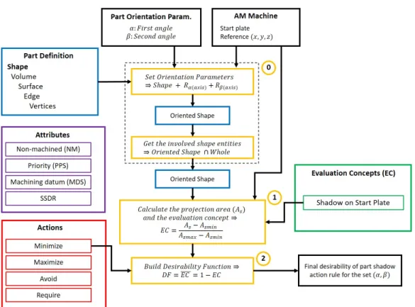
4.1 AR1 – Minimize part shadow on start plate . . . 97
4.1.1 Codification . . . 97
4.1.2 Mathematization . . . 97
4.1.3 Computation Algorithm . . . 99
4.2 AR2 – Minimize total overhanging non-machined surfaces . . . 99
4.2.1 Codification . . . 99
4.2.2 Mathematization . . . 100
4.2.3 Computation Algorithm . . . 103
4.3 AR3 – Orient Priority Surfaces Close to Vertical . . . 103
4.3.1 Codification . . . 103
4.3.2 Mathematization . . . 104
4.3.3 Computation Algorithms . . . 105
4.4 AR4 – Orient machining datum surfaces out of horizontal . . . 106
4.4.1 Codification . . . 106
4.4.2 Mathematization . . . 106
4.4.3 Computation Algorithms . . . 108
4.5 AR5 – Minimize Shape Deformation Risks . . . 108
4.5.1 Codification . . . 109
4.5.2 Mathematization . . . 109
4.5.3 Computation Algorithm . . . 113
4.6 AR6 – Avoid Support Structures & Support Removal Difficulty on Surfaces with Potential Support Difficult to Remove (SSDR) . . . . 118
CONTENTS 15
4.6.1 Codification . . . 118
4.6.2 Mathematization . . . 118
4.6.3 Computation Algorithm . . . 121
4.7 Summary & Conclusion . . . 122
5 COFFA: Knowledge-based Assistance of Part Orientation Defi-nition in AM 125 Introduction . . . 125
5.1 Tool for Computing Part Orientation Desirability . . . 125
5.1.1 Definition of Orientation Range to Explore . . . 127
5.1.2 Presentation of Results . . . 127
5.1.3 Design . . . 128
5.2 Tools for Decision Making Assistance . . . 129
5.2.1 Dashboard of Multiple Responses . . . 131
5.2.2 Aggregation into a Single Composite Response . . . 132
5.2.3 2D Superposition of Responses . . . 134
5.3 Case Studies of Industry Parts . . . 135
5.3.1 Case of a Topology Optimized Bracket . . . 137
5.3.1.1 Problem Definition . . . 137
5.3.1.2 Results & Discussion . . . 137
5.3.1.3 Benchmark with Commercial Tools . . . 140
5.3.2 Case of a Wavy Part: Re-Manufacturing with better Param-eters . . . 144
5.3.2.1 Problem Definition . . . 144
5.3.2.2 Results & Discussions . . . 144
5.3.2.3 Benchmark with Commercial Tools . . . 145
5.4 Testing COFFA with Students . . . 148
Conclusion . . . 150
Conclusions, Perspectives and Contributions 152 Conclusions . . . 152
Perspectives . . . 154
Contributions . . . 156
Bibliography 189
List of Figures
0.1 Collaborations between COFFA, KAMLAB and GeoCAM . . . 26
0.2 Powder bed fusion process . . . 28
0.3 Powder bed fusion value chain and process preparation operations . . . 29
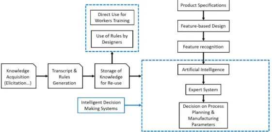
1.1 Classical scheme from design to manufacturing of components and man-ufacturing knowledge acquisition (adapted from Molcho et al. (2008)) . 35 1.2 Example of part orientation definition . . . 37
1.3 Support teeth and perforation . . . 39
1.4 Example of geometry decomposition – feature recognition . . . 43
1.5 Knowledge acquisition, analysis, storage and use in pre-processing (re-adapted from Kumar (2017)) . . . 47
1.6 Example of IF/THEN rules . . . 49
2.1 Sub-categories of knowledge (built based on results of Grandvallet et al. (2020)) . . . 54
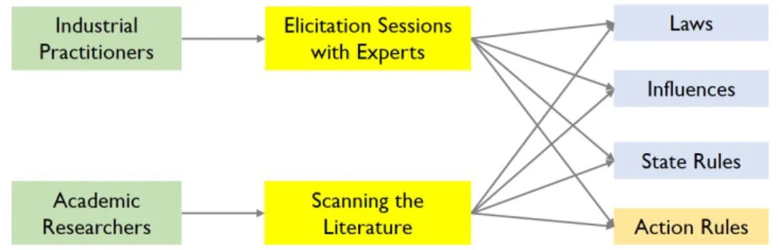
2.2 Knowledge extraction from academic researchers and industrial practi-tioners . . . 55
2.3 Illustration of staircase effect and support structures . . . 56
2.4 Overhanging surface definition . . . 62
2.5 Priority surface definition . . . 63
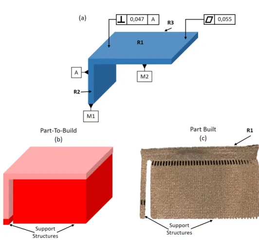
2.6 Example of part having machining datum surfaces: (a) product man-ufacturing information; (b) part to build with support structures; (c) manufactured component . . . 65
2.7 Loss of edge (adapted from Vo et al. (2018)) . . . 66
2.8 Simulated influence function for Ti6Al4V (adapted from Ghaoui et al. (2020)) . . . 67
2.9 (a) Illustration of support removal with screwdrivers; (b) Scenarios of removal with cutting tools . . . 69
LIST OF FIGURES 17
2.10 Top view of two different nesting strategies . . . 70
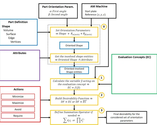
3.1 From literal to mathematical representation of action rule . . . 73
3.2 One sided and two sided desirability functions . . . 74
3.3 Modeling approach for knowledge quantitative representation . . . 75
3.4 Action rule concepts codification . . . 76
3.5 Categories of concepts: (a) Part classification; (b) Evaluation Concepts; (c) Actions . . . 78
3.6 Global methodology used to build desirability functions . . . 80
3.7 Choice of variable: part shadow example . . . 81
3.8 Action rule concepts codification . . . 83
3.9 Example of relational function . . . 84
3.10 Evaluation concept fuzzification: (a)quantified shadow; (b)fuzzified shadow 85 3.11 Desirability function built for the example . . . 87
3.12 Example of cubic part orientation scenarios . . . 88
3.13 2D L geometry with desirability function illustrating global desirability equivalence . . . 90
3.14 Relational diagram applied to part orientation . . . 95
4.1 AR1 codified and concept classification . . . 97
4.2 Desirability evaluation process for AR1 . . . 98
4.3 AR1 - Quantitative representation model: (a) Relational function; (b) Desirability function . . . 99
4.4 Illustration of part shadow on start plate . . . 100
4.5 AR2 codified and concept classification . . . 100
4.6 AR2 - Quantitative representation model: (a) Relational function; (b) Desirability function . . . 101
4.7 Desirability evaluation process for AR2 . . . 102
4.8 AR3 codified and concept classification . . . 103
4.9 AR3 - Quantitative Representation Model: (a) Relational function; (b) Desirability function . . . 104
4.10 Desirability evaluation process for AR3 . . . 105
4.11 AR4 codified and concept classification . . . 106
4.12 AR4 - Quantitative Representation Model: (a) Relational function; (b) Desirability function . . . 107
4.13 Desirability evaluation process for AR4 . . . 108
LIST OF FIGURES 18
4.15 Variable pertinence . . . 110
4.16 Layers intersections and maximum length . . . 111
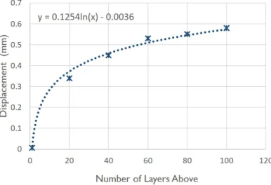
4.17 Shrinkage weighting function calculated from displacement function (chapter 2) for Ti6Al4V processed in EBM . . . 111
4.18 AR5 - Quantitative Representation Model: (a) Relational function; (b) Desirability function . . . 113
4.19 Example of part & plane intersection . . . 114
4.20 Two slicing sequences: (a) Scanning triangles with one plane; (b) Scan-ning planes simultaneously with one triangle . . . 115
4.21 Illustration of contour intersection . . . 115
4.22 Illustration of multi-directional hatching for contour maximum length measurement . . . 116
4.23 Continuous layer intersection full algorithm . . . 117
4.24 AR6 codified and concept classification . . . 118
4.25 Ray tracing for detecting surface accessibility . . . 120
4.26 AR6 - Relational functions: (a) Support structures requirement with respect of the angle; (b) Removal difficulty with respect of distance; (c) Negation of A – Desirability function; (d) Negation of B – Desirability function . . . 121
5.1 Response surface respresenting orientation scenarios . . . 128
5.2 General interface design . . . 129
5.3 Turbine with specifications . . . 131
5.4 Dashboard of multiple individual responses . . . 132
5.5 User interface for weighting responses . . . 133
5.6 Aggregated outputs with respect of weighting cases . . . 136
5.7 Result graphs: (a) 2D superposed charts; (b) Bar representation . . . . 137
5.8 Topology optimized bracket with different surface attributes . . . 138
5.9 Response surfaces for each action rule: (a) AR1; (b) AR2; (c) AR3; (d) AR4; (e) AR5; (f) AR6 . . . 139
5.10 Comparison of scenarios: (S1) α = 0◦− β = 60◦; (S2) α = 40◦ − β = 120◦; (S3) α = 90◦ − β = 180◦; (S4) α = 90◦− β = 50◦ . . . 141
5.11 (a)Approximate correspondance between results in Additive Prep and COFFA; (b) Heatmap provided by Additive Prep . . . 142 5.12 Part oriented using Additive Prep and COFFA for the scenarios compared143
LIST OF FIGURES 19 5.13 First manufacturing trial without assistance based on action rules: (a)
Oriented CAD part; (b) Manufactured with marks and non-removed
support block . . . 145
5.14 3D response surfaces: (a) SSDR desirability; (b) Overhanging surfaces desirability; (c) Bar graph comparing SSDR and overhanging action rules for a series of orientation scenarios. . . 146
5.15 Second manufacturing trial with assistance based on action rules: (a) Oriented CAD part; (b) Manufactured cleaned part; (c) Manufactured part before powder and support removal . . . 147
5.16 Approximate correspondance between results . . . 148
5.17 Tests with engineering students: (a) Generic clamp; (b) Topology op-timized clamp; (c) Manufactured considering optimal orientation; (d) Manufactured without considering optimal orientation. . . 149
5.18 Desirability-based re-design of oriented part . . . 156
5.19 De l’acquisition à l’utilisation de la connaissance en FAO (schéma adapté de Kumar (2017)) . . . 164
5.20 Décomposition de géométrie – Feature Recognition . . . 164
5.21 Approche de modélisation des règles d’action en fonctions mathématiques170 5.22 Codification des concepts d’une règle d’action . . . 171
5.23 Categories de concepts : (a) Géométrie; (b) Concepts d’Evaluation; (c) Actions . . . 172
5.24 Exemple de fonction relationnelle . . . 175
5.25 Fonction de désirabilité . . . 176
5.26 Exemple de scénarios d’orientation d’une pièce cubique . . . 176
5.27 AR1 codifiée - classification des concepts . . . 180
5.28 Choix de la variable . . . 180
5.29 AR1 - (a) Fonction relationnelle ; (b) Fonction de désirabilité . . . 181
5.30 AR6 codifiée - classification des concepts . . . 182
5.31 Ray tracing pour la détection de surfaces . . . 183
5.32 AR6 - Fonctions relationnelles : (a) Support en fonction de l’angle ; (b) Difficulté d’enlèvement en fonction de la distance ; Fonction de désira-bilité : (c) Négation de A ; (d) Négation de B . . . 184
5.33 Interface de l’outil COFFA . . . 186
5.34 Example of expertise resources description file . . . 205
List of Tables
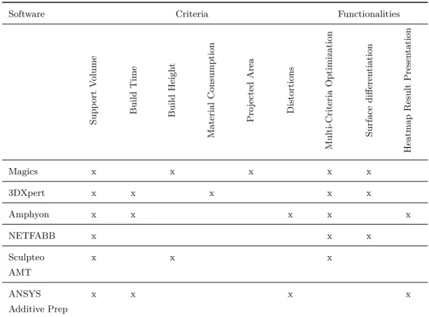
1.1 Criteria used by commercial part orientation software including specific functionalities . . . 46 2.1 Knowledge objects inferred from the literature part orientation in AM . 58 3.1 Geometrical operation and discretization of shape entities . . . 82 3.2 Local orientation desirability values for the cubic part example . . . 88 3.3 Comparing mean desirability values . . . 92 3.4 Comparison of different tessellation parameters for arithmetic mean . . 93 3.5 Comparison of different tessellation parameters for geometric mean . . 93 4.1 Summary of modeled action rules . . . 122 5.1 Turbine orientation problem responses . . . 130 5.2 Action rules weighting cases . . . 134 5.3 Maximum and minimum desirability values of aggregated responses . . 135 5.4 Minimum and maximum desirability values . . . 140 5.5 Comparison between ANSYS Additive Prep results and the desirability
approach results . . . 144 5.6 Comparison between ANSYS Additive Prep results and the desirability
approach results . . . 148 5.7 Valeurs de désirabilité locales pour l’exemple de pièce cubique . . . 177
Glossary
AHP: Analytical Hierarchy Process AM: Additive Manufacturing AR: Action Rule
CAD: Computer Aided Design
CAM: Computer Aided Manufacturing
COFFA: Design and Shape Optimization for Additive Manufacturing (FR: Con-ception et Optimisation de Forme pour la Fabrication Additive)
DF: Desirability Function
DMLS: Direct Metal Laser Sintering EBM: Electron Beam Melting
FDM: Fused Deposition Modeling KM: Knowledge Management MA: Manufacturability Analysis
NURBS: Non-Uniform Rational Basis Splines PBF: Powder Bed Fusion
SLA: StereoLithography Apparatus SLM: Selective Laser Melting
GLOSSARY 22
SLS: Selective Laser Sintering
STEP: STandard for the Exchange of Product model data STL: STereoLithography
Introduction
Thesis Context and COFFA Project
The question of product design customization has increasingly become a major concern for manufacturing industries that are facing an exigent demand. From the customer design specifications to the finished parts, the traditional methods of fabrication (milling, turning, casting, forging, etc) usually require the development of special individual tooling for each family of product. However, with the im-plementation of additive manufacturing (AM) and particularly the metal additive manufacturing methods such as the powder bed fusion (PBF), the development of new parts or assemblies has become faster. In the present industrial context, AM processes are gaining more and more importance thanks to their capability of pro-ducing various shapes from the simplest one to the most complex that were formerly difficult or impossible to manufacture with existing means. This large freedom in design made possible the development of more flexible design approaches such as the function based design (Klahn et al. (2015)), which allows generating products that are more competitive, lightweight and more suitable with their function. At their beginning, additive manufacturing technologies were limited to prototyping purposes, but nowadays they are extended to the manufacturing of end user prod-ucts (e.g. parts for automotive industry, medical implants, etc). Nevertheless, despite the advantages, the parts made with PBF systems recurrently suffer from issues related to quality and performance including lead time and cost (Metal AM Vol4, N°3, (2018)). The latter are actually causing production repeatability and reliability problems hindering the prompt progress of PBF techniques for some in-dustrial applications. Owing to the high cost of AM processes, products need to be well designed and well manufactured from the first time in order to alleviate the material waste.
Throughout the design process of a part, a designer must take advantage of 24
INTRODUCTION 25 the AM shape freedom, while taking into account the limitations related to the manufacturing resources. Today, the design based on topology optimization (TO), consisting of finding the right material distribution inside a given design space in order to meet targeted requirements: mass, stiffness etc (Costa et al. (2019)), is one the most popular approaches. However, either using classical CAD tools or TO tools, the designers as well as the manufacturing preparators or CAM opera-tors (those who adjust the manufacturing parameters) must consider the process constrains in order to make possible the right production from the first trial. Thus, they are confronted to recurrent decision making about the design and the man-ufacturing parameters. Today, this remains a complicated task since in AM not only little data about manufacturability criteria and indicators are available, but also, the commercial design solutions do not usually include the manufacturing constrains. Therefore, most of the industrial users, only rely on their knowledge (expertise). To leverage that expertise from the different actors of the value chain (design, preparation, manufacturing, post-processing) to assist the daily decision making, there is need of formalization and modeling tools.
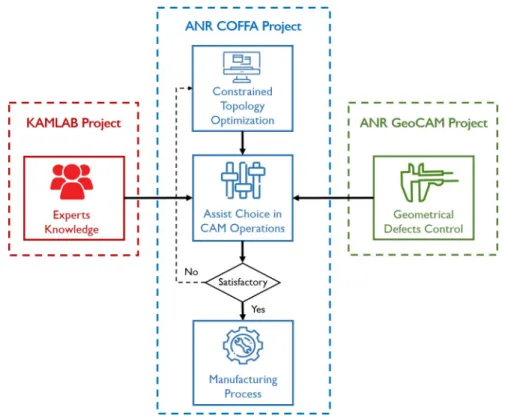
In the view of this, the COFFA project (Design and Shape Optimization for Additive Manufacturing) proposes to assist the actors along the value chain of AM by providing interactive CAD and CAM tools. This project funded by the french National Research Agency (ANR) gathers two laboratories namely G-SCOP (Grenoble INP) and I2M (ENSAM Bordeaux) both located in France. The scope of COFFA is limited to two powder bed fusion systems (electron beam melting EBM, and selective laser melting SLM). COFFA works in close collaboration as illustrated by Fig. 0.1 with KAMLAB project (Knowledge Aided Manufacturing) funded by DP Research Institute and the ANR GeoCAM project (Geometrical Control of parts produced by Additive Manufacturing) which is also led by I2M and G-SCOP laboratories. KAMLAB proposes a set of tools to acquire and formalize expert knowledge for manufacturing. GeoCAM studies the geometrical defects of powder bed fusion parts. In the present work, the results from these projects will be referred by the following references: Grandvallet et al. (2020) and Ghaoui et al. (2020).
The main objectives of COFFA are as follows:
1. The integration of manufacturing constrains in the topological optimization process – this part of the project aims at taking over some feasibility criteria early in the design stage.
INTRODUCTION 26
Figure 0.1: Collaborations between COFFA, KAMLAB and GeoCAM 2. The implementation of an automated surface reconstruction tool after
topol-ogy optimization in order to get geometrical entities as output.
3. The development of an approach to integrate experts knowledge in the as-sistance of the decision making on CAM parameters (manufacturing set of parameters comparisons for optimal choice).
4. The proposal of an approach to redesign parts by basing on the knowledge-based manufacturability assessment results.
For a given product to design and produce, the approach of COFFA is to first perform a topology optimization process including some manufacturing constrains. Secondly, the CAM parameters for manufacturing the part resulting from the topol-ogy optimization are determined based on experts formalized knowledge. Then, if the found set of manufacturing parameters are not satisfactory a re-topology optimization is achieved to solve the issues related to the geometry.
INTRODUCTION 27 This thesis will focus on the construction of a methodology to use as efficiently as possible the knowledge of experts in the PBF domain for supporting CAM decision-makers. The approach of this work is mainly centered on the assistance of the CAM actors in the choice of the right manufacturing parameters. The content of this document will discuss the methodologies and approaches executed to reach this objective.
The Powder Bed Fusion Process Chain and
Pre-processing Issues
PBF Techniques
In metal AM, Powder Bed Fusion (PBF) systems are today known as efficient ways to get end-user parts. They are based on the melting or sintering of powder layers by using the power of laser or electron beam. Three technologies namely the Direct Metal Laser Sintering (DMLS), the Selective Laser Melting (SLM) and the Electron Beam Melting (EBM) are dominating the market (Additive Manufacturing Market, web site 1). Fig. 0.2 shows a schematic description of the powder bed principle. Firstly, a rake spreads the powder in question on the build plate, then the beam melts or sinters the appropriate zones corresponding to the targeted shape. The possibility of handling thin layer thicknesses makes it possible to manufacture high resolution geometries and even very small features. A Swedish company company named ARCAM is the only manufacturer of EBM machines (Frazier (2014)), while a set of companies around the world are making SLM and DMLS machines such as SLM Solution, AddUp, Renishaw, Realizer, Concept Laser, EOS etc. This thesis focuses more on the EBM technology, nevertheless, most of the approaches that will be presented are also valid for SLM technology.
Value Chain & Pre-processing Issues
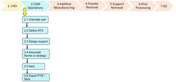
Owing to the technological shift between the traditional methods of manufacturing and the additive manufacturing, a significant difference can be noticed in the value chain of products acquisition. In AM, a product classically has to pass through several stages from its design to its quality control as shown in Figure 0.3 (taken from works of Grandvallet et al. (2020)). In the industrial practice, as well as in
INTRODUCTION 28
Figure 0.2: Powder bed fusion process
the academic research, these stages have been reported to be highly governing the production quality, repeatability and efficiency (Metal AM Vol4, N°3, (2018)).
For the PBF systems (similarly to the other AM techniques), the numerical chain begins with the design point, where the part’s shape is developed by design engineers based on specifications; the output is usually a CAD model in either native or standard formats. Today, two main design approaches can be used, namely the designer-driven shape (the shape is entirely made by the designer in a classical CAD environment) and the process-driven shape such as the TO (the shape generation is automated) (Hällgren et al. (2016)). Later on, the designed product is transferred to the pre-processing stage in which, the CAM operators adjust the manufacturing parameters and eventually suggest re-design options if non-conformance with the process capabilities occurs. The part is then processed by the PBF system and sent to the powder and support removal stages before engaging the post-processing in which, operations like finishing or polishing are achieved. Finally, a quality control is performed for the validation of customer requirements. All of these phases must be conveniently managed in order to obtain good quality products.
One of the pivot boxes making the interest of this thesis is the pre-processing of the parts, also known as CAM operations. It clusters different sub classes of operations to perform in order to adequate the designed geometry to the process and post-process specificities. The CAM operations mainly intend to setup the manufacturing parameters taking into account the limitations and intricacies of the available resources. Steps as orienting the part, defining the regions to support, designing the support structures, associating a build strategy and nesting (if more
INTRODUCTION 29
Figure 0.3: Powder bed fusion value chain and process preparation operations than one part) have to be managed in the CAM software.
• The part optimal orientation in the machine’s build space is one of the most important steps. Its determination is a complex task, which has significant impact on the product quality as well as on the build duration and cost (Pandey et al. (2007)). A particular attention will be given to this step in this document.
• The definition of the regions to support consists of detecting zones of an ori-ented part needing to be supported, these include the overhanging areas, and also zones that are likely to deform. In AM, support structures are currently used to anchor the part (Calignano (2014)) and help solving problems re-lated to the distortions of the products as well as avoiding the collapse of overhanging surfaces during the fabrication.
• Following the definition of regions to support, the support structures are designed by respecting a certain number of rules related to their height, distribution, density, fragmentation, etc. As the support structures do not belong to the targeted part, one must have in mind their removability while designing them.
INTRODUCTION 30 • The association of theme or strategy – allows defining volume attributes
which can be either porous or compact.
• Nesting step is usually required when different parts must be built at the same time. This operation is about finding an optimal way to position the parts relatively to each others, in order to maximize the quantity built si-multaneously, and thus reduce build time and cost.
• Exporting part to build allows storing and transferring the manufacturing required data containing for instance, the main geometry, the support struc-tures, the manufacturing parameters etc.
In spite of the scientific and technical advances, PBF products still exhibit a set of defects related to characteristics as geometry and strength (Frazier (2014)). The freedom in shape design offered by these technologies leads to think that every design can simply and successfully be materialized. In contrast, whatever the design method used, the geometry must comply with the capabilities of the manufacturing resources.
In the daily practice, for additive manufacturing, these are not trivial to take into account. On the one hand, the designer (in some cases, communicating with the manufacturing agents) might be able to analyze the feasibility for simple ge-ometries, but when the complexity increases, it becomes less and less realizable for him. On the other hand, the topology optimization process uses intricate al-gorithms in which it would be difficult to add all of the manufacturing constrains, as they have to be expressed mathematically and with some constrains such as derivability, continuity etc. Some of the manufacturing constrains are made up by the CAM operations to prepare stable manufacturing. The different CAM steps requirements might suggest re-design proposals so that the product returns to the designer with recommendations related to the manufacturability and eventually highlighting the problematic elements of the design. Setting up the CAM param-eters in additive manufacturing requires a certain level of skills about the process. From a study led by Grandvallet et al. (2017) alongside an industrial manufac-turer using PBF technologies, it can be seen that the CAM operators mainly use the know-how or expertise of their company when preparing parts. When formal-ized, this company expertise can be used to assist the determination of optimal manufacturing parameters that lead to the demanded quality, production cost and time.
INTRODUCTION 31
Research Question and Motivation
The formalized knowledge for CAM operations can be seen as rules that must be tested on a given geometry to check whether they are compliant or not and to what extent. For instance, CAM experts could recommend this rule for orienting a given part: “Orient the functional surfaces of the part close to the vertical”; in this case a good orientation of the part is the one that puts the maximum of its functional surfaces close to the vertical. This compliance assessment is not an easy task since, not only the geometries are usually complex in AM, but also the knowledge in its literal form is difficult to quantify. Moreover, if a couple of rules are considered, the complexity of the problem amplifies, making it difficult to handle manually. These requirements lead to a main question which is: How to Integrate the Experts Knowledge in the Assistance of CAM Operations for the Powder Bed Fusion Additive Manufacturing?
In this study (as detailed in Chapter 1), the investigation of the methods used for assisting CAM activities by using knowledge has shown that for PBF no solu-tion is available. For that reason those from tradisolu-tional manufacturing have been reviewed in order to check what can be adapted to the present need. The methods found mainly consist of inference engines, and they are usually based on feature recognition (decomposition of CAD parts) which is not suitable for the complex shapes involved in the additive manufacturing. A review of the knowledge types used by industry practitioners to select CAM parameters (presented in Chapter 2) has shown that action rules (e.g. “minimize the support marks on non-machined surfaces”) are mainly used. According to experts, the action rules are simulta-neously applied to see how extent they are compliant with the CAM parameters applied to the geometry of interest. For this reason, inference engines would not be suitable for the evaluation of the compliance level (quantitative values) of the action rules. At this time, it is difficult to find tools supporting this kind of eval-uation for additive manufacturing. The quantitative evaleval-uations pass through the mathematical representation of the rules. In regard of this, the central research question of this work is:
How to Mathematize Action Rules from Experts to Assist Decision-making in Powder Bed Fusion CAM operations?
One of the main aim of the present work is to fill the gap between rules, ex-pressed in natural language, and their evaluation on geometries regardless their complexity. A precedent work led by the same research team has gathered a set
INTRODUCTION 32 of useful knowledge resources about CAM for PBF systems (Grandvallet et al. (2017; 2017; 2020)). Following up, the present work aims at investigating a way to make use of that knowledge to support decision-making. This passes through being able to compare the scores (i.e manufacturability criterion) of multiple set of parameters.
Thesis Approach
According to what is aforementioned, different steps will be needed to respond to the research question. The points cited below describe the main approach of the present thesis.
1. Investigation of the methodologies used for computing part manufacturability in the traditional and additive manufacturing domains in order to find out which of them could help comply the present requirements.
2. Secondly, an investigation of the available formalized knowledge resources for AM CAM operations is performed. To this end, a brief review of the literature is carried out to find the already elicited knowledge and how, today, industry practitioners make use of that capitalized knowledge.
3. Construction of a novel modeling approach, which is able to transform formal-ized knowledge into mathematical models usable in computational systems. This constitutes the pivotal element to the transition from the literal nature of expressed knowledge to quantitative formulation.
4. Proposition of a method of assessing knowledge (in the form of rules) onto geometries. Beyond the modeling of knowledge, this work also aims at pro-viding a methodology to assess rules given by experts on geometries. This methodology must be able to handle any geometry from the simplest to the most complex one, and provide compliance level for each prescribed rule. 5. Design of decision making assistance tools in order to facilitate the analysis
of the results from the evaluations. The decision assistant intend to provide operators a scale to compare different scenarios of processing parameters.
INTRODUCTION 33
Manuscript Content
One of the major objectives of this work is to support the CAM activity in AM based on the formalized knowledge of the experts in the domain. To get to this, the knowledge has first to be acquired from experts through elicitation process, then formalized to infer action rules and finally translated from its literal form to something that can easily be evaluated on geometrical entities. The knowledge acquisition (elicitation) is not in the scope of this work, thus, knowledge resources available in the literature are used. Detailed analysis of all of these elements will be provided in the different chapters of this work. The document will thus be organized as follows:
Chapter 1 presents a review about pre-processing operations in PBF and part manufacturability assessment methodologies in traditional manufacturing and in additive manufacturing. Then, a discussion about knowledge leveraging methods in manufacturing pre-processing and their limitations is carried out.
Chapter 2 presents some of the knowledge typologies that can assist CAM as well as the type of knowledge that interests this work. This chapter will also inves-tigate the available knowledge resources in AM research literature and industrial practice for part orientation.
Chapter 3 proposes an approach to the quantitative modeling of a targeted knowledge type namely the Action Rules. Here, all the required stages allowing the transformation of the rules from literal to mathematical formulation (by using desirability functions) are discussed.
Chapter 4 exposes an application of the modeling approach to the computation of part orientation desirability. In this part, a set of rules from industry practition-ers about the good practices for orienting parts, are transformed into mathematical functions. The algorithms used for the evaluation of the rules on geometries are also presented for each action rule.
Chapter 5 presents the COFFA tool made for computing part orientation de-sirability. Here are also exposed a set of tools for decision making assistance and case studies of some industry parts.
Chapter 1
Review of CAM Systems & Use
of Knowledge for Assistance
Introduction
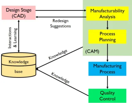
In the manufacturing domain, CAM systems have been used to ensure successful production for decades. Usually defined as numerical control programming tools (to generate toolpath), the CAM systems have today various meanings and usefulness. The different operations in CAM job intend to prepare the manufacturing process with the required parameters. Here, all the pre-processing steps between the design and the manufacturing stages are grouped in the CAM operations as depicted by Fig. 1.1. Preparing parts for manufacturing requires the selection of the best set of parameters that would allow getting optimal cost, production time and required quality. Hence, in order to reduce manufacturing cost due to useless iteration and time to market, decision making about those manufacturing parameters needs to be efficiently assisted. To do so, some tools are needed. Primarily, the comparison between scenarios (manufacturing parameters, design) is carried out on the basis of the feasibility or the so-called manufacturability evaluation. Then, a measure that can be qualitative or quantitative is used to benchmark and make strategic choice among different solutions.
Usually complex, manufacturability analysis (MA) task requires solid skills about the manufacturing system of interest. For this reason, the intervention of experts usually is vital to the achievement of those analyses as well as to the deci-sion making. Fig. 1.1 illustrates a kind of loop that many companies use to store feed-backs from CAM operations and quality control teams in the form of
CHAPTER 1. REVIEW OF CAM SYSTEMS & USE OF KNOWLEDGE FOR
ASSISTANCE 35
Figure 1.1: Classical scheme from design to manufacturing of components and manufacturing knowledge acquisition (adapted from Molcho et al. (2008))
edge resources (examples of quality knowledge extraction are available in Wang et al. (2007)). Those are most of times transformed into rules that can be used in future projects to design or analyze manufacturability (the present context). As said by Shukor and Axinte (2008), the manufacturing analysis systems offer various advantages such as:
• Recommending better designs, • Generating process sequences,
• Helping the selection of suitable parameters, processes and materials,
• Assisting designers lacking of in-depth knowledge about the process of inter-est.
In traditional manufacturing (including machining, casting and other techniques), various works have already been led to propose different manufacturability analysis methods or tools. They are usually based on rule bases arising from the capitalized
CHAPTER 1. REVIEW OF CAM SYSTEMS & USE OF KNOWLEDGE FOR
ASSISTANCE 36
knowledge. Comprehensive methods have been implemented into CAD/CAM algo-rithms for the traditional machining to evaluate the fitness of multiple parametric scenarios in order to generate re-design suggestions, process planning, process se-lection and materials (Sánchez et al. (1997), Capodieci et al. (2004)). In contrast, owing to its young age, in AM, not many tools intended to define manufacturing attributes based on expertise are available. It is then worth checking how knowl-edge has formerly been used in production in order to implement it as efficiently as possible to AM CAM. As a reminder, note that this thesis aims at proposing expertise-based assistance of parameter choice for AM.
In this brief review chapter, AM CAM operations as well as the concept of man-ufacturability analysis in traditional and additive manufacturing are investigated in sections 1.1 and 1.2 respectively. The section 1.3 will discuss the use of experts knowledge in the assistance of feasibility analysis.
1.1
Additive Manufacturing CAM Operations
The developers of new products must have in mind the restrictions and allowances of the downstream process that will be used for the elaboration of the products. That is the reason why every single step preceding the manufacturing process must be conveniently executed to ensure reliable production. In additive manufacturing numerical chain seems simple, but the steps inside require a particular attention. The design stage remains complex due the wide design space which is the con-sequence of the shape freedom. Hence, researchers concentrated many efforts on proposing design methodologies and standards of assistance for the various pro-cesses.
The AM CAM operations differ from those of the traditional manufacturing. The usual elements are the part orientation, the definition of the regions to support, the design of the support structures, the choice of the build strategy (not presented here) and the nesting. These operations have great impact on the production output. As stated by Arndt et al. (2015), the only prerequisite to the economically feasible utilization of AM technologies is the best manufacturing preparation. In the following sub-sections these pre-processing operations are detailed.
CHAPTER 1. REVIEW OF CAM SYSTEMS & USE OF KNOWLEDGE FOR
ASSISTANCE 37
1.1.1
Part Orientation
This operation opens the pre-processing steps. It has been seen as one of the activities that have the greatest impact on the manufactured part geometrical and mechanical qualities. The orientation of the parts can be defined by two angles α and β in the global reference (o, x, y, z) as illustrated in Fig. 1.2. And those two parameters alone can have a huge impact on the desired process duration (thus, the time to market), the quality expected by the customers and the production cost Köhler (2009). Today, it is well known that all of the downstream CAM steps depend on the build orientation. Hence, ensuring the product’s conformity starts by defining the right orientation.
Figure 1.2: Example of part orientation definition
However, optimally defining the handles α and β, requires a certain level of skills about the AM system of interest (Grandvallet et al. (2020)). In PBF systems such as electron beam melting, things are even more complicated cause of the process specificities. Another issue in AM is that the criteria for orienting parts largely vary from one process to another. For instance in FDM, it is usually preferable to orientate the part such that its largest flat surface is in contact with the building plate to ensure the process stability (Hur and Lee (1998)). In contrast, for EBM, the engineer should better avoid large horizontal melted areas in order to prevent the part from geometrical distortions (Danjou and Köhler (2009)). Moreover, the
CHAPTER 1. REVIEW OF CAM SYSTEMS & USE OF KNOWLEDGE FOR
ASSISTANCE 38
stability in EBM process is by default ensured by the surrounding powder in the machine vat.
Despite the advances made, existing pre-processing tools do not still fully assist operators in the choice of convenient orientation where experts are not available to intervene. Based on the investigations achieved here, no tool including expert knowledge in the determination of α and β has been found. From the works led by Grandvallet et al. (2020), it can be clearly seen that in the industrial context, people have many good practices and it is possible to formalize rules arising from their daily activity. Particular specifications can be found in that work. For instance, they differentiated the different surfaces of the part and classified them into categories. Among those are the post-machined surfaces, the priority surfaces and the machining datum surfaces. Each class of surface must be oriented in a specified way according to the experts. The governing rules are not simple to evaluate on complex geometries. So far, none of those kind of rules are integrated in software or algorithms to solve orientation problems; this is of great need and requires research efforts.
1.1.2
Definition of Regions to Support
Owing to the orientation, there might be some surfaces of a geometry that directly rely on the powder during the manufacturing. Those surfaces need to be supported during the layer by layer stacking. Support structures have multiple functions. They can play the role of heat sink (Järvinen et al. (2014)) especially in metal fusion, where heat rate is relatively high. They also play the role of anchors that hold the part to prevent from distortions (Hussein et al. (2013), Bobbio et al. (2017)). Defining regions to support is an important step in AM. For example, in EBM it is not recommended to start melting material directly over the powder (this can cause dross effects as described in Calignano (2014)), thus support structures are needed. Today, the criterion mainly used to define regions to support (on surfaces) is the overhanging, which is governed by the angle of the surface from the horizontal. However, one should go further in considering criteria such as support removability or their ability to mechanically stand process induced mechanical stresses due to temperature gradient during solidification.
CHAPTER 1. REVIEW OF CAM SYSTEMS & USE OF KNOWLEDGE FOR
ASSISTANCE 39
1.1.3
Design of the Support Structures
Designing support structures involves complex criteria linked with their distribu-tion, density, shape, orientadistribu-tion, required resistance and so on. They have to be robust enough to absorb the thermal stresses, and soft enough to be post-processed. A common practice is to connect the support and the main body with spaced teeth (Fig. 1.3); this eases the removal. Authors have proposed in some ways, algorithms or methodologies to help the strategic design of support structures. Calignano (2014) worked on the optimization of the supports to reduce manufacturing and post processing efforts in SLM technologies. He used Taguchi’s method to exper-imentally determine which topology of support would prevent from warping and would be easy to break.
Figure 1.3: Support teeth and perforation
As a result teeth dimensions, perforation type and other geometrical specifi-cation could be proposed. Vaidya and Anand (2016) proposed a way to optimize support made of unit cells of various geometries (that can be hollowed) distributed by using Dijkstra’s shortest path algorithm.
In order to ensure the efficient thermal conduction of the support structures, Zhou et al. (2019) reported an optimization approach for laser PBF. They imple-mented a transient heat transfer model into a gradient-based topology optimization to find the convenient material distribution. Additionally, to also ensure support’s resistance, some authors investigated their mechanical strength for powder bed fusion (Bobbio et al. (2017)). Although commercial tools for automated support generation exist (e.g. Amphyon by Additive Works), some practitioners still prefer achieving support design semi-manually using tools as Magics (by Materialise).
CHAPTER 1. REVIEW OF CAM SYSTEMS & USE OF KNOWLEDGE FOR
ASSISTANCE 40
1.1.4
Nesting
When making multiple parts, it is better to find a way to maximize the number of components in the production batches in order to minimize time to market and extra costs. Indeed, for powder bed fusion techniques the time to prepare the machine (fill the powder tank, calibrate the plate, make vacuum if needed, and preheat the chamber) is not negligible and must be achieved for each new production batch. To avoid repeating these setup times, an efficient way is the nesting optimization, which allows putting as many parts as possible in the build space. A nesting method combined with production scheduling has been proposed by Chergui et al. (2018) for electron beam melting. Different methodologies are available in the literature (Canellidis et al. (2013), Wang et al. (2019), Wodziak et al. (1994)).
It has to be kept in mind that the nesting needs to be operated with consid-eration of some important points such as guarantying the optimal orientation. In this context, Zhang et al. (2015) worked on a parallel nesting scheme based on 2D projection profiles. They first find out the optimal orientations for each part by using feature-based method, then, they used a parallel layout searching algo-rithm to determine the best projected 2D layout. For further efficiency, Arndt et al. (2015) worked on three dimensional nesting that also examines the optimal orientation of each part in the build space. For these methods, various commercial solutions are being developed since the additive manufacturing market is facing a fast economical growth.
1.2
Manufacturability Analysis
Faced with a more and more pressing demand and a strong competition, compa-nies have to reduce manufacturing costs, leading times and provide good quality products. To achieve this, products must be compliant from the first production attempt to avoid time useless consumption and material waste i.e. their manufac-turability has to be ensured starting from the design stage. For this reason, the concept of DFM has been largely used over the last decades to tackle the feasi-bility issues due to the gap between the designed and the manufactured products Shankar and Jansson (1993), Gupta and Nau (1995), Sánchez et al. (1997). In the classical scheme of manufacturing companies, the product designers do not have much information about the capabilities of the available machinery, and do not have enough feed-backs from the manufacturing teams (Ong and Chew (2000)).
CHAPTER 1. REVIEW OF CAM SYSTEMS & USE OF KNOWLEDGE FOR
ASSISTANCE 41
Thus, during the product development life cycle, many iterations are performed to finally determine the best feasible design (Shukor and Axinte (2008)). This has justified the need of developing manufacturability analysis systems that allow matching the design requirements with the manufacturing process properties. In next sub-sections, reviews of some MA methods in traditional and additive manu-facturing are presented.
1.2.1
In Traditional Manufacturing
The manufacturability analysis can either be introduced in the design or the pre-processing operations. In either situation product modifications can be carried out. For example, for a molded part, the designer has to take account of the parting line of the mold to make possible the extraction. Nevertheless, as mentioned, the inclusion of all constrains is not always possible during the design stage. The concept of manufacturability does not only involve the designed shape but also the manufacturing parameters fitness which have a high impact; sometimes the issues are simply covered by setting up the right process parameters. In traditional manufacturing systems works have been led for decades to implement a variety of manufacturability analysis tools. Gupta et al. (1997) stated that the three main characteristics that differentiate the manufacturability systems are the approach used, the measure of manufacturability used and the level of automation.
According to the review of Shukor and Axinte (2008), the most commonly used manufacturability analysis systems are made of expert systems. They can be based on fuzzy logic, neural networks, rule-based systems (RBS), object oriented techniques, agent-based systems or analytical hierarchy process (AHP). Among the latter, the rule-based systems are likely the most used (Shukor and Axinte (2008)). These systems fully rely on inference engines consisting of IF/THEN rules applied in a procedural manner (Brissaud and Tichkiewitch (2000)) using logical units (and, or). Chan (2003) reported an ES tool evaluating manufacturability regarding the selection of processes and materials and the production cost estimation. That tool also assist designers through design recommendations. Other examples can be found in the works of Kusiak and Chen (1988), ...
Object oriented techniques are the second most used expert systems (Shukor and Axinte (2008)). In this technique different objects are used to represent the model entities. Each of them contains classes which in turn have other sub-classes and the relationships between them are clearly defined. The objects contain the necessary data and their programming codes as well. Some Illustrations of the
CHAPTER 1. REVIEW OF CAM SYSTEMS & USE OF KNOWLEDGE FOR
ASSISTANCE 42
use of such systems are presented in Horvath et al. (1999), Amalnik and McGeough (1996), Giachetti and Alvi (2001), etc.
Following this, the analytical hierarchy process is the third most used method Shukor and Axinte (2008). Analytical hierarchy process is used to assign weighting factors to the features composing a part in order to take account of their impor-tance degree. Ong and Chew (2000) developed a machinability and fixturability evaluation system including a solid modeler and databases containing information about available manufacturing operations, tools, dimensional constraints and pro-cess capabilities. The quantitative evaluation of the manufacturability is made on the basis of different metrics related to geometrical attributes (orientation, in-tricacy, accessibility) and technological attributes (dimensional tolerance, surface finish, etc). They used analytical hierarchy process to combine all the individual metrics into an overall one.
The fuzzy logic based expert systems are usually implemented in a hybrid way. In fact, they combine with the RBS, AHP or neural network systems to facilitate the analysis and decision making process. For instance, Korosec et al. (2005) quan-titatively fuzzified machine-technological and geometry-topological parameters in order to evaluate the feasibility by using fuzzy evaluation function based on neural networks. The latter allowed representing the complex inter-relations between the fuzzified feature parameters. As a result, intricacy index is proposed. Ong et al. (2003) also proposed a fuzzy set AHP-based design for manufacturability tool for rotational parts. The fuzzy-based system was used to calculate manufacturability indices regarding part support, clamping and its features. The analytical hierarchy process allowed assigning weights to the features with respect of their importance. Agent-based systems use different agents that can concurrently reason to make de-cision (Shiau et al. (2000)). For example, design agent (used to refine the design) and manufacturing agent (used to choose process parameters) can be used to co-operate. Medani and Ratchev (2005) reported an early design manufacturability assessment method using collaborative agents to support the design, process plan-ning and facility activities assignment. Each agent has an XML ontology behind to communicate with databases dedicated to its activity.
Globally, in the traditional manufacturing systems, the manufacturability anal-ysis is mainly centered on a feature-based design interpretation (Gupta et al. (1997)). Indeed, the considered geometry is decomposed into basic geometries to make the correspondence with predefined sample features proper to a given process (Salomons et al. (1993), Gao et al. (2004)). For instance, to analyze the manufac-turability of the component in Fig. 1.4 it is broken down into simple entities; then,
CHAPTER 1. REVIEW OF CAM SYSTEMS & USE OF KNOWLEDGE FOR
ASSISTANCE 43
Figure 1.4: Example of geometry decomposition – feature recognition the manufacturability of each feature is evaluated separately.
The evaluation or measure can be of three distinct types: binary, qualitative or quantitative. In the binary approach the design can only be feasible or not fea-sible regarding the capabilities of a given process (Sánchez et al. (1997)). For the qualitative methods, grammatical concepts such as “good”, “poor” or “average” are used to rate the manufacturability of a given design. The quantitative meth-ods aim at providing a manufacturability index allowing a user to easily perform comparisons, or an optimization system to find optimum solutions. The present study will particularly focus on quantitative evaluations of manufacturability.
1.2.2
In Additive Manufacturing
In AM, the freedom in shapes generation leads to believe that all geometries are manufacturable while there are restrictions inherent to the processes. Unfortu-nately, the designed geometry which looks perfect in the CAD software, comes out with different types of defects. Solving these issues either requires modifying the design or setting the right manufacturing parameters and sometimes both of them. So far, different authors attempted to provide design guidelines to help en-suring producible parts, in other words design for additive manufacturing methods (Kranz et al. (2015), Adam and Zimmer (2014), Laverne et al. (2015), Teitelbaum et al. (2009), Vayre et al. (2013), Vaneker (2017)). A few studies based on some of