HAL Id: tel-02108253
https://tel.archives-ouvertes.fr/tel-02108253
Submitted on 24 Apr 2019
HAL is a multi-disciplinary open access
archive for the deposit and dissemination of sci-entific research documents, whether they are pub-lished or not. The documents may come from teaching and research institutions in France or abroad, or from public or private research centers.
L’archive ouverte pluridisciplinaire HAL, est destinée au dépôt et à la diffusion de documents scientifiques de niveau recherche, publiés ou non, émanant des établissements d’enseignement et de recherche français ou étrangers, des laboratoires publics ou privés.
structures
Peng Wang
To cite this version:
Peng Wang. Active vibration control in a specific zone of smart structures. Other. Université de Lyon, 2019. English. �NNT : 2019LYSEC007�. �tel-02108253�
THÈSE DE DOCTORAT DE L’UNIVERSITÉ DE LYON
opérée au sein de
l’Ecole Centrale de Lyon
Spécialité: “Automatique”
préparée dans le laboratoire Ampère et LTDS
dans le cadre de l’École Doctorale EEA de Lyon (ED160)
par :
Peng WANG
Active vibration control in a
specific zone of smart structures
Soutenue publiquement le 25 Mars 2019 devant le jury composé de :
Rapporteur M. Gilles Duc Professeur, CentraleSupélec
Rapporteur M. Jean-François Deü Professeur, Conservatoire National des Arts et Métiers Présidente Mme. Isabelle Queinnec Directeur de Recherche, CNRS, LAAS
Examinatrice Mme. Emeline Sadoulet Maître de Conférences, Université de Franche Comté Encadrant M. Manuel Collet Directeur de Recherche, CNRS
Encadrant M. Xavier Bombois Directeur de Recherche, CNRS
Encadrant M. Anton Korniienko Maître de Conférences, École Centrale de Lyon Directeur de thèse M. Gérard Scorletti Professeur, École Centrale de Lyon
This dissertation is the conclusion of my three-year researches at the Laboratoire Ampère of École Centrale de Lyon (ECL) and the department of Laboratoire de Tribologie et Dynamique des Systèmes (LTDS). I am deeply indebted to a number of people without whose encouragement and assistance I would not have accomplished my researches. Now it is my pleasure to express my sincere grati-tude to them all.
My deepest gratitude goes first and foremost to my superiors, Professor Gérard Scorletti, Director Manuel Collet, Director Xavier Bombois and Doctor Anton Korniienko for their constant guidance and invaluable supports throughout my researches in ECL. Professor Gérard Scorletti have guided me with illuminating instruction and expert advice. He always explains the knowledge and responds to my questions with great patience. His extensive knowledge, rigorous attitude of scholarship and open mind deeply influence me. Director Manuel Collet gives me great help and support on the modeling work and provides me with very useful experimental guidance. Without his help, I would not have obtained reliable models and satisfactory experimental results. Director Xavier Bombois gives me great instruction and help on the identification technique which greatly contributes to the success of my research. I also owe a special debt of gratitude to him for helping me redact and revise my article. Doctor Anton Korniienko gives me great assistance during my researches on robust control. We are like friends. I want thank him first for representing me to conduct the presentation at the conference in Brazil. And also thank him for inviting me to his home and experiencing a perfect dinner.
I would also like to thank the members of LTDS and Ampère for providing an enjoyable working environment of mutual interest in each others’ researches in which many problems could be discussed and solved. Especially to Dr. Kaijun Yi, Doctor Ellen Skow, Kévin Colin, Daumas Amaury, Chuhan WANG for their sincere help to my work.
On a more personal note, I would like to thank my parents and my wife for their love, care, help and encouragements over these years. Without their supports, I would not have gone so far. Thank them for always being so supportive despite my choices in life.
At last, I gratefully acknowledge Chinese Scholarship Council (CSC) for provid-ing the fundprovid-ing source and for supportprovid-ing my doctor work.
This research aims at solving a particular vibration control problem of smart structures. We aim at reducing the vibration in a specific zone of the smart structure under the disturbance that covers a wide frequency band. Moreover, at this specific zone, neither actuation nor sensing is possible.
Here we face several main challenges. First, we need to control the vibration of a specific zone of the structure while we only have access to measurements at other zones. Second, the wide bandwidth of the disturbance implies that numerous modes should be controlled at the same time which requires the use of multiple actuators and sensors. This leads to a MIMO controller which is difficult to obtain using classical controller design methods. Third, the so-called spillover problem must be avoided which is to guarantee the closed-loop stability when the model-based controller is applied on the actual setup. To tackle these challenges, we investigate two control strategies: the centralized control and the distributed control.
For centralized control, we propose a methodology that allows us to obtain a sim-ple MIMO controller that accomplishes these challenges. First, several modeling and identification techniques are applied to obtain an accurate low-order model of the smart structure. Then, an H∞ control based synthesis method with a particularly proposed H∞ criterion is applied. This H∞criterion integrates mul-tiple control objectives, including the main challenges. In particular, the spillover problem is transformed into a robust stability problem and will be guaranteed using this criterion. The obtained H∞ controller is a standard solution of the
H∞problem. The final controller is obtained by further simplifying this H∞ con-troller without losing the closed-loop stability and degrading the performance. This methodology is validated on a beam structure with piezoelectric transducers and the central zone is where the vibration should be reduced. The effectiveness of the obtained controller is validated by simulations and experiments.
For distributed control, we consider the same beam structure and the same con-trol objectives. There exist methods aiming at designing distributed concon-trollers of spatially interconnected system. This research proposes a FEM based method, combined with several model reduction techniques, that allows to spatially dis-cretize the beam structure and deduce the state-space models of interconnected
subsystems. The design of distributed controllers will not be tackled in this research.
Cette recherche vise à résoudre un problème particulier de contrôle de vibration. L’objectif est de réduire les vibrations dans une zone spécifique de la structure intelligente avec une perturbation qui couvre une large gamme de fréquences. De plus, dans cette zone spécifique, ni l’actionnement, ni la mesure ne sont possibles. Ici, nous faisons face à plusieurs défis principaux. Premièrement, nous devons contrôler les vibrations dans une zone spécifique, alors que nous n’avons accès aux mesures que dans d’autres zones. Deuxièmement, la large bande passante de la perturbation implique que nombreux modes doivent être contrôlés en même temps, ce qui nécessite l’utilisation de plusieurs actionneurs et capteurs. Cela conduit à un contrôleur MIMO difficile à obtenir pour les méthodes classiques de conception. Troisièmement, il faut éviter le problème de spill-over, qui consiste à garantir la stabilité en boucle fermée lorsque le contrôleur basé sur un modèle est appliqué à l’installation réelle. Pour relever ces défis, nous étudions deux stratégies de contrôle : le contrôle centralisé et le contrôle distribué.
Pour le contrôle centralisé, nous proposons une méthodologie qui nous permet d’obtenir un contrôleur MIMO simple. Tout d’abord, plusieurs techniques de modélisation, de réduction et d’identification sont appliquées pour obtenir un modèle précis d’ordre faible de la structure. Ensuite, une méthode de synthèse basée sur le contrôle H∞ avec un critère H∞ particulière est appliquée. Ce critère H∞ intègre plusieurs objectifs de contrôle, y compris les défis principaux. En particulier, le problème de spill-over se transforme en un problème de stabil-ité robuste et sera garanti en utilisant ce critère. Le contrôleur H∞ obtenu est une solution standard du problème H∞. Le contrôleur final est obtenu en sim-plifiant ce contrôleur H∞ sans perdre la stabilité en boucle fermée ni dégrader les performances. Cette méthodologie est validée sur une structure de poutre avec des transducteurs piézoélectriques et les vibrations dans la zone centrale doit être réduites. L’efficacité du contrôleur est validée par des simulations et des expériences.
Pour le contrôle distribué, on considère la même structure et les mêmes objectifs. Il existe des méthodes visant à concevoir des contrôleurs distribués pour les sys-tèmes spatialement interconnectés. Cette recherche propose une méthode basée
sur la FEM, associée à plusieurs techniques de réduction de modèles, permettant de discrétiser spatialement la structure de la poutre et d’en déduire les modèles d’espace d’état des sous-systèmes interconnectés. La conception des contrôleurs distribués n’est pas abordée dans cette recherche.
Contents
Nomenclature xii
I
Dissertation
1
1 Introduction 3
1.1 Motivation of this research . . . 3
1.2 Approaches of this research . . . 6
1.3 Publications . . . 8
1.4 Organization of this dissertation . . . 8
2 Background 11 2.1 Smart materials for active vibration control . . . 11
2.2 Active vibration control of flexible structures . . . 13
2.3 Distributed control of flexible structures . . . 16
2.4 Summary . . . 18
3 System description 19 3.1 Experimental setup . . . 19
3.2 Control objectives and considerations . . . 22
3.3 Centralized controller implementation . . . 24
3.4 Methodology overview for centralized controller design . . . 26
3.5 Overview of modeling for distributed control . . . 28
3.6 Summary . . . 29
4 Modeling for centralized control 30 4.1 State-space modeling of beam-piezo system . . . 31
4.1.1 Governing equation deduced with COMSOL . . . 32
4.1.1.1 Finite Element Modeling . . . 32
4.1.1.2 Modal decomposition and truncation — Modal Displacement Method . . . 33
4.1.1.3 Piezoelectric capacitance correction — Static cor-rection . . . 35
4.1.2 Damping effect . . . 36
4.1.3 Measurement circuit . . . 37
4.1.4 Determination of the central energy . . . 38
4.1.5 State-space representation . . . 39
4.1.6 Application to the experimental setup . . . 41
4.2 Model improvement using Grey-box identification . . . 42
4.2.1 Grey-box identification theory . . . 43
4.2.2 Grey-box optimization of the beam-piezo system model . . 45
4.2.3 Application . . . 47
4.3 Multi-variable model reduction . . . 51
4.3.1 Overview of model reduction methods for mechanical struc-tures . . . 51
4.3.2 The proposed method . . . 52
4.3.3 Modal form truncation . . . 53
4.3.4 Relative error minimization . . . 54
4.3.4.1 Relative error selection . . . 55
4.3.4.2 Formulation and solution of the minimization prob-lem . . . 58
4.3.5 Application to the beam-piezo system model . . . 64
4.4 Summary . . . 67
5 Centralized controller design 69 5.1 H∞ control approach . . . 69
5.1.1 Performance and criterion . . . 70
5.1.2 Robust stability . . . 73
5.2 H∞ controller design for the vibration reduction in the central zone 74 5.2.1 Vibration reduction problem statement . . . 74
5.2.2 Augmented system and control criterion . . . 75
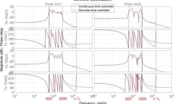
5.2.3 Controller reduction and discretization . . . 81
5.2.4 Application to the beam-piezo system . . . 82
5.2.4.1 Augmented system . . . 82
5.2.4.2 Weightings and results . . . 83
5.2.4.3 Reduced-order controller . . . 86
5.2.4.4 Performance — Central energy reduction rate . . 86
5.2.4.5 Numerical simulation . . . 88
5.3 Experimental validation . . . 89
5.4 Discussion in single-variable case — Limitation of SISO controllers 94 5.5 Summary . . . 96
6 Modeling for distributed control 98 6.1 Distributed modeling overview . . . 99
6.2.1 Guyan condensation . . . 101
6.2.2 Euler-Bernoulli kinematic assumption . . . 102
6.3 Application to the structural cells . . . 104
6.3.1 Cells with piezos . . . 105
6.3.1.1 Simplified governing equation . . . 105
6.3.1.2 COMSOL solutions . . . 109
6.3.2 Homogeneous cells . . . 111
6.3.3 Assembly . . . 111
6.4 State-space modeling of interconnected LTI subsystems . . . 115
6.4.1 Discussions . . . 116
6.4.2 Architecture of the interconnected system . . . 117
6.4.3 Construction of LTI subsystems . . . 120
6.5 Appendix . . . 126
6.6 Summary . . . 138
7 Conclusions and future research 141
II
Résumé en français
144
1 Introduction 146 1.1 Motivation de cette recherche . . . 1461.2 Contexte . . . 148 1.3 Organisation de la thèse . . . 150 2 Description du système 151 2.1 Installation expérimentale . . . 151 2.2 Objectifs et considérations . . . 153 2.3 Implémentation du contrôleur . . . 154 3 Contrôle centralisé 156 3.1 Méthodologie . . . 156 3.2 Modélisation. . . 157 3.3 Correction du modèle . . . 160
3.4 Réduction du modèle multi-variable . . . 161
3.4.1 Troncature de la forme modale . . . 162
3.4.2 Minimisation de l’erreur relative . . . 163
3.4.3 Application . . . 164
3.5 Conception du contrôleur par contrôle H∞ . . . 165
3.5.1 Cahier des charges . . . 165
3.5.2 Critère H∞ . . . 166
3.5.3 Réduction et discrétisation du contrôleur . . . 169
4 Modélisation pour le contrôle distribué 173
4.1 Modélisation des cellules . . . 173
4.1.1 Condensation de Guyan . . . 175
4.1.2 Hypothèse cinématique d’Euler-Bernoulli . . . 175
4.1.3 Application . . . 176
4.2 Modélisation des sous-systèmes . . . 177
5 Conclusions et recherches futures 182
A PZT selection 183
B Construction of the weighting for robust stability 186
Nomenclature
Symbols
Mmode Normalized mass matrix
Kmode Stiffness matrix relating to Mmode
Xmode Damping term relating to Mmode
E Electromechanical coupling coefficients relating to Mmode
Ea Electromechanical coupling coefficient of actuators
Es Electromechanical coupling coefficient of sensors
F External force vector relating to Mmode
R Capacitance matrix
Rc Corrected capacitance matrix
Rs Sensor capacitance matrix
ri Capacitance of the ith PZT pair
Q Electrode charge vector of PZT pairs
Qs Electrode charge vector of PZT pairs used as sensors
V Voltage vector of PZT pairs
Va Voltage vector of PZT pairs used as actuators
Vs Voltage vector of PZT pairs used as sensors
f Force disturbance
ϕ Eigenfunction
η Modal coordinate
ωi Natural frequency of the ith mode
νnode Velocity vector of the nodes in the central zone
κa Viscous air damping constant
κs Strain-rate damping constant
Y Internal impedance of the control board
Ys Impedance matrix
Ecent Central energy
Ecentp Proportional central energy
Gf ull Full-order model
Gr Reduced-order model
P Augmented system
K To-be-designed controller
Kred Reduced-order controller
Ω Frequency band of interest
rp
e Proportional central energy reduction rate
ρ Density of the beam material
Yang Young’s Modulus
∆ Uncertainty or modeling error
Md System with no uncertainty (nominal system)
Ts Sampling time
Λ(A) Eigenvalues of a matrix A
Gu→y Open-loop transfer function from input u to output y
Tu→y Closed-loop transfer function from input u to output y
Su Power Spectrum Density (PSD) of a signal u
diag (A1, A2, ..., An) Diagonal or block-diagonal matrix
with Ai, i = 1, 2, · · · , n the diagonal terms or blocks
AT Transpose of a real matrix A
A∗ Conjugate transpose of a complex matrix A
s(t) Time domain average value of the real-time signal s(t) ||G||2 H2 norm of an LTI system G
||G||∞ H∞ norm of an LTI system G
σ(T (jω)) Maximal singular value of transfer function T (jω)
? Redheffer star product
Acronyms
PZT Lead Zirconate Titanate
LTI Linear Time Invariant
PPT Positive Position Feedback
LQR Linear Quadratic Regulator
LQG Linear Quadratic Gaussian
MIMO Multi Input Multi Output
PSD Power Spectrum Density
MFT Modal Form Truncation
LMI Linear Matrix Inequality
DAC Digital-to-Analog Converter
ADC Analog-to-Digital Converter
FEA Finite Element Analysis
FEM Finite Element Modeling
Dissertation
Chapter 1
Introduction
This chapter introduces the motivation of this work. Then the objectives and the approaches are briefly discussed. Finally, an overview of the remaining chapters is presented.
1.1
Motivation of this research
Lighter structures and flexible manipulators have increasingly attracted atten-tions for many applicaatten-tions in many industrial domains (aerospace industry, au-tomotive industry, manufacturing industry, etc.). The main advantages of light structures are their light weight and low production cost. With the develop-ment of more advanced technologies and materials in industry, it is possible to implement lightweight components in practice for miniaturization and efficiency especially in aerospace and automotive domain. However, light weight compo-nents are generally less rigid which makes the structure more flexible. This is reflected by a relatively small structural damping. Such flexible structure may suffer from considerable vibrations when they are excited by external distur-bance around the resonant frequencies. The excessive vibrations problem will lead to unpleasant noises, unexpected stress, positioning error, material fatigue, malfunction, or even structure failure. Consequently, effectively controlling the vibrations in such structures is an objective of crucial economic importance which has motivated a huge amount of research in this field [1–4].
For the vibration control of flexible structures, passive vibration control first gained popularity in practical applications because of its practicability and reli-ability for example in [5–7]. As an alternative way, active vibration control [8] have drawn lots of attention in recent years. Different from passive vibration control methods where the control mechanisms work as the vibration absorber, active vibration control methods generally use a set of actuators and sensors (ac-tive structures) connected by a feedback loop. In this case, we exploit the main advantage of feedback which allows us to reduce the sensitivity of the output to parameter variations and to attenuate vibration disturbance within the band-width of the control system. Depending on the circumstances, active structures may be cheaper or lighter than passive structures (structures with passive control machenisums) of comparable performances and they may offer performances that no passive structure could offer [9]. This is possible because we can provide the control mechanisms with external energy to counteract more with the structural vibration.
Nowadays, active vibration control methods are becoming more and more cost efficient due to rapid development of electronic technologies which makes actua-tors and sensors more intelligent and efficient. We call such actuaactua-tors and sensors the smart materials, such as piezoelectric materials, magnetostrictive materials, magneto-rheological, etc. Smart structures thus refer to the active structures integrated with such smart materials (used as actuators and sensors). A large part of the researches concerning the active vibration control of smart structures has used piezoelectric materials for actuation and sensing [10] because of the high precision and performance. Piezoelectric actuators have proven to be very useful in suppressing vibration and shape control of flexible structures [11–16]. Our objective is to design proper feedback controller to tackle a particular vibration problem on such smart structures (active vibration control) as explained bellow. The active vibration control problem studied in this work has its particularities which reflect particular applications mainly in aerospace and automotive domain. First, the vibration energy must be particularly rejected in specific locations. For example, at the location of an antenna or a sensor on the aircraft envelope, at the location of the passenger’s seat in a car (see Fig.1.1), etc. In other words, we aim at focusing the control effort on specific locations. This allows us to achieve particular objectives for example giving more comfort to the passengers in a car. Second, we cannot place actuators or sensors at these specific locations. As there
are already multiple devices connecting with each other at these specific locations, it will thus be difficult to add extra actuation and sensing devices. The challenge will be to reduce the vibration in specific locations while only have access to the vibration state at other locations. This challenging objective requires the use of modern multivariable control design methods which allows us to tackle unmeasured performance variables. Third, we aim at reducing the vibration in a frequency band as wide as possible. All control systems have limited working bandwidth. The wider the bandwidth is, the more applicable the system will be. Fourth, the designed controller must avoid the so-called spill-over problem [17] which is the instability caused by the neglected model dynamics when the model-based controller is applied on the actual setup. As it will be discussed in the sequel, this spillover problem will be studied as a robust stability problem.
Figure 1.1: Examples of applications for particular vibration control problems
To reproduce the above vibration problem, we build an experimental setup which is composed of a free-free aluminum beam where a number of smart materials (here we use piezoelectric transducers) have already been patched except in the central zone of the beam. Details for this setup will be introduced in the sequel. A certain set of piezoelectric transducers will be used as sensors and another set as actuators. The objective is to compute feedback controllers that reduce the vibration energy in the central zone. In this research, we will first pro-pose a methodology that allows us to design a satisfactory centralized controller. Then, considering the complexity of a centralized controller and its inconvenient physical connections, we then turn to distributed control. This research gives a modeling method for interconnected subsystems of the considered structure which will, in the future, allow us to synthesis distributed controllers.
1.2
Approaches of this research
The method proposed in this research is a model-based controller design process. We need a simple and accurate model of the structure and an efficient synthesis algorithm to compute the controller that achieves all the above objectives. The approaches used in this research is summarized as follows.
For centralized control, we propose a methodology which is the combination of several techniques that will finally lead to a satisfactory controller with guaran-teed performance on the actual setup. First, we will build a mathematical model of the considered structure. As far as researches on active vibration control of flexible beams, most of the control design techniques make use of approximated finite-dimensional models [10] deduced using Finite Element Modeling (FEM) techniques [18–24]. FEM gives us the so-called governing equation (a partial differential equation) that contains the dynamics of the beam and the electrome-chanical coupling between the piezoelectric transducers and the beam. This modeling process can be done using commercial software that performs Finite Element Analysis for example ANSYS [25] and COMSOL [26]. Many researches use such software to build the model of the structure for active vibration control, see [20, 24] for ANSYS and [21, 22] for COMSOL. We here use COMSOL to perform Finite Element Analysis based on standard 3D elements which allows us to tackle the coupling effect between the beam and the piezoelectric trans-ducers. However, the resulting governing equation will have a large number of Degree of Freedom (DOF) which is too complex for controller design. In this work, we apply Modal Displacement Method [27] which allows us to decompose the displacement field into modes and approximate the global behavior of the initial governing equation by a simpler one which neglects the higher frequency modes. The error introduced by this neglection is also corrected using the Static correction [28]. Finally, this governing equation is transformed into a state-space model. One of its outputs is a constructed velocity vector. Using this, we are able to deduce an expression of the vibration energy in the central zone of the beam. By controlling this velocity output, we are able to control the vibration in the central zone. Unfortunately, this model is then proved not accurate enough with the actual setup. Thus, Grey-box identification [29] is applied to optimize some of the parameters and finally gives a reliable identified model of the ac-tual setup. This identified model (will be called the full-order model) acac-tually
contains dynamics outside the frequency band of the disturbance. In order to further simplify it, we propose a multi-variable model reduction method which makes use of the Aggregation Technique [30] and the Linear Matrix Inequality (LMI) constraints [31]. For the controller design, we apply H∞ control [32] on the reduced-order model obtained from the proposed model reduction method. We propose the H∞ criterion for all the above objectives and compute a stan-dard solution of the H∞problem. The robust stability criterion is satisfied using an important result in robust analysis, i.e. the Small Gain Theorem [33]. For the ease of the implementation, we also reduce the order of the controller by using the Balanced Truncation [34, 35] without loosing the closed-loop stability or degrading the performance. It should be noticed that the above approaches can be extended to any flexible structures such as plates and shells. However, in order to control the target modes, the number and position of piezoelectric trans-ducers should be carefully chosen such that the target modes can be effectively excited/captured.
For distributed control, we will consider the structure as the interconnection of several subsystems. A subsystem will be a local part of the beam with few (or no) piezoelectric transducers on it, for example a section of the beam with two transducers (one actuator and one sensor). Distributed controllers will connect with the subsystems with actuation and sensing capabilities to achieve together a desired global behavior. In our case, it is to reduce the vibration energy in the central zone of the beam. In this work, we propose a modeling method which allows us to deduce these interconnected LTI subsystems (will be called the dis-tributed model). First, according to the objective, we spatially discretize the structure into cells (a section of the beam with or without piezoelectic transduc-ers). Using COMSOL, we are able to deduce the governing equation for each cell, however with large number of DOF. As the modes of one cell do not represent the modes of the entire structure, there will be no sense to apply the Modal Displace-ment Method to the cell equation. Here we will apply Guyan condensation [36] which approximates the initial governing equation by neglecting all the DOF free of external constraints. Kinematic assumption is also applied to further reduce the governing equation. Based on the simplified governing equations of the cells, we construct the state-space models for these subsystems such that there are no algebraic relations between the states of neighbor subsystems. In other words, all the subsystems are orthogonal which is very important for controller synthesis.
The identification of the distributed model and the controller synthesis will be the future works and will not be tacked in this dissertation.
1.3
Publications
• Journal paper:
P. Wang, A. Korniienko, X. Bombois, M. Collet, G. Scorletti, E. Skow, C. Wang, K. Colin, Active vibration control in specific zones of smart structures. Control Engineering practice (2018). doi:10.1016/j.conengprac.2018.12.005.
This paper concerns the proposed methodology for centralized controller design and its application. It introduces the modeling of the smart structure (see Chap-ter 4) and the proposed H∞ criterion as well as some experimental results (see Chapter 5).
• Conference paper:
P. Wang, G. Scorletti, A. Korniienko, M. Collet, Multi-variable model reduction of smart structure in active vibration control, IFACPapersOnLine 51 (25) (2018) 441–446. doi:10.1016/j.ifacol.2018.11.152.
This paper concerns the proposed multi-variable model reduction method and its application (see Section 4.3).
1.4
Organization of this dissertation
The organization of the following chapters is as follows:
Chapter 2: Backgrounds
This chapter provides the backgrounds of this research. An extensive literature review on active vibration control is conducted for related techniques such as the employment of smart materials, the widely used active vibration control laws for centralized controller design. Different design methods are compared and discussed which gives the motivation of applying H∞ control in this research.
Then, an overview of distributed control of the vibration problem on flexible structure is given.
Chapter 3: System description
This chapter gives a detailed explanation of the considered setup. The control objectives and all the other considerations are pointed out. These are the foun-dations of the proposed H∞ criterion. Then, the choice of actuators and sensors as well as the implementation of the centralized controller is introduced. This is important because the controller design must take the actual control devices into account such that the performance can be guaranteed on the actual setup. For better understanding the centralized controller design process, we introduce the overview of the proposed methodology as a guide for the following chapters. We also introduce an overview of the modeling for distributed control.
Chapter 4: Modeling for centralized control
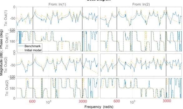
This chapter explains in details the modeling process of the beam-piezo system for centralized controller design. The governing equation is first deduced from Finite Element Modeling and then simplified and corrected to compensate the error introduced by the simplification. Based on this governing equation, a state-space model (the so-called full-order model) is deduced which contains a wider frequency band than the considered disturbance. Grey-box identification is first applied to optimize some of the parameters such that the full-order model match the benchmark. Then a multi-variable model reduction method is proposed and applied to the full-order model which gives a high quality reduced-order model. The reduced-order model is the to-be-controlled system for controller design.
Chapter 5: Centralized controller design
This chapter tackles the design process of the centralized controller. For better understanding, a brief introduction of the standard H∞ control problem with respect to performance and robust stability is fist introduced. Then it is ap-plied to solve our particular vibration problem by proposing the H∞ criterion according to specified control objectives. The proposed criterion is applied on the considered structure by properly choosing weighting functions. For the ease of implementation, the obtained H∞ controller is further reduced without los-ing closed-loop stability and degradlos-ing performance. The effectiveness of the reduced-order controller is verified by simulations and experiments. Finally, a
discussion is given to explain the limitation of a SISO controller with respect to our specific objectives.
Chapter 6: Modeling for distributed control
This chapter introduce our method for deducing a distributed model. The dis-tributed model refers to the interconnection of LTI subsystems that correctly reflects the global dynamics of the structure. For this purpose, the structure is first discretized into cells. Multiple techniques are applied to obtain the gov-erning equations of the cells. The state-space representations of subsystems are deduced from the local assembly of a small number of cells such that the neigh-bour subsystems are orthogonal. This method is validated by comparing the global responses of the distributed model with those of the model built for cen-tralized control.
Chapter 7: Conclusions and future research
This chapter summarizes this research and outlines potential directions for future research.
Chapter 2
Background
This chapter provides the background of this research. It gives an extensive literature review on active vibration control including the employment of smart materials, the common used control laws for active vibration controller design (centralized) and an overview on distributed control of flexible structures.
2.1
Smart materials for active vibration control
Smart materials are materials that are able to generate strain based on the change of external physical environment such as temperature, electric field or magnetic field, etc. This is the result of the coupling effects described by constitutive equations. According to [9], there exist several popular smart materials such as
Shape Memory Alloys (SMA), Magnetostrictive materials, Magneto-rheological (MR) and Piezoelectric materials. Here, we will give a brief introduction of these
smart materials as well as their properties which gives the choice of the type of material used in this research.
Shape Memory Alloys (SMA) are able to ‘remember’ its original shape and return
to its predeformed shape when heated. They are only sensitive at low frequencies with low precision. As a result, they are little used in active vibration control. However, we could still find some applications, for example in [37].
Magnetostrictive materials generates strain under magnetic field. They can be
used in compress situation as load carrying mechanisms [38] because it has maxi-mum response when it is subjected to compress load. TERFENOL-D is the most popular magnetostrictive material. In some applications like sonar, TERFENOL-D can be an alternative choice of PZT.
Magneto-rheological (MR) is a particular viscous fluid that contains particles of
magnetic material in micron-size. They are mainly used in semi-active vibration control of suspension systems [39].
Piezoelectric materials can be used as actuators as well as sensors because of
its bidirectional piezoelectric effect. Ceramics and Polymers are two classes of piezoelectric materials mainly used in vibration control. The piezopolymers are not usually used as actuators because of the high voltage requirement and the limited control authority. Thus, they are mostly used as sensors. The best known piezopolymer is the Polyvinylidene Fluoride (PVDF). The application of PVDF in active vibration control can be seen for example in [40,41]. The piezoceramics can be used as both actuators and sensors. They are applicable for a wide frequency band, till ultrasonic frquencies in some applications. They also have high precision up to the nanometer range1 [9]. The most popular piezoceramic is
the Lead Zirconate Titanate (PZT). PZT patches can be glued or co-fired on the target structures which makes it very applicable for light structures. Piezoelectric
materials are the most commonly used smart materials in active vibration control
[10].
Considering the properties of these smart materials, we conclude that the piezo-electric materials, especially the PZT patches, are the most suitable for active vibration of light weighted flexible structure such as an aluminum beam consid-ered in this research. It has advantages over other materials in many aspects such as mechanical simplicity, small volume and lightweight, wide working frequency band, high precision, and the ability of high level integration in the structure. As mentioned above, piezoelectric materials can be used to control the vibration because of its bidirectional piezoelectric effect which is first discovered by the Curie brothers in 1880 [42,43]. In particular, they find that squeezing particular materials leads to the change of electric charge. This phenomenon allows piezo-electric materials to be used as strain sensors. On the other hand, the converse
effect is also possible which means that it is able to generate a mechanical strain under the application of an electric voltage. This allows the use of piezoelectric materials as actuators. Active vibration control using piezoelectric materials has attracted considerable interest of the researches during the past few decades. To design efficient piezoelectric smart structures for active vibration control, both structural dynamics and control laws have to be investigated as introduced in the next section.
2.2
Active vibration control of flexible
struc-tures
As far as the researches about active vibration (centralized) control of flexible structures, various methods have been developed in the past few decades. Gen-erally, the design process for an active vibration control problem involves many steps. A typical scenario is as follows [44]:
1. Analyze the property of the to-be-controlled structure.
2. Deduce a reliable mathematical model of the to-be-controlled structure by using techniques such as Finite Element Analysis or data-based modeling method (e.g. the identification techniques).
3. Reduce the model (if necessary) such that it has less degree of freedoms and lower dimension2.
4. Analyze properties, dynamic characteristics of the resulting model. Properly define the disturbance.
5. Quantify requirements for sensors and actuators and decide their types as well as their locations on the structure.
6. Analyze the effect of the chosen actuators and sensors on the global dynamics of the structure.
7. According to the control objectives, quantify performance criterion and sta-bility trade-offs.
8. Decide the control law to be applied and design a controller to satisfy the quantified control requirements.
9. Validate the desired control requirements of the controlled system by simu-lations. If the controlled system fails to satisfy the requirements, adjust the requirements or modify the control law.
10. Choose proper hardware and the corresponding software and integrate them on an experimental benchmark.
11. Design experiments and perform system identification. Update the model if necessary.
12. Implement the obtained controller. Perform experiment and necessary mea-surements to evaluate the actual performance on the real-life system.
13. Repeat some of the above steps if the actual performance does not meet the control objectives.
In design process, depending on the circumstances, it is possible to follow dif-ferent steps from the above scenario. However in any case, a reliable simplified mathematical model is first needed. Various modeling and model reduction tech-niques could be applied. Model updating is also necessary if the model does not have enough accuracy. Then, according to the control objectives, we need to quantify the requirements, choose the type of actuators and sensors and decide their positions. At last, apply proper control law and design a controller that satisfies specified performance criterion and stability trade-offs. Simulations and experiments are necessary to validate the obtained controller.
For the modeling part, a lot of researches concerning the modeling of piezoelectric materials incorporated into flexible structure apply the Finite Element Modeling (FEM) and the System Identification [45–51]. FEM is based on the principles of mechanics and physical laws and gives partial differential equations whose parameters possess actual physical sens. However, such equations will have a large number of DOF and dimensions. There exist various model reduction methods allowing us to reduce such finite element models for example the Modal Displacement Method [27], the Krylov Subspace Method [52], the Rayleigh–Ritz method [53], etc. On the contrary, System Identification ignores the mechanics and physical laws and builds the model in the perspective of systems and control.
It performs data matching and directly obtain the transfer function (or state-space representation) that reflects the input-output behavior of the structure. There also exist methods to reduce such models as discussed in [54]. In addition, It is also possible to combine these two modeling techniques as it is concerned in this research.
For the control part, there exists a lot of control laws applied under various cir-cumstances and aimed at controlling different types of systems. For example the feedforward or feedback control employed for systems that are linear or non-linear, time-invariant or time-variant. To be specific, the smart structure studied in this research is considered as a Linear Time Invariant (LTI) system and we focus on the feedback control law for such LTI structures. In the literature on active vibration control for LTI systems, methods have first been developed to design Single Input Single Output (SISO) controllers to control one resonant mode with a collocated actuator-sensor pair. Such methods include PID control [55–57], Velocity Feedback control [9, 16, 58–60], Acceleration feedback control [13,61, 62], Positive Position Feedback (PPF) control [63–66], etc. These meth-ods have their limitations. First, as mentioned, they are only able to control one resonant mode. To control more modes, one have to design different con-trollers for each mode and combine them in parallel as discussed in [9,65]. This is indeed a solution however with low efficiency and performance. Second, these methods require collocated actuator-sensor pair which limits the applicability. Otherwise, the closed-loop stability could not be guaranteed as evidenced in [9]. Third, if too many modes are concerned, one actuator-sensor pair will no longer be sufficient. A Multi Input Multi Output (MIMO) controller using multiple actuator-sensor pairs is thus required. There indeed exists modified version of the above mentioned methods which allows us to design a MIMO controller such as a modified version of PPF [67,68]. However, it is not a systematic controller synthesis method and is not as efficient as the later developed modern control design methods. Recently, modern control design methods have been increas-ingly applied in active vibration control of flexible structures which allows us to design MIMO controllers that control multiple modes. Such methods include Pole Placement control [69], Linear Quadratic Gaussian/Regulator (LQG/LQR) [70–75], H2 control [76], H∞ control [77–82], etc. These modern control methods have the advantage over classical control methods in that they are applicable to both SISO and MIMO systems and do not require collocated actuator-sensor
pair. While H∞ control has the advantage over other modern methods in that it provides satisfactory robustness properties in the presence of parametric and dynamic uncertainties [32] which are not easy to obtain with Pole Placement, LQG/LQR or H2 control. The consideration in robustness properties allows us to avoid the spillover instability [83,84], which is the most important motivation of applying H∞ control in this research.
At last, it is important to notice that all these active vibration control methods are mainly applied to reduce the global vibration of a flexible structure with re-spect to an excitation over a relatively small frequency band (control one mode with SISO controller or control a few modes with MIMO controller). To the best of our knowledge, this research is the first one proposing a technique that allows to particularly reduce the vibration in a specific zone where there is no actuator or sensor and with respect to an excitation covering a large frequency band (con-taining as many as eleven modes). How to adapt H∞ control to such objectives is thus a big challenge which constitutes the main scientific contribution of this work.
2.3
Distributed control of flexible structures
For the active vibration control problem, the general objective will always be controlling as many modes as possible with the best performance. Such objec-tive could be achieved by giving smart structures more actuation and sensing capabilities which requires the use of more actuators and sensors. However, in the presence of a large number of actuators and sensors, designing a centralized controller will require high computational cost and high level of physical connec-tivity. An alternative way is to design distributed controllers which is referred to as the distributed control. Distributed controllers work in a different way from centralized controllers in that one controller only reacts with a local part of the structure, for example connects with a few number of actuators and sen-sors that are close to each other which forms a local control unit. Several such controllers working together to achieve a global control effect. For this purpose, the smart structure will be spatially discretized and thus can be considered as a spatially interconnected system (or spatially distributed system) [85]. Each
subsystem will have actuation and sensing capabilities which allow it to be con-nected with a distributed controller. Moreover, neighbor controllers will change information between each other which helps them to achieve global control ob-jectives. Fig. 2.1[85] shows the architecture of such spatially distributed control system where G denotes the interconnected subsystems of the smart structure and K the distributed controllers. There also exists a similar control architecture which is the so-called decentralized control [86] where different controllers do not communicate with each other. However, it has been proven on an actuated beam in [85, 87] that the distributed control can achieve better performance than the decentralized control.
Figure 2.1: Architecture of a spatially distributed control system
In order to control such spatially interconnected system, methods have been de-veloped in the recent few years to design distributed controllers. Raffaello and Geir [88] propose a state-space framework to design distributed controllers for systems with highly structured interconnection topology. Analysis and synthesis conditions are formulated in terms of Linear Matrix Inequality (LMI). Applica-tions of this framework can be found in [85,89–91]. In particular, this framework assumes that the interconnected architecture is spatially invariant. However, such architecture is typically not given in real-life applications where the archi-tecture could be spatially variant as it will be concerned in this research. Thus, extended methods are developed for spatially variant systems [92–94] or hetero-geneous systems [95–97]. To obtain the model of the spatially interconnected system, multiple techniques are available such as the Distributed identification [98, 99], the FEM [90], the combination of Distributed identification and FEM [100], etc.
2.4
Summary
This chapter gives an extensive literature review on active vibration control of smart structures. The review includes the employment of smart materials on flexible structures for the purpose of active vibration control, the modeling and control methods (centralized) as well as the typical scenario of the controller design process, and the overview of the distributed control. The focus of this review is on the centralized control.
Chapter 3
System description
This section will give a detailed introduction of the experimental setup and the control objectives. We will also explain the physical connections between the setup and the to-be-designed controller which will, in the sequel, be taken into account in the modeling part and the controller design process.
3.1
Experimental setup
The concerned system is a flexible structure with smart materials, the so-called smart structure. The used smart materials here are piezoelectric patches that will be used as sensors and actuators. The actuators generate certain efforts to counteract with the structural vibration in order to reduce it, which is considered as the active vibration control. In this dissertation, attention is focused on a particular situation where the vibration must be rejected in a specific location of the structure where smart materials cannot be placed. We thus aim at reducing the vibration in a specific zone by only using the measurements in other zones with a centralized or a distributed controller.
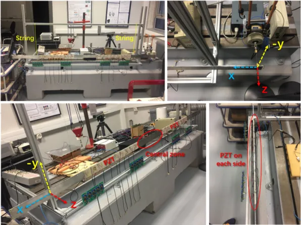
To reproduce the problem described above, the following experimental setup (beam-piezo system) is considered, see Fig. 3.1. It is made of a long thin alu-minum beam with a number of piezoelectric transducers (PZT) and under the excitation of an electrodynamical shaker at the right end.
Figure 3.1: Setup pictures: a general view (top left), the shaker (top right), central zone and PZT locations (bottom left), PZT pairs (bottom right)
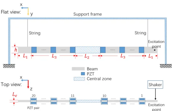
Fig.3.2is the schematic diagram of the setup on flat and top view which presents more details. The beam is hung on a solid shelf which creates a free-free boundary condition and which limits the displacement in y direction. Two times 10 pairs of PZT patches cover two zones L3 around the central zone of the beam (zone L2). These PZT are used in pairs which means that two PZT at the same location but on different sides of the beam are used together as one actuator (or sensor) in order to generate reversed force on two sides of the beam which gives a balanced control torque. For this purpose, the polarization of the two PZT as a pair must be towards the same direction as shown in Fig. 3.3 such that when a voltage is applied, the PZT on top and bottom of the beam deform in opposite directions which creates a balanced torque. There are in total 20 PZT pairs numbered from 1 to 20 (10 pairs on each side of the central zone). The excitation is a force disturbance applied by an electrodynamical shaker (top right figure in Fig. 3.1) along z-axis at the right end of the beam and the excitation point is in the middle of its height (h). This means that the disturbance will mainly excite the bending
Figure 3.2: Schematic diagram of the setup: flat view (top); top view (bottom)
of x−y plane which results in lateral displacement in z-axis. In addition, because of the high long-width ratio and the free-free boundary condition, Euler-Bernoulli assumptions [101] can be used where shear stress and rotational inertia can be neglected. This assumption will be considered in the modeling of the beam-piezo system as detailed in Chapter 4. This also corresponds to the way that the PZT pairs are pasted which makes the bending moment the most effective to be captured. The dimensions and the material parameters are listed in Table 3.1.
Figure 3.3: PZT polarization and the resulting balanced control torque under voltage load
Table 3.1: Setup dimensions and parameters
Property Value
Beam density (Aluminum), ρ 2720 kg/m3
Beam total length, L 2.5 m
Beam ends, L1 0.45 m
Beam center, L2 0.42 m
Beam middle with PZT, L3 0.59 m
Beam hight, h 0.053 m
Beam thickness, Le 0.003 m
PZT material type FerroPerm Pz26
PZT dimensions 0.05m × 0.05m × 0.0005m
Distance between PZT 0.01 m
Maximum voltage for PZT (guideline) 200 V AC/mm Cross-section area of beam, AS 159 mm2
Young’s modulus (Aluminum), Yang 69 GP a
3.2
Control objectives and considerations
The general objective is to use the smart materials as actuators and sensors to particularly reduce the vibration at a specific zone of a flexible structure by only using the measurements in other zones, which can be interpreted as to tackle unmeasured performance variables (see e.g. [102] for an example in another context). As to our experimental setup (Fig.3.1), we aim at designing a feedback controller (centralized or distributed) that allows to significantly reject the vibration energy from the central zone (the part with length L2 shown in Fig. 3.2) when the beam is subject to an external force disturbance at one end of the beam.
The disturbance is applied along z-axis and thus only the vibration in z-axis is of interest. As to the frequency band of the disturbance, if we forget the complexity of the feedback controller, the ideal goal is of course to reject a dis-turbance with a power spectrum density (PSD) which covers the largest possible frequency band, in other words, to control as many vibration modes as possible. However, the general control ability and the maximum possible performance will necessarily depend on the sensitivity of the actuator, which means that we can only effectively control the modes within the working range (sensitive range) of the actuator. In our case, the used piezoelectric material is Pz26 (see, Table3.1)
which has a very large working range. The force disturbance applied by the elec-trodynamical shaker is chosen to have high PSD in (600, 3000)1 rad/s which is
within the working range of the PZT. This bandwidth covers 11 vibration modes2
and the modes outside this bandwidth will thus not be controlled. Consequently, the disturbance is chosen to have large PSD in (600, 3000) rad/s. To the best of our knowledge, this dissertation is the first one proposing a technique that aims to significantly reduce a vibration covering a frequency band with as many as 11 modes in a specific zone free of actuating and sensing transducers.
As to the controller design, the challenging objective of controlling such many modes requires the use of modern multi-variable control design methods. The first reason for this is that modern control design methods allow us to tackle unmeasured performance variables such as the vibration in the central zone where there is no sensor. Second, as it will be discussed in Section 3.3, in order to successfully control the 11 modes in (600, 3000) rad/s, at least two sensors and two actuators are necessary for a centralized controller. We thus have to design a multi-variable (MIMO) controller. As for distributed control, all the 20 PZT pairs should be used which requires even more complex control design methods. Some other considerations must also be taken into account. First, in order to guarantee the designed control effect on the actual setup, an accurate model is of crucial importance, especially for active vibration control. There are ways to build the theoretical model knowing the values of the physical parameters and geometry of the materials (i.e. Table 3.1). However, there are always errors and it will be further illustrated in Section 4.1.6 that the theoretical model is far from being accurate enough. Therefore, model correction is necessary, for example, using the identification technique which corrects the model using the measurement data from the actual setup and yields an updated model which will have much better accuracy. Second, to ensure a good feasibility of the implementation, the order of the controller should be relatively low, which implies that a low-order model containing only the modes in (600, 3000) rad/s should be used to compute the controller because, as we will see in the sequel, the identified model will have to contain modes outside the frequency band of interest (called the full-order model in the sequel). This introduces a robust stability requirement that the low-order model based controller must also guarantee the
1About (95, 477) Hz
stability when applied on the full-order model. This is also to avoid the so-called spill-over problem3. Third, the controller should have reasonably high magnitude
in (600, 3000) rad/s to ensure a high vibration reduction rate while relatively low magnitude outside (600, 3000) rad/s to limit energy consumption. For the same reason, we should also take care that sensor/measurement noise (usually located at high frequencies) has limited effect on the control output.
3.3
Centralized controller implementation
The designed controller will be a centralized controller (a model-based feedback controller) which collects together all the measurements (sensing voltage) from the PZT pairs used as sensors and then computes control signals (actuation volt-age) for all the PZT pairs used as actuators. Thus, the more PZT pairs we use, the more complex the controller will be, which increases computational burden and energy consumption of the control board. Thus, we need a minimum number of PZT pairs to obtain a maximum accessible performance. Considering the large bandwidth of the disturbance (i.e. (600, 3000) rad/s), we show in Appendix A
that we need at least two sensors and two actuators (a SISO controller is there-fore not sufficient). In Appendix A, we also show that an appropriate choice for these two actuators and these two sensors is to select the 10thand 16thPZT pairs
as actuators, the 5th and 11th PZT pairs as sensors (see Fig. 3.4 for the location of these PZT pairs).
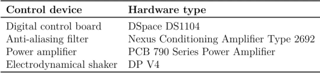
The type of all the control devices are listed in Table 3.2 and their functions are detailed as follows. The designed controller will be implemented in a pro-grammable digital control board which should be able to simulate the input-output behavior of transfer functions. Like all the other digital signal processors, this control board is equipped with ADC/DAC card in each input/output chan-nel for sampling/constructing the actual input/output signal. However, it is not equipped with internal anti-aliasing filters. Therefore, extra anti-aliasing filters are necessarily used to sample the outputs of the PZT sensors and the filtered voltage signals are collected by the control board through its own ADC cards. The force disturbance is applied by an electrodynamical shaker which needs an
3Instability problem due to the effect of actuation to the unmodeled dynamics of the
Figure 3.4: Actuators and sensors in the application
input signal as a reference to characterize the bandwidth and the magnitude of the output force. As to the actuation, the DAC cards of the control board do not have enough output power and thus power amplifiers are used to take con-trol signals from the concon-trol board and then send power to the actuators. In general, the control system can be illustrated by Fig. 3.5 where f represents the disturbance force applied by the shaker and where the (digital) control board takes as input the sensor voltages Vsof the 5th and the 11th PZT pairs (that have
been sampled after passing through anti-aliasing filters) and delivers as output the voltages Va to be applied at the 10th and the 16th PZT pairs (through power
amplifiers). These (amplified) voltages Va on the PZT actuators will induce a
force whose effect is to counteract the structural vibration (especially) in the central zone.
Table 3.2: List of the control devices
Control device Hardware type
Digital control board DSpace DS1104
Anti-aliasing filter Nexus Conditioning Amplifier Type 2692 Power amplifier PCB 790 Series Power Amplifier
Figure 3.5: Block diagram of the controlled system
3.4
Methodology overview for centralized
con-troller design
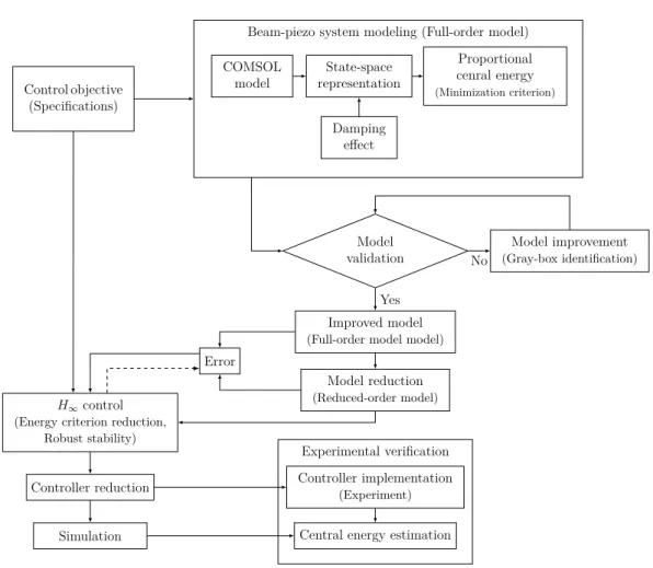
In order to design a centralized controller that achieve the control objectives described in Section 3.2 with a performance well guaranteed when applied on the actual setup, we propose the following methodology (based on H∞ control and all other modern control design techniques).
Fig. 3.6 gives a general overview of this methodology and each step will be detailed in the following chapters. First, the theoretical model of the beam-piezo system is derived using the commercial software COMSOL which performs Finite Element Analysis and modal decomposition to a virtual 3D beam model. Only a finite number of vibration modes (chosen by the user) can be tackled. This results in a state-space model that is only valid up to a certain frequency band (corresponds to the user-chosen maximum vibration mode) which is here chosen slightly larger than the maximal frequency of the disturbance i.e. 3000
rad/s. In this state-space model, the output vector is not only made up of the
voltages at the PZT pairs selected as sensors, but also of the (vibration) velocities at a number of locations in the central zone. An expression for the vibration energy in the central zone can indeed be derived from these velocities. Then, the model parameters, for which COMSOL gives a rough initial estimate, are tuned using grey-box identification in order to obtain a model with better accuracy4,
yielding the so-called full-order model of the system. The effect of all the control devices is also considered in the identification process. This (full-order) model covers a frequency band that is larger than the frequency band of interest (i.e.
4A grey-box identification approach is here preferred over a black-box approach to keep the
Control objective (Specifications)
Beam-piezo system modeling (Full-order model) COMSOL model State-space representation Proportional cenral energy (Minimization criterion) Damping effect Model validation Model improvement (Gray-box identification) Improved model
(Full-order model model)
Model reduction
(Reduced-order model)
Error
H∞control (Energy criterion reduction,
Robust stability)
Controller reduction
Simulation
Controller implementation
(Experiment)
Central energy estimation Experimental verification
No Yes
Figure 3.6: Overall design methodology
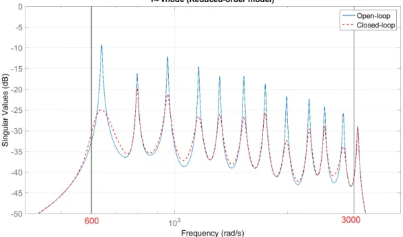
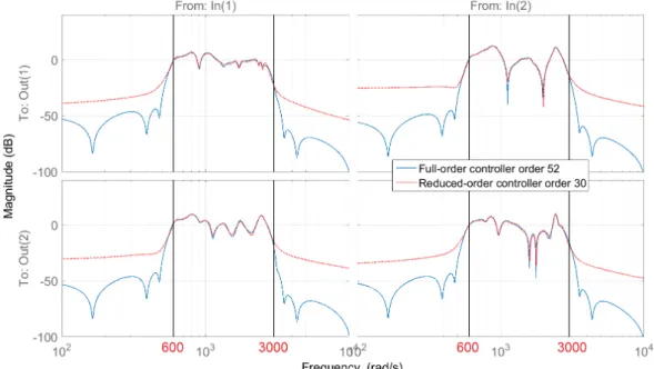
(600, 3000) rad/s). A model reduction method is therefore proposed and applied to obtain a reduced-order model that is close to the full-order model in the frequency band of interest. The reduced-order model is then used to design the controller using an H∞ control design procedure. This control design procedure aims at minimizing the vibration energy in the central zone while keeping the control efforts in acceptable proportion and ensuring that the designed controller will stabilize the full-order model. This last objective is tackled by considering the difference between the full-order model and the reduced-order model as an uncertainty. Finally, for the ease of implementation, the obtained controller is reduced without impacting the stability or degrading the performance. We validate the proposed approach by simulation and by implementing the designed controller on the real setup.
Chapter 4 will introduce the modeling of the to-be-controlled system, where we will explain how to obtain an accurate full-order model and a high quality
reduced-order model with well defined expression of the central energy. Chap-ter 5 will present how to obtain a simple centralized controller satisfying all the control objectives using H∞ control and reduction method. The simulation and experimental results are also introduced.
3.5
Overview of modeling for distributed
con-trol
For distributed control, we try to design several individual feedback controllers that locally react with the structure in order to achieve a global behavior. The desired global behavior is exactly our main objective, which is to particularly reduce the vibration in the central zone free of PZT pairs. For the implemen-tation, each controller will only connect a small number of PZT pairs that are very closely located. As a result, we will consider a section of the beam with two neighbor PZT pairs as a to-be-controlled subsystem (one actuator and one sensor) which will be connected with a distributed controller as a local feedback control unit. In this dissertation, we will introduce the modeling method which allows us to deduce the state-space model of LTI subsystems such that the struc-ture (beam with PZT pairs) can be considered as their interconnection, which will be called the distributed model. In particular, some of the subsystems will have actuation and sensing capabilities and will be connected with controllers forming a control unit. Other subsystems without actuation and sensing capa-bilities will only contribute to the global dynamics of the beam, for example the velocities of the points in the central zone which are also necessary for computing the vibration energy. Considering that the setup is a long thin beam, we will dis-cretize the beam into sections along its length and will obtain several subsystems such that one subsystem only communicates with its left and right neighbours. Moreover, there should be no algebraic relations between the states of neighbour subsystems which is very important for distributed controller synthesis.
In the modeling part, we will first spatially discretize the structure according to the position of PZT pairs into different types of cells (cells with and without PZT pairs). The governing equation of each type of cell can be deduced using COMSOL and then be simplified by keeping the least number of DOF. Using
these governing equations, we perform local assembly and then deduce the state-space model of subsystems. It is important to note that in order to avoid algebraic relations, one subsystem and one cell will not be identical. Finally, to verify this method, the distributed model (interconnection of subsystems) and the model built for centralized control (before identification) should have the same global responses. The identification of the distributed model and the controller synthesis are the future works and will not be tackled in this dissertation.
3.6
Summary
This chapter gives a detailed picture of the experimental setup. The dimension of the beam and the piezoelectric material chosen for actuating and sensing as well as all the control devices are listed. The basic operating principle of the piezoelectric patches is also explained. We consider an excitation in a large frequency band that contains 11 vibration modes. The main control objective is to use these piezoelectric patches as actuators and sensors, compute a feedback controller that reduces the vibration energy in the central part of the structure free of actuating and sensing transducers. Other considerations are also taken into account for example the energy consumption of the controller, the ability of tolerating a certain level of measurement noise, avoiding spill-over problem (guarantee the robust stability), etc. In order to effectively control all the modes in the frequency band of interest, we carefully choose two PZT pairs as actuators and another two PZT pairs as sensors which requires a MIMO controller of 2 × 2. The design process for a centralized controller is generally explained as a guide for the discussion of the following chapters. We also point out that we will finally turn to distributed control with the same objective and we will introduce in this work our method for building interconnected LTI subsystems used for distributed controller design.
Modeling for centralized control
In this chapter, we will build a state-space model of the beam-piezo system. The so-called beam-piezo system model is the model of the setup with the force disturbance f , the actuation voltage vector Va as inputs and the sensing voltage
vector Vsas output as illustrated in Fig.3.5. Additionally, we will also construct
another to-be-controlled output vector with which we can deduce an expression of the vibration energy in the central zone. Moreover, for model based controller design, we assume that the effects of the actual control devices in the control loop (i.e. the power amplifiers that provides Va, the anti-aliasing filters used to
sample Vs and the DAC/ADC card in each channel of the digital control board)
can be considered as constant gain, phase shift and time delay. As we will see in the sequel, this phase shift will also be approximated by a pure time delay. For the modeling of the beam-piezo system, we first perform Finite Element Modeling using COMSOL which gives us a global governing equation of the beam-piezo system with its parameters computed by COMSOL. The governing equation is then transformed into a state-space model (initial model). This model is actually a truncated model which ignores the dynamics at higher frequencies. To validate this model, we compare its frequency response with the response measured from the actual setup and find that this initial model is not accurate enough. Thus, model improvement using grey-box identification technique is performed to correct some of the model parameters. In this procedure, the effects of the actual control devices in the control loop are also taken into account in order to fit as much as possible the model with the actual setup. As to the controller design, the complexity of an H∞ controller will always be larger than