INTERNATIONAL ATOMIC ENERGY AGENCY VIENNA ISBN 978–92–0–130410–0
!
@
Edited by:
Mitsuru Kikuchi
Karl Lackner
Minh Quang Tran
Edited by:
Mitsuru Kikuchi
Karl Lackner
Minh Quang T
ran
It provides an introduction to nuclear fusion and its status and prospects, and features specialized chapters written by leaders in the field, presenting the main research and development concepts in fusion physics. It starts with an introduction to the case for the development of fusion as an energy source. Magnetic and inertial confinement are addressed. Dedicated chapters focus on the physics of confinement, the equilibrium and stability of tokamaks, diagnostics, heating and current drive by neutral beam and radiofrequency waves, and plasma–wall interactions. While the tokamak is a leading concept for the realization of fusion, other concepts (helical confinement and, in a broader sense, other magnetic and inertial configurations) are also addressed in the book. At over 1100 pages, this publication provides an unparalleled resource for fusion physicists and engineers.
The Agency’s Statute was approved on 23 October 1956 by the Conference on the Statute of the IAEA held at United Nations Headquarters, New York; it entered into force on 29 July 1957. The Headquarters of the Agency are situated in Vienna. Its principal objective is “to accelerate and enlarge the contribution of atomic energy to peace, health and prosperity throughout the world’’.
ALBANIA ALGERIA ANGOLA ARGENTINA ARMENIA AUSTRALIA AUSTRIA AZERBAIJAN BAHRAIN BANGLADESH BELARUS BELGIUM BELIZE BENIN BOLIVIA
BOSNIA AND HERZEGOVINA BOTSWANA BRAZIL BULGARIA BURKINA FASO BURUNDI CAMBODIA CAMEROON CANADA CENTRAL AFRICAN REPUBLIC CHAD CHILE CHINA COLOMBIA CONGO COSTA RICA CÔTE D’IVOIRE CROATIA CUBA CYPRUS CZECH REPUBLIC DEMOCRATIC REPUBLIC OF THE CONGO DENMARK DOMINICA DOMINICAN REPUBLIC ECUADOR EGYPT EL SALVADOR ERITREA ESTONIA ETHIOPIA FINLAND FRANCE GABON GEORGIA GERMANY GREECE GUATEMALA HAITI HOLY SEE HONDURAS HUNGARY ICELAND INDIA INDONESIA
IRAN, ISLAMIC REPUBLIC OF IRAQ IRELAND ISRAEL ITALY JAMAICA JAPAN JORDAN KAZAKHSTAN KENYA KOREA, REPUBLIC OF KUWAIT KYRGYZSTAN
LAO PEOPLE’S DEMOCRATIC REPUBLIC LATVIA LEBANON LESOTHO LIBERIA LIBYA LIECHTENSTEIN LITHUANIA LUXEMBOURG MADAGASCAR MALAWI MALAYSIA MALI MALTA MARSHALL ISLANDS MAURITANIA MAURITIUS MEXICO MONACO MONGOLIA MONTENEGRO MOROCCO MOZAMBIQUE MYANMAR NAMIBIA NEPAL NETHERLANDS NEW ZEALAND NICARAGUA NIGER NORWAY OMAN PAKISTAN PALAU PANAMA
PAPUA NEW GUINEA PARAGUAY PERU PHILIPPINES POLAND PORTUGAL QATAR REPUBLIC OF MOLDOVA ROMANIA RUSSIAN FEDERATION RWANDA SAUDI ARABIA SENEGAL SERBIA SEYCHELLES SIERRA LEONE SINGAPORE SLOVAKIA SLOVENIA SOUTH AFRICA SPAIN SRI LANKA SUDAN SWEDEN SWITZERLAND SYRIAN ARAB REPUBLIC TAJIKISTAN
THAILAND
THE FORMER YUGOSLAV REPUBLIC OF MACEDONIA TUNISIA
TURKEY UGANDA UKRAINE
UNITED ARAB EMIRATES UNITED KINGDOM OF
GREAT BRITAIN AND NORTHERN IRELAND UNITED REPUBLIC
OF TANZANIA
UNITED STATES OF AMERICA URUGUAY UZBEKISTAN VENEZUELA VIETNAM YEMEN ZAMBIA ZIMBABWE
EDITED BY:
MITSURU KIKUCHI
KARL LACKNER
MINH QUANG TRAN
INTERNATIONAL ATOMIC ENERGY AGENCY VIENNA, 2012
© IAEA, 2012 Printed by the IAEA in Austria
September 2012 STI/PUB/1562
IAEA Library Cataloguing in Publication Data
Fusion physics. — Vienna : International Atomic Energy Agency, 2012. p. ; 24 cm.
STI/PUB/1562
ISBN 978–92–0–130410–0 Includes bibliographical references.
1. Nuclear fusion. 2. International Thermonuclear Experimental Reactor (Project). 3. Controlled fusion — International cooperation. 4. Tokamaks — International cooperation. I. International Atomic Energy Agency.
IAEAL 12–00774
All IAEA scientific and technical publications are protected by the terms of the Universal Copyright Convention as adopted in 1952 (Berne) and as revised in 1972 (Paris). The copyright has since been extended by the World Intellectual Property Organization (Geneva) to include electronic and virtual intellectual property. Permission to use whole or parts of texts contained in IAEA publications in printed or electronic form must be obtained and is usually subject to royalty agreements. Proposals for non-commercial reproductions and translations are welcomed and considered on a case-by-case basis. Enquiries should be addressed to the IAEA Publishing Section at:
Marketing and Sales Unit, Publishing Section International Atomic Energy Agency
Vienna International Centre PO Box 100 1400 Vienna, Austria fax: +43 1 2600 29302 tel.: +43 1 2600 22417 email: [email protected] http://www.iaea.org/books
Recreating the energy production process of the Sun — nuclear fusion — on Earth in a controlled fashion is one of the greatest challenges of this century. If achieved at affordable costs, energy supply security would be greatly enhanced and environmental degradation from fossil fuels greatly diminished. Fusion Physics describes the last fifty years or so of physics and research in innovative technologies to achieve controlled thermonuclear fusion for energy production.
The International Atomic Energy Agency (IAEA) has been involved since its establishment in 1957 in fusion research. It has been the driving force behind the biennial conferences on Plasma Physics and Controlled Thermonuclear Fusion, today known as the Fusion Energy Conference. Hosted by several Member States, this biennial conference provides a global forum for exchange of the latest achievements in fusion research against the backdrop of the requirements for a net energy producing fusion device and, eventually, a fusion power plant. The scientific and technological knowledge compiled during this series of conferences, as well as by the IAEA Nuclear Fusion journal, is immense and will surely continue to grow in the future. It has led to the establishment of the International Thermonuclear Experimental Reactor (ITER), which represents the biggest experiment in energy production ever envisaged by humankind.
The IAEA also would like to thank the editors of the book, M. Kikuchi, K. Lackner and Minh Quang Tran, for preparing this comprehensive manuscript on fusion, including magnetic and inertial fusion concepts. They have selected a prominent group of contributors, many of whom have provided seminal scientific contributions to important developments in the field. The IAEA also conveys its gratitude to the authors for their long standing cooperation. Their work is highly appreciated, and this present compendium will help to raise awareness of the opportunities offered by fusion and the path towards a demonstration fusion power plant.
In 1958, during the second Conference on Peaceful Uses of Nuclear Energy in Geneva, nuclear fusion research was declassified. At this time the basis of nuclear fusion science and technology was confined to a few books and monographs written by ‘pioneers’.
After this event, the tradition to periodically exchange the latest discoveries in fusion research development was established by the International Atomic Energy Agency (IAEA) through its series of Fusion Energy Conferences (IAEA FECs). It was natural that in 2008 the 22nd IAEA FEC came back to the same location in Geneva, the Palais des Nations, to celebrate the fiftieth anniversary of the declassification.
The progress over the past half century has been immense. We are now in the building phase of the International Thermonuclear Experimental Reactor (ITER) with the prospect of having 500 MW of fusion power in the second half of the 2020s and starting studies for the step beyond ITER, a demonstration reactor (usually referred to as the DEMO power plant). A new generation of scientists and engineers is needed to build and exploit ITER and accompanying fusion devices, and to prepare the next step beyond ITER. Master and PhD programmes have been set up in many universities worldwide to train what is usually referred to as the “ITER Generation of Scientists”. Compared to 1958, the growth of the field of nuclear fusion has led to a multiplicity of specialized subfields, each having its own textbooks.
The occasion of the 2008 IAEA FEC prompted us to propose to the IAEA International Fusion Research Council (IFRC) to sponsor a tutorial book for post-graduate students. Our aim is to provide an introduction to nuclear fusion, its status and perspectives. Specialized chapters are devoted to the main concepts under R&D (magnetic and inertial conferment) together with the physics as well as the technology basis. With the strong support and under the guidance of the IFRC, we have invited international experts to contribute to the project. Our vision of the book was shared by all contacted colleagues, who enthusiastically accepted this difficult tutorial task.
It is our hope that the material presented will allow post-graduate level students to become familiar with the topics of their studies. More advanced researchers will also find materials on topics adjacent to their field of specialization. The progress in nuclear fusion research is such that it has become impossible to cover in detail all the key issues: this book is not intended to replace specialized monographs or review articles.
The book starts with an introduction to the case for the development of fusion as an energy source, followed by chapters on the physics of confinement, equilibrium and stability of tokamaks. Diagnostics, heating and current drive by neutral beams and radiofrequency waves, and plasma–wall interactions
(helical confinement concepts and, in a broader sense, other magnetic configu-rations) have also received wide interest worldwide. Last but not least, inertial confinement fusion is one of the important lines of research, which naturally finds its place in the book. The later part of the book is oriented towards ITER and fusion technology.
The realization of this book would not have been possible without the enthusiastic commitment of all authors, who took upon themselves the task of sharing their vast knowledge with the ITER generation in parallel with their research duties. We would like to wholeheartedly thank them for their dedication. Our responsibility has also included careful reading of the contributed manuscripts. That was done with the help of a few colleagues, whose contribution is gratefully acknowledged.
Last but not least, our appreciation also goes to the IAEA and its staff, which provided an unfailing support and encouragement. We would like to particularly thank G. Mank, R. Kamendje, R. Kaiser and T. Desai, whose support throughout this endeavour has rendered the publication of this volume possible. We also would like to acknowledge the very useful contribution of B. Gulejova, whose professional expertise has helped solve a multitude of editorial issues.
Mitsuru Kikuchi Karl Lackner Minh Quang Tran
Although great care has been taken to maintain the accuracy of information contained in this publication, neither the IAEA nor its Member States assume any responsibility for consequences which may arise from its use.
The mention of names of specific companies or products (whether or not indicated as registered) does not imply any intention to infringe proprietary rights, nor should it be construed as an endorsement or recommendation on the part of the IAEA.
The authors are responsible for having obtained the necessary permission for the IAEA to reproduce, translate or use material from sources already protected by copyrights.
Material prepared by authors who are in contractual relation with governments is copyrighted by the IAEA, as publisher, only to the extent permitted by the appropriate national regulations.
This publication has been prepared from the original material as submitted by the authors. The views expressed do not necessarily reflect those of the IAEA, the governments of the nominating Member States or the nominating organizations.
The IAEA has no responsibility for the persistence or accuracy of URLs for external or third party Internet web sites referred to in this book and does not guarantee that any content on such web sites is, or will remain, accurate or appropriate.
CHAPTER 1
THE CASE FOR FUSION
1.1. INTRODUCTION ... 1 1.2. ENERGY SCENARIOS ... 3 1.2.1. Near term energy scenario ... 5 1.2.2. Long term energy scenario and the role of fusion ... 7 1.3. FUSION BASICS ... 14 1.3.1. What is fusion? ... 14 1.3.2. Fusion power gain Q ... 17 1.3.3. Fusion reactions ... 20 1.3.4. Fusion fuels ... 23 1.3.5. Direct conversion to electricity... 26 1.4. APPROACHES TO FUSION ... 26 1.4.1. Magnetic confinement fusion ... 27 1.4.1.1. Progress in tokamak based magnetic confinement fusion research... 32 1.4.2. Inertial confinement fusion ... 35 1.4.2.1. Progress in inertial confinement fusion research ... 38 1.5. SOCIOECONOMIC PERSPECTIVES ... 40 1.5.1. Environment, safety and non-proliferation ... 40 1.5.1.1. Emissions in normal operation ... 40 1.5.1.2. Possible accidents ... 41 1.5.1.3. Waste ... 41 1.5.2. Cost comparison with other sources of energy ... 42 1.5.2.1. Direct costs of fusion power production ... 42 1.5.2.2. External costs of fusion power production ... 45 1.5.3. Public acceptance of fusion ... 46 1.5.4. Spin-offs of fusion research ... 47 1.6. CONCLUSION ... 51
CHAPTER 2
PHYSICS OF CONFINEMENT
2.1. INTRODUCTION AND OVERVIEW ... 59 2.2. NEOCLASSICAL TRANSPORT ... 63 2.2.1. Introduction ... 632.2.4. The drift kinetic equation ... 71 2.2.5. Bootstrap current ... 75 2.2.6. Magnetic field ripple ... 78 2.2.7. Transport in a stochastic field ... 82 2.3. TURBULENT TRANSPORT ... 83 2.3.1. Introduction ... 83 2.3.2. Examples of basic microinstabilities ... 86 2.3.2.1. Electron drift instabilities ... 86 2.3.2.2. Ion temperature gradient instabilities ... 89 2.3.3. Non-linear gyrokinetic equations for tokamak turbulence ... 91 2.3.4. Kinetic description of microinstabilities ... 95 2.3.4.1. Linear onset condition for ion temperature gradient mode .. 96 2.3.4.2. Electron temperature gradient instability ... 99 2.3.4.3. Trapped particle instabilities ... 99 2.3.5. Spatial structure of microturbulence... 103 2.3.5.1. Role of magnetic shear: Sheared slab geometry ... 104 2.3.5.2. Role of toroidal geometry: Ballooning representation ... 106 2.3.5.3. Role of zonal flow shear ... 108 2.3.6. Different channels of turbulence transport ... 110 2.3.6.1. Ion thermal transport ... 111 2.3.6.2. Electron thermal transport ... 113 2.3.6.3. Particle transport ... 114 2.3.6.4. Momentum transport ... 116 2.3.7. Physics of transport barriers ... 118 2.4. GLOBAL ENERGY CONFINEMENT SCALING STUDIES ... 123 2.4.1. Introduction ... 123 2.4.2. Energy confinement scalings: Dimensional parameters ... 124 2.4.2.1. Ohmic and L-mode plasma confinement trends ... 124 2.4.2.2. H-mode confinement trends and scalings ... 128 2.4.2.3. Advanced statistical methods and error analysis ... 133 2.4.3. Dimensionless analysis ... 136 2.4.3.1. Basics ... 136 2.4.3.2. Scalings ... 139 2.4.4. L-H threshold scalings ... 140 2.4.5. Implications relative to theoretical models ... 144 2.5. LOCAL TRANSPORT ... 145 2.5.1. Basics ... 145 2.5.2. Models ... 147 2.5.2.1. Neutral beam models ... 147
2.5.2.4. Current drive models ... 152 2.5.3. Perturbative transport ... 155 2.5.4. Profile stiffness ... 160 2.5.5. Transport barriers ... 163 2.5.5.1. Core ... 163 2.5.5.2. Edge ... 169 2.5.6. Comparison with theoretical models ... 173 2.6. TuRbulENCE MEasuREMENTs ... 176 2.6.1. Measurement techniques... 177 2.6.1.1. Probe techniques ... 177 2.6.1.2. Electromagnetic wave scattering ... 178 2.6.1.3. Electromagnetic wave reflectometry ... 179 2.6.1.4. Electromagnetic wave Doppler backscattering (Dbs) ... 180 2.6.1.5. Phase contrast imaging (PCI) ... 181 2.6.1.6. Heavy ion beam probe (HIbP) ... 181 2.6.1.7. beam emission spectroscopy (bEs) ... 182 2.6.1.8. High frequency charge exchange spectroscopy (HF CHERs) ... 183 2.6.1.9. Correlated electron cyclotron emission (CECE) ... 183 2.6.1.10. analysis techniques ... 184 2.6.2. Experimental results ... 185 2.6.2.1. Wavenumber spectra ... 185 2.6.2.2. Frequency spectra ... 187 2.6.2.3. Radial profiles ... 189 2.6.3.3. Ion and electron temperature fluctuations ... 191 2.6.3.4. Zonal flows and geodesic acoustic modes ... 192 2.6.3.5. Core turbulence suppression ... 194 2.6.3.6. Evidence for non-local effects ... 195
CHAPTER 3
EQUILIBRIUM AND MACROSCOPIC STABILITY
OF TOKAMAKS
3.1. INTRODuCTION ... 225 3.1.1. basic tokamak configuration ... 227 3.1.2. Timescales of tokamak dynamics ... 228 3.2. TOKaMaK EQuIlIbRIuM ... 230 3.2.1. The straight cylinder ... 231 3.2.2. Toroidal plasma equilibrium ... 232 3.2.2.1. The large aspect ratio approximation ... 234the plasma equilibrium ... 239 3.2.2.4. Shaping of plasma cross-section and the tokamak poloidal field system ... 242 3.2.2.5. Axisymmetric stability of tokamak equilibria ... 244 3.3. THEORY OF MACROSCOPIC INSTABILITIES IN TOKAMAKS ... 246 3.3.1. One-fluid MHD stability theory ... 246 3.3.1.1. Ideal MHD stability ... 246 3.3.1.2. Effects of dissipation on linear stability of global modes ... 269 3.3.1.3. Finite amplitude perturbations ... 281 3.3.2. Extensions to the MHD model ... 287 3.3.2.1. Introduction ... 287 3.3.2.2. Derivation example: reduced (low frequency) MHD ... 291 3.3.2.3. Derivation example: two-fluid equations ... 296 3.3.2.4. Relation to kinetic models ... 299 3.3.2.5. Qualitative two-fluid effects on MHD instabilities ... 300 3.3.3. Energetic particle physics and kinetic MHD ... 302 3.3.3.1. Introduction ... 302 3.3.3.2. Models ... 303 3.3.3.3. Global modes in toroidal geometry... 306 3.4. ExPERIMENTAL OBSERVATIONS OF MHD MODES ... 316 3.4.1. Internal kink modes ... 317 3.4.2. Classical tearing modes ... 322 3.4.3. Neoclassical tearing modes (NTMs) ... 325 3.4.4. Edge localized modes (ELMs)... 327 3.4.5. Ideal pressure limiting modes ... 331 3.4.6. Wall effects on MHD modes ... 334 3.4.7. Alfvén and energetic particle modes (EPMs) ... 337 3.5. DISRUPTIVE INSTABILITIES ... 342 3.5.1. Introduction ... 342 3.5.2. Classification by causes ... 343 3.5.2.1. Density limit disruptions ... 343 3.5.2.2. Beta limit ... 344 3.5.2.3. Limit on q ... 344 3.5.3. Phases of disruptions ... 345 3.5.3.1. Thermal quench ... 345 3.5.3.2. Current quench ... 347 3.5.4. Damage potential ... 349 3.5.4.1. Heat pulse ... 349 3.5.4.2. Electromagnetic forces ... 350
CHAPTER 4
PLASMA DIAGNOSTICS
4.1. INTRODUCTION ... 360 4.2. PASSIVE DIAGNOSTIC METHODS ... 362 4.2.1. Magnetic measurements ... 362 4.2.2. Electrical probes (Langmuir probes) ... 368 4.2.2.1. Introduction to electrical probes ... 368 4.2.2.2. Langmuir probes ... 368 4.2.3. Visible and UV spectroscopy ... 375 4.2.4. Bolometry ... 378 4.2.4.1. Thermal devices ... 378 4.2.4.2. AxUV detectors ... 382 4.2.5. Methods based on electron cyclotron emission measurements ... 384 4.2.6. Passive neutral particle analysis ... 393 4.2.7. Methods based on x ray radiation ... 400 4.2.7.1. Soft x ray radiation ... 400 4.2.7.2. High resolution x ray spectroscopy... 404 4.2.8. Experimental nuclear physics methods ... 412 4.2.8.1. Neutrons, charged fusion products, hard x rays ... 412 4.2.8.2. Gamma ray spectrometry ... 421 4.3. ACTIVE DIAGNOSTIC METHODS ... 426 4.3.1. Probing by laser beams ... 426 4.3.1.1. Thomson scattering ... 426 4.3.1.2. Laser induced fluorescence technique ... 432 4.3.2. Probing by particles ... 435 4.3.2.1. Diagnostic neutral beams for plasma studies in magnetic fusion devices ... 435 4.3.2.2. Active charge exchange recombination spectroscopy diagnostic ... 438 4.3.2.3. Motional Stark effect ... 443 4.3.2.4. Active charge exchange and Rutherford scattering ... 445 4.3.2.5. Heavy ion beam probe diagnostics ... 449 4.3.3. Probing by microwaves and laser beam: interferometry, polarimetry, reflectometry ... 452 4.3.3.1. Introduction ... 452 4.3.3.2. Interferometry and polarimetry ... 454 4.3.3.3. Plasma reflectometry for electron concentration profile measurements ... 4734.4. ENGINEERING PROBLEMS ... 485 4.4.1. Changing of mechanical properties ... 486 4.4.2. Changing in electrical properties... 486 4.4.3. Changes in optical properties ... 487 4.5. CONCLUSION ... 489
CHAPTER 5
PLASMA HEATING AND CURRENT DRIVE BY NEUTRAL
BEAM AND αLPHA PARTICLES
5.1. HEATING AND CURRENT DRIVE PHYSICS BY NEUTRAL BEAM AND ALPHA PARTICLES ... 535 5.1.1. Basic processes of neutral beam injection ... 535 5.1.2. Physics of ionization of injected neutral beam ... 537 5.1.3. Multi-step ionization and Lorenz ionization ... 540 5.1.4. Energy transfer to electrons and ions by neutral beam injection ... 543 5.1.5. Energetic particle orbits on the axisymmetric magnetic surfaces ... 546 5.1.6. Fast ion behaviour and high temperature production with NB injection 549 5.1.7. Physics of neutral beam current drive: fast ion distribution function ... 551 5.1.7.1. Rayleigh–Ritz method ... 553 5.1.8. Physics of neutral beam current drive: shielding current and NBCD efficiency ... 554 5.1.9. Experimental observation of beam-driven current ... 558 5.1.10. Physics of ripple loss of fast ions: banana drift and ripple trapped losses ... 560 5.1.11. Physics of particle trajectories in non-axisymmetric fields ... 563 5.1.12. Alpha heating ... 565 5.1.13. D-T experiments in large tokamaks (TFTR and JET) ... 568 5.2. NEUTRAL BEAM HEATING ... 571 5.2.1. Introduction ... 571 5.2.2. Ion source... 575 5.2.2.1. Plasma generator ... 575 5.2.2.2. Multicusp source ... 576 5.2.2.3. Radiofrequency plasma source ... 578 5.2.3. Extraction and acceleration ... 579 5.2.3.1. Child–Langmuir Law ... 579 5.2.3.2. Multi-stage acceleration ... 581 5.2.3.3. Beamlet steering ... 582 5.2.4. Positive-ion-based NBI ... 5845.2.5.2. Advantages of volume production ... 590 5.2.5.3. Caesium seeding ... 592 5.2.6. Negative ion extraction/acceleration ... 594 5.2.7. Negative-ion-based NBI ... 595 5.2.7.1. N-NBI for JT-60 ... 595 5.2.7.2. N-NBI for LHD ... 596 5.2.7.3. N-NBI for ITER... 597 5.2.8. MV power supply ... 599 5.2.9. Remarks on future NBI technology ... 600
CHAPTER 6
RADIOFREQUENCY WAVES, HEATING AND CURRENT
DRIVE IN MAGNETICALLY CONFINED PLASMAS
6.1. INTRODUCTION ... 609 6.2. THEORY OF RF WAVE PROPAGATION IN A MAGNETIZED PLASMA ... 611 6.2.1. Electron cyclotron waves ... 620 6.2.2. Lower hybrid wave propagation and accessibility... 624 6.2.3. Ion cyclotron wave propagation and accessibility ... 630 6.2.4. ICRF wave absorption in a hot plasma ... 633 6.2.4.1. Absorption on electrons ... 634 6.2.4.2. Absorption of ICRF waves on ion cyclotron harmonics ... 635 6.2.4.3. Minority ion cyclotron absorption ... 637 6.2.5. Quasi-linear absorption of ICRF waves on ions ... 638 6.2.6. Quasi-linear absorption on electrons ... 642 6.2.6.1. Lower hybrid current drive ... 642 6.2.6.2. Electron cyclotron current drive ... 645 6.2.6.3. Current drive by the fast ICRF waves ... 647 6.2.7. Wave propagation in toroidal geometry, geometric optics ... 648 6.2.7.1. Geometric optics and the ray equations ... 649 6.2.7.2. Modifications to wave accessibility and absorption in toroidal geometry ... 651 6.2.7.3. Numerical simulations of lower hybrid current drive using coupled Fokker–Planck and ray tracing calculations .. 652 6.2.8. Wave propagation in toroidal geometry, full-wave treatment ... 653 6.2.8.1. Full-wave simulations of minority heating in the ICRF ... 653 6.2.8.2. Full-wave simulations of mode conversion in the ICRF ... 656 6.2.8.3. Full-wave simulations of lower hybrid waves ... 6576.3.1. ICRF heating and current drive experiments ... 659 6.3.2. ICRF antenna and transmission line design ... 666 6.3.2.1. ICRF transmission line architecture ... 666 6.3.2.2. ICRF source technology... 667 6.3.2.3. ICRF transmission line design ... 669 6.3.2.4. ICRF wave launchers ... 671 6.3.3. Lower hybrid heating and current drive experiments ... 677 6.3.4. Lower hybrid wave launchers ... 682 6.3.4.1. RF coupling theory... 685 6.3.4.2. Numerical coupling codes ... 687 6.3.4.3. Evolution of LH launchers in tokamaks ... 690 6.3.5. Applications of electron cyclotron heating and current drive... 694 6.3.5.1. Wave propagation and absorption experiments ... 695 6.3.5.2. Electron cyclotron current drive (ECCD) experiments ... 703 6.3.6. Electron cyclotron transmission line and antenna design ... 710 6.4. GYROTRONS FOR ECR HEATING AND CURRENT DRIVE ... 714 6.4.1. Introduction to gyrotrons ... 714 6.4.2. Physical principles of the gyrotron ... 716 6.4.3. Overview of gyrotron theory... 717 6.4.4. Engineering features of the gyrotron ... 722 6.4.4.1. Electron gun and beam tunnel... 722 6.4.4.2. Gyrotron cavity ... 723 6.4.4.3. Internal mode converter (IMC) ... 723 6.4.4.4. Phase correcting mirrors and output window ... 724 6.4.4.5. Depressed collector ... 724 6.4.4.6. Auxiliary components ... 726 6.4.5. State of the art gyrotrons ... 726 6.4.6. Prospects and future directions ... 730 6.4.6.1. Multi-megawatt gyrotrons ... 730 6.4.6.2. Frequency tuneable gyrotrons ... 731 6.4.6.3. Improvement of gyrotron efficiency ... 732 6.4.6.4. Gyrotrons for DEMO... 732
CHAPTER 7
PLASMA–WALL INTERACTIONS
7.1. INTRODUCTION ... 756 7.2. BASIC PHYSICAL PROCESSES AND UNDERLYING THEORY ... 758 7.2.1. Basic concepts... 7587.2.1.3. The scrape-off layer ... 762 7.2.2. Recycling ... 764 7.2.3. Atomic and molecular processes ... 767 7.2.4. Erosion processes ... 772 7.2.4.1. Physical sputtering ... 772 7.2.4.2. Chemical sputtering ... 774 7.2.4.3. Arcing ... 777 7.3. DEVELOPMENT OF PLASMA FACING MATERIALS ... 779 7.3.1. Carbon containing materials ... 779 7.3.2. Beryllium ... 782 7.3.3. High-Z materials ... 784 7.3.4. Mixed materials ... 784 7.4. PRESENT PROGRESS OF PLASMA–WALL INTERACTIONS IN TOKAMAKS ... 786 7.4.1. Wall conditioning ... 786 7.4.1.1. Surface cleaning ... 787 7.4.1.2. Plasma assisted coating of thin films ... 789 7.4.2. Impurities and dusts ... 791 7.4.2.1. Impurities ... 791 7.4.2.2. Dusts ... 793 7.4.3. Erosion and re-deposition ... 794 7.4.3.1. Divertor erosion and re-deposition ... 794 7.4.3.2. Limiter erosion and re-deposition ... 795 7.4.3.3. Main chamber wall erosion and re-deposition ... 795 7.4.4. Hydogen isotope retention and removal ... 796 7.5. CONTROL OF PLASMA–WALL INTERACTIONS ... 798 7.5.1. Divertors ... 798 7.5.1.1. Introduction ... 798 7.5.1.2. Divertor operation regimes ... 799 7.5.1.3. Effect of divertor geometry ... 806 7.5.2. Particle transport in the divertor SOL ... 810 7.5.2.1. Plasma flow and drift effects ... 810 7.5.2.2. Recent advances on cross-field particle transport ... 819 7.5.3. Energy deposition ... 823 7.5.3.1. Steady state power load on the divertor ... 823 7.5.3.2. Transient energy deposition during ELMs ... 827 7.5.3.3. Active control of peak heat fluxes ... 831
7.6.1. Power handling and particle exhaust ... 832 7.6.2. Transient heat loads ... 833 7.6.3. Material migration... 835 7.6.4. Control of in-vessel tritium inventory ... 835 7.6.5. Integrated PWI issues for steady state operation ... 836
CHAPTER 8
HELICAL CONFINEMENT CONCEPTS
8.1. INTRODUCTION ... 847 8.2. HELICAL CONFINEMENT CONCEPTS ... 849 8.2.1. Production of 3-D toroidal flux surfaces... 849 8.2.2. Helical confinement devices ... 852 8.2.2.1. Classical stellarators ... 853 8.2.2.2. Torsatrons/Heliotrons ... 855 8.2.2.3. Heliacs ... 858 8.2.2.4. Modular stellarators ... 859 8.3. THE PHYSICS OF HELICAL SYSTEMS ... 861 8.3.1. Heating and particle–wave interaction ... 861 8.3.1.1. Electron cyclotron heating and current drive ... 861 8.3.1.2. Electron Bernstein wave heating in stellarators ... 866 8.3.1.3. Ion cyclotron heating in helical systems ... 868 8.3.2. Plasma equilibrium ... 870 8.3.2.1. Basic equilibrium properties ... 870 8.3.2.2. Optimized stellarators ... 871 8.3.2.3. Computation of 3-D equilibria ... 873 8.3.2.4. Experimental equilibrium identification ... 874 8.3.3. Plasma stability ... 877 8.3.3.1. Introduction and theoretical background ... 877 8.3.3.2. Ballooning modes ... 881 8.3.3.3. Global pressure driven modes ... 882 8.3.3.4. Energetic particle driven Alfvén instabilities ... 885 8.3.4. Bounce-averaged particle orbits ... 894 8.3.5. Neoclassical transport models ... 896 8.3.5.1. Neoclassical modelling ... 896 8.3.5.2. Classical and advanced stellarator configurations ... 898 8.3.5.3. Radial electric field ... 899 8.3.5.4. Bootstrap current ... 900 8.3.5.5. Parallel resistivity ... 9008.3.6.1. Role of neoclassical transport ... 904 8.3.6.2. Characterization of turbulent transport ... 906 8.3.6.3. Particle transport ... 909 8.3.6.4. Electron temperature evolution... 911 8.3.6.5. Isotopic effect ... 912 8.3.6.6. Magnetic configuration effects on confinement ... 913 8.3.6.7. Improved confinement regimes ... 915 8.3.6.8. Impurity transport ... 918 8.3.7. Boundary layer and divertor physics ... 923 8.3.7.1. Island divertor concepts ... 923 8.3.7.2. Transport features of helical SOLs ... 924 8.3.7.3. Detachment regime ... 928 8.4. OPERATIONAL LIMITS ... 930 8.4.1. Density limit ... 930 8.4.2. Beta limit ... 933 8.5. STELLARATOR OPTIMIZATION ... 936 8.5.1. Equilibrium ... 936 8.5.2. Particle drift ... 936 8.5.3. Stability ... 938 8.5.4. Integrated optimization concepts ... 938 8.6. HELICAL REACTOR CONCEPTS ... 941 8.6.1. Heliotron reactors ... 941 8.6.2. Modular stellarator reactors ... 942 8.6.2.1. US compact stellarator power plant study (SPPS) ... 943 8.6.2.2. The Helias reactor ... 944 8.6.3. Concluding remarks ... 945
CHAPTER 9
THE BROADER SPECTRUM OF MAGNETIC
CONFIGURATIONS FOR FUSION
9.1. INTRODUCTION ... 958 9.2. REVERSED FIELD PINCH: TOROIDAL CONFINEMENT AT WEAK MAGNETIC FIELD ... 959 9.2.1. The configuration: ideal MHD equilibrium and stability ... 961 9.2.1.1. Current driven instability ... 964 9.2.1.2. Pressure driven instability... 964 9.2.2. Reversal of magnetic field: minimum energy state and reconnection .... 965 9.2.2.1. Minimum energy state ... 9659.2.3. Confinement: effects of magnetic stochasticity ... 972 9.2.4. Improved confinement ... 976 9.2.4.1. Eliminating the free energy source ... 976 9.2.4.2. Single helicity states ... 979 9.2.5. Beta limits in the RFP ... 982 9.2.6. Resistive wall instabilities and their control ... 984 9.2.6.1. Characteristics of resistive wall instabilities in the RFP ... 984 9.2.6.2. Feedback suppression of resistive wall instabilities ... 985 9.2.7. Sustaining the plasma ... 986 9.3. COMPACT TORI: ELIMINATING THE HOLE IN THE TORUS ... 990 9.3.1. Spheromaks ... 990 9.3.1.1. Magnetic surfaces ... 990 9.3.1.2. Spheromak formation ... 991 9.3.1.3. Sustainment phase and helicity injection ... 994 9.3.1.4. Current amplification ... 997 9.3.1.5. Regular versus stochastic magnetic field ... 998 9.3.1.6. Spheromak: a flexible configuration ... 998 9.3.2. Field reversed configuration (FRC) ... 1000 9.3.2.1. Field geometry ... 1000 9.3.2.2. FRC formation ... 1002 9.3.2.3. FRC equilibrium ... 1003 9.3.2.4. Plasma rotation and stability ... 1005 9.3.2.5. Steady state FRCs... 1006 9.4. OPEN CONFINEMENT SYSTEMS ... 1008 9.4.1. Confining a plasma on the open field lines ... 1008 9.4.2. Mirror confinement ... 1008 9.4.3. Role of ion collisions ... 1010 9.4.4. Electron axial confinement ... 1011 9.4.5. Velocity-space microinstabilities... 1012 9.4.6. MHD stability ... 1014 9.4.7. Suppression of end losses ... 1015 9.4.7.1. Tandem mirrors ... 1015 9.4.7.2. Plasma rotation ... 1018 9.4.7.3. Gas-dynamic trap ... 1019 9.5. OTHER FUSION CONFIGURATIONS: A BROAD RANGE OF IDEAS ... 1020 9.5.1. Levitated dipoles ... 1020 9.5.2. Cusps ... 1022 9.5.3. Magneto-electrostatic confinement and electrostatic confinement ... 1023
9.5.6. Other concepts ... 1025 9.6. SUMMARY ... 1026
CHAPTER 10
INERTIAL FUSION ENERGY
10.1. BRIEF HISTORY ... 1043 10.2. INTRODUCTION ... 1044 10.3. BASIC CONCEPT OF INERTIAL FUSION ENERGY ... 1044 10.4. REQUIREMENT ON FUSION GAIN ... 1046 10.5. IMPLOSION CONCEPT ... 1048 10.5.1. Why compression? ... 1048 10.5.2. Gain scaling of implosion ignition ... 1050 10.6. IMPLOSION PHYSICS ... 1051 10.6.1. Ablative acceleration and laser–throughout plasma interaction in direct drive implosion ... 1053 10.6.2. Classical absorption ... 1054 10.6.3. Collective laser plasma interactions ... 1055 10.6.3.1. Resonant mode conversion ... 1056 10.6.3.2. Density profile modifications ... 1058 10.6.3.3. Electron–ion decay and oscillating two stream instabilities 1058 10.6.3.4. Two-plasmon decay instability ... 1059 10.6.3.5. Stimulated Raman scattering... 1060 10.6.3.6. Stimulated Brillouin scattering ... 1061 10.6.3.7. Filamentation instability: self-focusing ... 1062 10.7. ABLATION PRESSURE AND DIRECT DRIVE IMPLOSION HYDRODYNAMICS ... 1063 10.7.1. Ablation pressure... 1063 10.7.2. Rocket model and hydrodynamic efficiency ... 1065 10.7.3. Implosion non-uniformity and stability ... 1065 10.7.4. Implosion instabilities ... 1068 10.8. FAST IGNITION: PRESENT STATUS AND FUTURE PROSPECTS ... 1069 10.8.1. Why fast ignition? ... 1069 10.8.2. Ignition conditions ... 1070 10.8.3. Fast ignition integrated experiments ... 1074 10.8.3.1. Direct plasma heating ... 1074 10.8.3.2. Cone-shell target ... 1076
10.8.4.2. Radiation hydrodynamic simulation ... 1078 10.8.5. Relativistic electron generation, transport and heating physics ... 1080 10.8.6. Petawatt laser and future Fast Ignition Facility ... 1082 10.9. INDIRECT DRIVE FUSION ... 1085 10.9.1. Concept of indirect drive implosion ... 1085 10.9.2. Status of indirect drive implosion experiments ... 1088 10.9.3. Recent progress in indirect drive experiments... 1090 10.9.4. Other drivers for indirect drive implosion ... 1093 10.10. IFE POWER PLANT DEVELOPMENT ... 1095 10.10.1. IFE power plant systems ... 1095 10.10.2. Driver development ... 1097 10.10.3. Reaction chamber ... 1099 10.10.4. Fuel pellet ... 1101 10.10.5. Recent progress in inertial fusion technologies ... 1102 10.10.5.1. LIFE project at LLNL ... 1102 10.10.5.2. HiPER project in the EU ... 1103 10.10.5.3. Recent progress in laser technology ... 1104 10.10.5.4. Recent progress of target fabrication and injection technology... 1105
INDEX
... 1119THE CASE FOR FUSION
P.K. Kaw, I. Bandyopadhyay Institute for Plasma Research, Bhat, Gandhinagar, Gujarat, India 1.1. INTRODUCTION
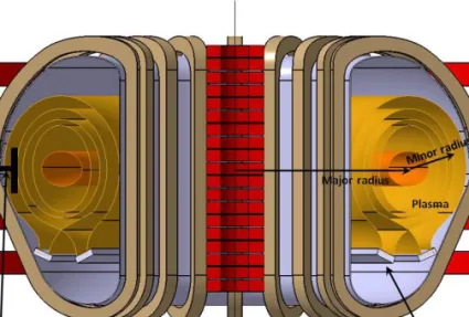
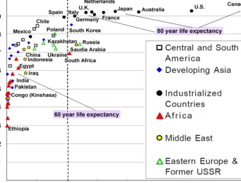
Humans do not live by bread alone. Physically we are puny creatures with limited prowess, but with unlimited dreams. We see a mountain and want to move it to carve out a path for ourselves. We see a river and want to tame it so that it irrigates our fields. We see a star and want to fly to its planets to secure a future for our progeny. For all this, we need a genie who will do our bidding at a flip of our fingers. Energy is such a genie. Modern humans need energy and lots of it to live a life of comfort. In fact, the quality of life in different regions of the world can be directly correlated with the per capita use of energy [1.1–1.5]. In this regard, the human development index (HDI) of various countries based on various reports by the United Nations Development Programme (UNDP) [1.6] (Fig. 1.1), which is a parameter measuring the quality of life in a given part of the world, is directly determined by the amount of per capita electricity consumption. Most of the developing world (~5 billion people) is crawling up the UN curve of HDI versus per capita electricity consumption, from abysmally low values of today towards the average of the whole world and eventually towards the average of the developed world. This translates into a massive energy hunger for the globe as a whole. It has been estimated that by the year 2050, the global electricity demand will go up by a factor of up to 3 in a high growth scenario [1.7–1.9]. The requirements beyond 2050 go up even higher.
How is humankind going to produce the vast amount of energy it needs? In the absence of any new developments, the workhorse is likely to be based on fossil fuels. On the other hand, the use of fossil fuels as the major source of energy over the last century has led to significant global warming through the emission of greenhouse gases. Also, the fossil fuel reserves have started depleting with only coal, the largest emitter of CO2, having the potential to last a few hundred years. Oil and gas reserves have already started dwindling and would last a few tens of years by various estimates; political and military conflicts for control of oil and gas have already dominated the world energy scenario over the last decade. Deployment of conventional fission based nuclear power, on the other hand, has faced serious public opposition due to concerns of proliferation, radioactive hazardous wastes, the potential for catastrophic Chernobyl like disasters, etc., all
politically and technically soluble problems and yet a matter of concern even today. Alternative clean energy resources such as solar and wind, though having the potential to become a major source of energy, yet have to significantly address issues of energy density (which makes them unsuitable for large urban industrial complexes), efficiency and cost of production before they can become a viable alternative. Thus the human race is at a critical juncture today, when we need to quickly develop a viable alternative source of clean energy with easy global accessibility which can lead to sustainable development.
FIG. 1.1. United Nations human development index as a function of per capita energy use in kWh (60 countries, 1997). Electricity consumption increases with human development. Courtesy of Ref. [1.1].
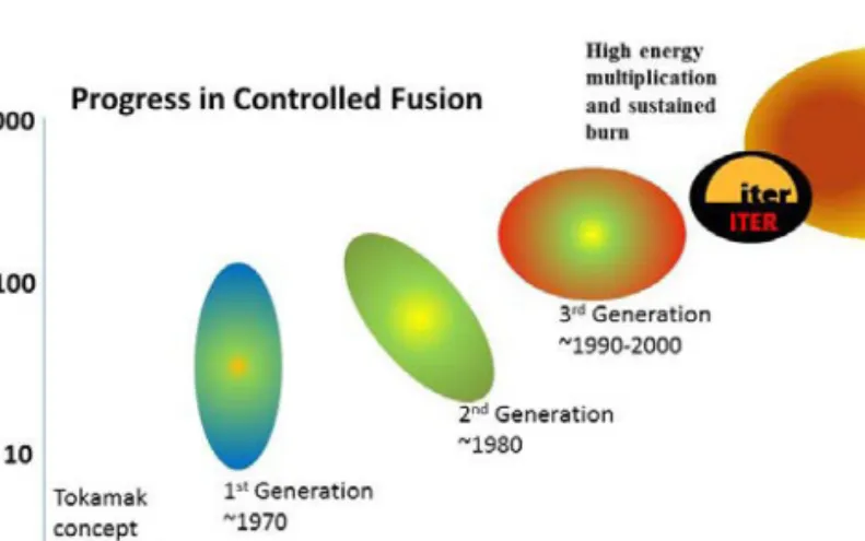
It takes considerable time to develop new energy technologies and even more time for them to be established as an alternate energy source in a cost effective, safe and environmentally friendly way. Thus it is not too early to start now. In this chapter we shall present a case for rapid development and deployment of energy produced by nuclear fusion, an advanced nuclear technology with none of the concerns of proliferation or accident scenarios of conventional fission reactors and minimal radioactive wastes. Nuclear fusion research has seen a remarkable progress since it started in a major way about 50 years ago and it has culminated in the start of construction of the first experimental fusion reactor called ITER [1.10] in a wonderful cooperation involving in effect more than
half of the world’s humanity. This is particularly gratifying because finally the world is coming to realize that global problems have to be solved by burying national differences and working together to find technical solutions to difficult problems. The world of today is a highly interconnected web where the engine of industrial growth in one region is fuelled by investments from another region and the economic ills and stagnation of one region directly influence the prosperity in another region. Hence this cooperation in nuclear fusion research may become a model for the technical solution of other global problems in the future.
In Section 1.2 we give a brief description of the energy needs of the developing and the developed world to bring out with clarity the magnitudes of energy requirements in the near term (say up to the year 2050) and in the longer term (for the rest of the century), the methods which are likely to be employed in the absence of any new technologies, the consequences for our environment and how we might benefit in the long term by the use of non-fossil fuel sources of energy. We also argue that for fulfilling the demand of centralized industrial and urban centres, it will be necessary to promote the growth of CO2 free nuclear energy sources to about 40% of the total demand. Among advanced nuclear technologies, a special place is filled by nuclear fusion because of its merits such as easy, universal and almost unlimited access to the basic fuel, reduced and more benign wastes, better safety features and the promise suggested by recent technical developments in the field. Many of these features are detailed in the subsequent sections. Thus in Section 1.3 we discuss the basic fusion process itself, including the merits of fusion, the fusion reactions likely to be exploited and the possibility of using advanced fuels. In Section 1.4 the basic approaches to fusion have been summarized, with the bulk of the discussion on magnetic confinement and the tokamak concept. A discussion is also provided for the inertial fusion energy concept and the two large experiments, namely the US based National Ignition Facility (NIF) [1.11] and the Laser Mega Joule (LMJ) [1.12] experiment of France. In Section 1.5 we discuss the various socioeconomic issues of relevance to the public acceptability of fusion, such as the costs, safety issues and spin-offs, and in the final section we conclude our discussion.
1.2. ENERGY SCENARIOS
The main energy resource for the world in the past few centuries has been fossil fuels. Analysis carried out by the World Energy Council (WEC) [1.13], the International Energy Agency (IEA) [1.14] and other international organizations in 1996 estimated that the fossil fuel resource lives based on reserves of coal, natural gas and petroleum (using present technologies) were 231, 63 and 44 years respectively [1.15]. Furthermore, the resource lives based on total resource base including non-conventional oil resources such as oil shale, tar sand and heavy oil, or gas resources such as shale gas from the Devonian period, tar sand gas,
underground aquifers, coal bed methane, methane hydrate and deep layer gas (using evolving technologies) may be a few hundred years. Thus if we so desire, fossil fuel resources may last us a hundred years or so. However, it is worth noting that the fossil fuel wealth which has been created by millions of years of geological evolution on the Earth, and which may be needed for sundry reasons (other than burning) by our grandchildren and their progeny, will have been squandered away in about 300 years of modern human civilization.
Furthermore, the massive use of fossil fuels for energy production during the past century has started seriously degrading our environment. Greenhouse gases are causing a significant warming of the planet with all the associated consequences. Massive use of coal has also made phenomena like smog and acid rain a common predicament of our major urban centres. If we increase the consumption of fossil fuels by a factor of three, the consequences for the global environment are likely to be staggering. In view of the above discussion, it is unlikely that the use of fossil fuels for energy production will have an unfettered growth in spite of the needs.
On the other hand, present day fission based nuclear energy, although it plays an important supportive role (or even dominant role in countries such as France), has associated safety, radioactive waste disposal and proliferation issues. Similarly, power plants based on renewable resources such as wind or solar, while already growing at a significant pace, will continue to play only a supportive role because of the low energy density and lack of suitability to power urban industrial complexes.
Thus, although we may be able to somehow satisfy our energy needs in the short term, what is the remedy for long term energy needs and who is going to take up the challenge? Fortunately, of late there is a growing recognition among governments around the world of the possible disastrous consequences of uncontrolled global warming [1.16] and the need for supporting the development of new energy technologies. Many governments have set a target of not allowing a temperature rise of more than 2oC. This would need reduction of carbon emissions by about 80% over the next half a century [1.17]. It is important to note that there are starkly contrasting requirements on the energy chain, with the ever increasing global demand on the one hand and the environmental and social concerns on the other. Furthermore, energy systems leading to sustainable development of the entire human race must address the needs of the present without compromising those of future generations. Hence we must look for alternative energy resources which neither stress the ecosystem beyond the present level, nor totally exhaust the already dwindling fuel reserves to prevent future generations from their use for various applications. The new energy resources must be developed well in time, taking into account the following:
y
y They must be based on efficient and clean energy conversion processes with widespread public acceptance and involvement.
y
y They must lead to sustainable development of the entire world, so must be based on virtually inexhaustible resources, available globally without having to depend on resources from politically unstable regions.
y
y They must be sufficiently energy dense, capable of driving large scale industries, without requiring very large scale, widely distributed installations. 1.2.1. Near term energy scenario
In the near term, specifically over the next 20–30 years, several of the already available non-fossil energy sources which are continuously being improved for better efficiency, wider availability and reduced pollution are likely to be increasingly used to supplement the fossil fuel energy sources so as to fulfil the global energy demand as well as possibly address environmental concerns. Two such sources immediately come to mind. One is solar energy and the other is nuclear energy.
Solar energy is renewable and is hence an obvious candidate for sustainable development. Solar energy may be utilized through solar photovoltaic methods (solar cells) or through solar thermal methods (hot water for residential purposes, commercial use or electricity production) or through biofuel cultivation. In all these cases, the basic problem is the low flux of solar energy on the Earth’s surface, which makes it difficult to plan massive energy hungry industrialized urban centres running on solar energy. Nevertheless, solar energy technologies have seen remarkable development of late with the advent of nanotechnology. New plastic materials made of specially designed nanoparticles of polymer called quantum dots can convert the invisible infrared spectrum of the solar energy into electric energy. Conventional solar panels, including plastic solar cells, use the visible part of the energy, whereas about 50% of the Sun’s energy actually lies in the infrared spectrum [1.18]. Scientists from Spectrolab, a subsidiary of Boeing, have recently reported [1.19] development of multijunction solar cells with an efficiency of more than 40%, a new world record for solar photovoltaic cells. This greatly surpasses today’s industry average of 12–18% efficiencies and the best available solar cells with 22% efficiency. The Spectrolab scientists also predict that concentrator solar cells could achieve efficiencies of more than 45% or even 50% in the future, with theoretical efficiencies being about 58% in cells with more than three junctions.
Even though the early use of solar photovoltaic methods was mostly ranging from small individual appliances such as calculators to powering remote homes not connected to grids, of late a number of medium sized solar photovoltaic power plants have been installed, mainly in Europe and the USA. For example, Spain has several power stations producing tens of megawatts, the largest being the 60 MW (85 GW·h) Parque Fotovoltaico Olmedilla de Alarcón, while the 14 MW (30 GW·h) Nellice Airforce base photovoltaic station is the largest in the
USA [1.20]. Several large photovoltaic power stations are also being constructed, the largest being the 550 MW Topaz Solar Farm in California. Japan, one of the largest markets of solar energy, intends to increase its residential electric energy consumption from solar to 50% by 2030 from the present level of a fraction of one per cent [1.21]. In the USA, the goal is to meet 10% of US peak generation capacity by 2030, which would be the energy equivalent of about 180 million barrels of oil at that time [1.22].
Thus, while solar photovoltaic is gradually establishing itself as an alternative energy source, it is likely to play only a supportive role for several generations. It still has to address several issues: it lacks the energy density of other conventional large power plants, for example nuclear reactors, and so cannot be deployed in large urban industrial complexes (it needs large scale deployment). The stability of a grid with significant photovoltaic contribution, especially in winter without enough sunlight, or during night time, has not been fully studied. The high investment cost and maintainability are still issues to be resolved, as are the problems with generation of toxic wastes in the manufacturing of photovoltaic panels and their ultimate disposal.
Biofuel technologies such as the production of ethanol or biodiesel either from sugar or starch rich vegetation or from biological wastes on the other hand have also experienced significant development over the years. Biofuels are being used routinely in many countries now, mixed with conventional fuels such as petrol or diesel to be used as primary automobile fuels. Newer generation biofuels such as algae oils or oilgae [1.23], conversion of vegetable oils or biodiesel into gasoline or genetically engineered plants consuming more carbon than is released from combustion of the biofuels they produce are also becoming significant. While biofuels are likely to play a supportive role in primary fuels, they have been plagued with issues such as altering food prices as crop cultivation is reoriented from food to fuel production, or adding significantly to greenhouse emission, soil erosion, deforestation and desertification. In some developing countries the use of biofuels has contributed to arid lands, expansion of deserts, general losses of biodiversity and instability in food prices. Hence it is highly unlikely that biofuels will become a dominant primary energy source for electricity production.
The nuclear energy option based on nuclear fission, on the other hand, is a valuable one which is already being exploited at ~25% average level in the developed world. Countries such as France are even using a much higher (~78%) percentage of nuclear energy. Naturally fissile materials such as 235U will perhaps get exhausted in a few hundred years, but as one masters the use of fissile materials such as 239Pu and 233U, which can be bred from fissile materials like 238U and 232Th, fission can supply the world with energy for several thousand years. Even though nuclear energy plants can readily fulfil the needs of centralized industrial centres, wider exploitation has been curtailed because of fears of nuclear proliferation and lack of safety. This has prevented free access to nuclear
technologies. Furthermore, there are worries about the need for great care in the handling of nuclear waste. Most of these problems have technical solutions but may have significant economic and other political and social implications. Thus it is uncertain as to how much of the energy needs can be satisfied by utilization of nuclear fission power.
Thus over the next 20–30 years, the world energy scenario is likely to remain more or less the same with fossil fuels remaining the workhorse, but oil and gas gradually becoming more scarce and expensive. Conventional nuclear reactors will increase their share of energy sources, especially in emerging economies such as India, while alternative sources like solar photovoltaic and biofuels are expected to play a more significant supportive role, especially in developed economies. However, new energy technologies take significant time to establish and hence the seeds of alternative energy sources to serve the world in the long term for sustainable development need to be sown now.
1.2.2. Long term energy scenario and the role of fusion
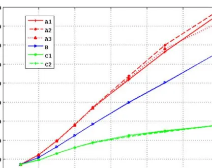
There have been several detailed attempts at developing scenarios for electricity demand and supply on both a regional as well as a global basis. Some of the most recent comprehensive ones are the studies being carried out [1.24–1.29] by the International Institute for Applied Systems Analysis (IIASA) [1.30] under the auspices of the World Energy Council (WEC) [1.13] and also the studies by the Intergovernmental Panel on Climate Change (IPCC) [1.31]. The main objective of these studies has been to estimate the upper range of future electricity supply to be assured by the existing power generating capacities along with an estimate of additional power supply capacities generated by prospective technologies. Another objective of these studies has been to determine a region-wise breakup of the possible development paths of power generation systems, especially in a scenario of fast depleting fossil fuel reserves. They also include estimates of the respective share in total installed capacities and maximum electricity supply of each technology or fuel type, including advanced energy technologies, such as thermonuclear fusion.
However, one of the problems with such studies is that they all naturally have to assume a set of likely prevailing scenarios with underlying assumptions, for example regarding population, economic and industrial growth, new technology developments, the availability of primary energy resources and a host of other factors. As a result, the predictions from these models differ somewhat depending on the underlying factors in a given scenario. For example, the IIASA– WEC study [1.32] on eleven different world regions describes three alternative cases of future economic development and energy consumption trends that further divide into six different scenarios, and quantifies their implications. Figure 1.2 shows the projected world energy consumption until the year 2100. Case “A”
corresponds to a scenario of remarkable technological improvements leading to rapid economic growth and consequently resulting in the highest energy demand. Case “B” corresponds to a more realistic and less spectacular growth scenario where technology improvements are also moderate, and consequently results in lower energy consumption. Case “C” is driven by ecological considerations for the future, though it allows for significant technological progress, especially in areas related to alternative (non-fossil) energy resources, and relies on extensive international cooperation focused on environmental protection and equitable economic growth. Consequently, the projected energy consumption in case “C” is the lowest among all scenarios.
FIG. 1.2. World Final Energy Consumption until the year 2100 in the IIASA–WEC Study “Global Energy Perspectives”. Plotted using the data from Ref. [1.32].
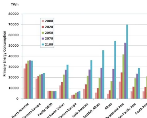
On the other hand, Fig. 1.3 shows past usage and projections from the IIASA–WEC analysis [1.30] of the total primary energy consumption in different regions of the world. Thus we see, as is well documented in many recent studies, that while the technologically advanced OECD nations show a steady saturation or small growth over this century (or even a slight decrease in North America in the later part of this century), the developing nations in South and Central Asia, such as India and China, or the Middle East nations, show a spectacular growth (up to tenfold) in primary energy consumption. In fact, it is expected that by the end of the century final energy consumption in these developing countries will be more than three times higher than in the industrialized OECD and Former Soviet
Union countries. This projection is very real, as is evident from the economies of India and China, which are already showing sustained, close to double digit, growth rates and have the potential to grow even faster throughout the coming few decades. Such sustained growth in the developing world is going to put an enormous demand on primary energy resources, which, simply stated, cannot be sustained by the ever dwindling and potentially environment degrading reserves of fossil fuels.
FIG. 1.3. Region-wise primary energy consumption in IIASA–WEC scenario B. Plotted using the data from Ref. [1.32].
In spite of differences in the predictions on the global energy scenario, there is one factor generally common to all of them: they all envisage a gradual shift away from fossil fuel sources by the end of the 21st century. Figure 1.4 shows the past actual use of various energy resources and the projections till the end of this century by the IIASA–WEC scenario B model [1.30]. Important to note in this projection is the substantially growing dependence on non-fossil-fuel resources, for example nuclear and renewables, in the second half of this century, simultaneous with gradual reduction in the dependence on oil and gas. It is important to note that, in this model, the contribution of coal remains more or less constant at the present day value.
FIG. 1.4. Evolution of primary energy shares, historical development from 1850 to 1990 and projections till 2100, for Case B. Plotted using the data from Ref. [1.32].
However, on the other hand, even though coal will be available in the world for slightly over 150 years, the prospect of countries such as India and China being forced to rely on coal for their energy demand would be disastrous to the environment of the whole Earth, as is clear from the recent discussions on the mounting evidence of an incipient global warming. The world is already experiencing a steady rise in temperature (Fig. 1.5) [1.33] and its effects are already showing in global climate changes caused by changes in flow patterns in global ocean currents, as well as depleting ice layers in the polar and Himalayan regions. Even though, as some argue, there may be uncertainties in long time predictions of climate, it would be foolhardy to assume that the uncertainties would necessarily lead to a favourable situation.
FIG. 1.5. Global average temperature over the last one and a half centuries showing a more or less steady increase over the last fifty years or so. The fluctuations and their cycles can be correlated with various events such as solar cycles [1.33].
However, as we look at nuclear energy as an important primary energy resource, it is important, in view of the uncertainties involved in a very wide acceptance of the utilization of fission power, that we do not put all our nuclear eggs in one basket. We must also look at all advanced nuclear energy technologies. Fusion is one such option. Thus, if one aims at restricting CO2 emission levels to within 450 parts per million (ppm) (the pre-industrial level being about 280 ppm), as the constraint tightens, the use of coal diminishes and the contribution from other sources increases, with fission and fusion power together playing a dominant role (see Fig. 1.6).
FIG. 1.6. Projections for CO2 emission constrained energy scenarios in Western Europe in 2100 with a large role of nuclear fusion [1.34]. (1 exajoule-electric (EJe) ~ 277.7 terawatt-hours (TW·h).)
Let us now consider for example the specific case of India. From 1981 to 2000, its GDP has grown at an average rate of 6% and since 2000, because of opening up of the economy through policy decisions, at a faster rate of close to 8%. It has the potential to grow at about 5% even as far as 2050. The ratio of its growth of electricity generation to GDP growth over the past decades has been a steady factor of about 1.2. The total electricity generated in 2002 was about 638 TW·h, of which about 66.7% was through coal and lignite, 19.6% through oil and gas and only about 3% through nuclear. Projections by the Department of Atomic Energy [1.35] predict the electricity production to go up to about 8000 TW·h by 2050, still 47% of which is likely to be resourced from coal. This scenario is very challenging and barely sustainable as this would mean the total carbon emission in India would jump from a level of about 300 metric tonnes of carbon (MtC) today to about 2100 MtC by 2050 (which is about 30% of the global carbon emissions in 2000). By a much more conservative estimate using the ANSWER/MARKAL model [1.36], the total electricity production in India
will increase to about 3000 TW·h by 2050 and about 4300 TW·h by 2100 (which still implies a carbon emission from India by 2100 of about a quarter of the global emission level). A scenario in which the global atmospheric CO2 concentration is restricted to be within 550 ppm is shown in Fig. 1.7. By this model, the restricted emission scenario can be achieved if fusion starts playing a dominant role beyond 2060 with a share of about 10% by the turn of this century, with about 430 TW·h of fusion electricity produced in India from about 67 GW of installed capacity.
FIG. 1.7. Projections of dependence on different primary energy resources in India with global CO2 emission restricted to 550 ppm by the year 2100, with India contributing only 7.5% of the global emissions. Reprinted from Ref. [1.36]. Copyright (2010), with permission from Elsevier.
These models show that fusion power is likely to give us a wonderful opportunity to provide a viable and credible solution to the long term sustainable energy needs of the world. It has none of the CO2 emission problems of fossil fuels. The amount of CO2 emission in the entire life cycle of fusion reactors (through manufacturing processes of some reactor components), as shown in Fig. 1.8 [1.37], can be up to a factor of 45 times less than that of coal based reactors of the same capacity. It is somewhat more than the CO2 emission from a comparable fission based nuclear reactor. Thus fusion power, in a way similar to fission power, can alleviate the already deteriorating climatic conditions and prospects of global warming that the world is facing today. In contrast to the renewables, it is energy dense and can therefore be used for satisfying the needs of urban industrial complexes. On the other hand, compared to the conventional fission based nuclear power plants, it has the prospect of considerably reduced long lived radioactive emission problems and inherent operational safety. The biological hazard potential of fission plants (defined in terms of the ratio of the amount of radioactive material in a reactor to the allowed level of concentration in the atmosphere) is several orders of magnitude higher than that predicted for fusion reactors. Some of the common radioactive waste materials in fission reactors, such as 131I, 90Sr or 137Cs, are highly toxic and hazardous, especially
the latter two, which have half-lives of about 30 years, which is long enough to require their absolute containment for hundreds of years. On the other hand, the main radioactive fuel in a fusion reactor, tritium, can easily be discharged from our bodies through metabolism. It is a weak (18.6 keV maximum energy) beta emitter whose radiation can easily be absorbed by a thin sheet of paper [1.37]. As a result, the allowable concentration level of tritium in the atmosphere is 500 times higher than that for 131I. However, the main potential problems of radioactivity in fusion reactors will be from neutron activated reactor components. Fusion reactors are being designed with carefully chosen low activity materials so as to require containment of less than one hundred years after decommissioning of the reactors. Thus fusion power is likely to get much more social acceptance when it becomes commercial. Moreover, the resources are plentiful to the extent that they are virtually inexhaustible and easily accessible to the entire cross-section of the world population.
FIG. 1.8. CO2 emission level of power reactors based on various fuel resources in their entire life cycle, showing fusion reactors as the third lowest CO2 emitter after hydro and fission reactors [1.37].
It is satisfying to note therefore that the tremendous amount of research and development over the last about 50 years in the field of fusion science and technology has reached a critical stage today. Scientists from some of the world’s major nations, namely, China, the whole of the European Union, India, Japan, the Republic of Korea, the Russian Federation and the USA, which together account for more than half of the world’s population, have come together to build ITER, the first experimental thermonuclear reactor which will produce energy ten times greater than the input auxiliary heating power. Various countries have national programmes to build demonstration reactors or DEMO (for example in the EU [1.38, 1.39], Japan [1.40], the USA [1.41] and India [1.42]) — some as early as
in 2030, but most likely by 2050 — which will actually supply electricity to the grid.1
In conclusion then, in the short term of the next 30–40 years, the world energy scenario is likely to be still dominated by gradually depleting fossil fuels, with nuclear fission and renewables taking a gradually increasing share. During this time fusion energy will establish itself through experiments like ITER and demonstration power plants like DEMO. In the long term, towards the end of this century, however, fusion power is likely to become commercial and play an increasingly dominant role in the world energy scenario.
1.3. FUSION BASICS 1.3.1. What is fusion?
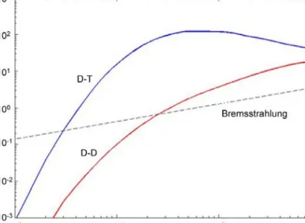
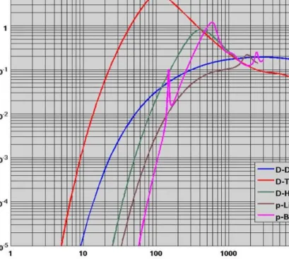
The brightest example of fusion around us is provided by the stars and the Sun, which have been burning brilliantly for billions of years using this option. In contrast to nuclear fission, where heavy nuclei like uranium are fragmented and release energy, in fusion one starts with light elements and brings them together so that they may fuse to form heavier elements. The resulting heavier elements have slightly less mass than the fusing elements and this mass difference results in the release of energy. As an example, when deuterium and tritium nuclei (which are the two heavier isotopes of hydrogen with mass numbers 2 and 3 respectively) are brought together, they fuse and form a helium nucleus and a neutron; the mass difference is released as 17.6 MeV of energy. Energy comes out in the form of the kinetic energies of the product nuclei, from which it may be trapped and used for electricity production. For fusion to occur, one has to bring the protons or heavier reactant nuclei (which are positively charged and naturally repulsive) close enough to overcome the electrostatic repulsion, so that the nuclear strong force (a very short range force), which binds the nucleons together in a nucleus, helps them fuse by a quantum mechanical tunnelling process. This is possible when the nuclei are heated to very high thermonuclear temperatures, when the kinetic energy of the thermal particles is enough to help
1 However, the 14 MeV neutron fluence in ITER at about 0.5 dpa/a (displacement per atom per year) will be much less than that of DEMO (~20 dpa/a) or other future fusions reactors. Because of this, ITER will not be able to test reactor relevant first wall materials with high neutron irradiation doses. Furthermore, neutron fluxes of pressurized water fission reactors are about 100 times lower than they would be in fusion reactors, and have lower neutron energies. So fission reactors also cannot be used to fully test fusion reactor materials. To specifically address the materials issue, therefore, the International Fusion Materials Irradiation Facility (IFMIF) [1.43] is being launched in a collaboration between Japan, the EU, the Russian Federation and the USA. IFMIF will have an accelerator based D-Li neutron source with fluence of up to 20 dpa/a.
![FIG. 1.6. Projections for CO 2 emission constrained energy scenarios in Western Europe in 2100 with a large role of nuclear fusion [1.34]](https://thumb-eu.123doks.com/thumbv2/123doknet/14829838.619244/34.765.197.577.336.582/projections-emission-constrained-energy-scenarios-western-europe-nuclear.webp)