Development of methods to take account of structural
imperfection in the critical analysis of light metallic
structures.
G.G Chewe Ngapeya
1, A. Khelil
1, A. Pamies
21Université de Lorraine, IJL UMR CNRS 7198, mail : gael.chewengapeya@uni.lu 1Université de Lorraine, IJL UMR CNRS 7198, mail : abdel.khelil@univ-lorraine.fr
2SFECE (FFB), syndicat de l’échafaudage et de l’étaiement Paris, mail : alain.pamies11@orange.fr
Abstract :
When calculating a structure, the stresses can be determined by analyzing the first or second order; the choice of method is guided by the potential influence of the deformation of the structure. In general, we can see that the scaffolding and shoring structures, due to their low rigidity (stiffness compared to buildings), come in loads of critical coefficients lower than 3. Their structural defects (imperfections) generate significant second order effects and must be taken into account. The difficulty or inaccuracy remains in the definition and the inclusion of these imperfections in an appropriate way in the calculation. The present study suggests a new definition of imperfection approach and compares the result of the bending moments due to the initial deformations introduced in a structure, according to which fully implements the approach developed or known methods. The new approach is developed using the bends or the deformations of the structure to define the shape of the deformed critical which is considered as a single imperfection. This alternative method changes the approach to Eurocode 3.
Résumé :
Il a fallu des décennies et de nombreux accidents pour reconnaitre le rôle décisif que jouent les imperfections dans tous les phénomènes d’instabilité. Les imperfections géométriques sont inévitables dans la pratique, mais peu d’attention ont jusqu’ici été portée sur l’influence combinée de tels défaut initiaux sur la réponse critique des structures. Les imperfections géométriques déclenchent d’emblée un processus de flambement par divergence qui doit être considéré comme un état limite particulièrement dangereux, contre lequel il faut se prémunir avec une sécurité convenable. Ce document présente une étude comparative des diverses méthodes de prise en compte des imperfections structurelles dans le calcul des structures d’échafaudage et d’étaiement. L’ensemble des méthodes appliquées et développées sont basés sur un fond théorique, des conventions de l’Eurocode3, un sens physique et une cohérence avec les autres méthodes. Ce document permet également de montrer que les méthodes fondées sur la définition d’une imperfection unique sont plus précises et simple du point de vue de la mécanique des structures, contrairement aux méthodes courantes d’introductions de deux imperfections de l’Eurocode3 qui certes paraissent simples, mais au final sont plus complexes et moins adaptées au comportement réel de la structure. A la suite de la présentation des diverses méthodes et leur fond, la précision des méthodes basées sur l’imperfection unique est présentée à travers le résultat de l’étude de quatre structures simples et courantes.
1. Introduction
Failure of thin structures which are subjected to compression loads is mainly due to buckling. The analysis of a structure must be made on a model and assumptions that reflect the behavior of the structure with appropriate accuracy considering the limit state. When calculating a structure, the stresses can be determined by analysing the first or second order; the choice of method is guided by the potential influence of the deformation of the structure [1]. In general, we can see that the scaffolding and shoring structures, due to their low rigidity (stiffness compared to buildings), come in loads of critical coefficients lower than 3. Their structural imperfections generate significant second order effects and must be taken into account [1-3]. The difficulty or inaccuracy remains in the definition and the inclusion of these imperfections in an appropriate way in the calculation. Our investigation aims to highlight a calculation method that is both safe and economical.
Due to the fact that the imperfections of construction elements are within the normal tolerances of manufacturing lines, they are generally not visible and can’t be quantified precisely in advance. Furthermore, the application of a compressive force on a bar with imperfections creates a bending moment (said second order moment) which in turn leads to a greater lateral deformation of the bar which result in an increase of the amplitude of the compressive axial force to the lever arm [1]. These bending moments create parasitic effects which certainly limit the load capacity of the bar [4], therefore comes the need to take into account appropriately the imperfections of the elements in the calculation of the structure.
There are the following two paths in Eurocode 3 [5] which allow us to take into account the structural defects in the calculation of our structures. One is based on conventional methods of defining local imperfections and global imperfections affecting to the structure, the other is based on the definition of a local and global single imperfection whose appearance is similar to criticism of the deformed first mode structure. Eugen Chladny and Magdalena Stujberova in their article [6] [7], on the local and global single imperfection pace with the elastic buckling mode of the structure defined a tool of determining the shape to be taken by the buckling mode for adopted as initial single imperfection. The present study suggests a new definition of imperfection approach and compares the result of the bending moments due to the initial deformations introduced in a structure, according to which fully implements the approach developed or known methods. The new approach is developed using the bends or the deformations of the structure to define the shape of the deformed critical which is considered as a single imperfection. This alternative method changes the approach to Eurocode 3.
2. Different methods of taking into account the imperfections
2.1 The local imperfection amounts and overall structure (conventional or common method of EC3)
To take into account the imperfections, the Eurocode 3 conventionally defines some conditions on the global imperfection of the local frame and the bars. These imperfections are represented by a global default initial balance of the structure and a local deformation amounts in arc. In this study these imperfections will be taken into account either by means of equivalent loads [5], or by calculating the coordinates of the nodes of the affected imperfections in the structure.
The Eurocode 3 defines:
The overall initial default plumb Φ, angle between the vertical and the direction of the structure. ∅ = ∅0𝛼ℎ𝛼𝑚 with ∅0= 1/200 ; 𝛼ℎ= (2 √ℎ ⁄ ) but 2 3< 𝛼ℎ< 1 ; 𝛼𝑚= √0,5(1 + 1 𝑚) [1]
H is the height in meters of the structure; αm the reduction coefficient for the number of bars per line; M
is the number of bars in a line, including bars supporting a vertical load NEd ≥ 50% of the average value per pole in the relevant vertical plane.
The local imperfection arch bars for flexural buckling : 𝑒0
𝐿 ⁄
With the maximum belly of the bow e0, the height L of the amount, the ratio 𝑒0⁄ is conventionally 𝐿
2.2 The local and global single imperfection
For any given frame, in terms of structural mechanics, its buckling mode (ŋcr) allows us to anticipate its local
and global behavior. Indeed, the buckling mode realizes the type of deformation that may occur to the right of each node of the structure under the effect of a load. This being can be assumed, the prior existence of a structural imperfection (ŋinit) of the same nature and oriented in the same direction that future movements
(buckling mode) up the structure in the most adverse conditions (i.e. the one will cause the reduction of the most important critical load) [8]. For the consideration of imperfections, it is planned to define a shape of global and local single imperfection which look smaller to the deformed most representative critical instability, it should give this a form amplitude will be also representative of the desired level of imperfection. The determination of this magnitude can be made assuming three (3) methods:
2.2.1 The alternative method of Eurocode 3
This method is based on the determination of a unique form of imperfection (ŋinit) which locally allows the
superposition of two elements that are: distorted criticism of the amount of the structure that houses the critical section and a deformed bar Reference whose geometrical characteristics and the critical load are the same as those of the most requested amount of the structure.
The method consists in a first approach to define conventionally the reference bar, then in a second approach, taking into account curvature point of the structure (to the right of the critical section), the curvature of the deformed criticism should be equal to the maximum curvature of the reference bar. The factor for amplifying the maximum curvature of the critical deformed so as to make locally identical to that of the reference bar is noted Cnor. It is one that will allow us to define unique distorted the whole structure. In the end, the only imperfection is, for each node of the structure, the product of the amplification factor by the end deformation of buckling mode (ŋcr) to the considered node. The normalization factor is given by:
ŋ𝑖𝑛𝑖𝑡
ŋ𝑐𝑟 = 𝐶𝑛𝑜𝑟 =
𝑒"(𝑐𝑜𝑢𝑟𝑏𝑢𝑟𝑒 𝑚𝑎𝑥 𝑏𝑎𝑟𝑟𝑒 𝑑𝑒 𝑟𝑒𝑓𝑒𝑟𝑒𝑛𝑐𝑒) ŋ"(𝑐𝑜𝑢𝑟𝑏𝑢𝑟𝑒 max 𝑑é𝑓𝑜𝑟𝑚é𝑒 𝑐𝑟𝑖𝑡𝑖𝑞𝑢𝑒) [2]
That said, it remains to determine the maximum curvature of the structure. The calculation software only gives displacements and rotations to different nodes of the structure. Knowing the displacements and rotations of the different nodes of a bar, a setting equation is established to reconstruct the deformed shape of the structure and subsequently to determine the curvatures at all points of the bar.
2.2.2 The method of Eurocode 9
This method is a derivative of the method developed in Eurocode 3. It also aims to lead to the definition of a single imperfection (ŋinit) which is broadly modeled on the buckling mode and retained locally on the
deformation of the reference bar.
Indeed, after conventionally defined the reference bar, it is assumed that a maximum bending point of the amount of the structure (to the right of the critical section), the curvature of the critical distorted must equal the maximum curvature of the reference bar. Moreover, the reference bar being provided with the same critical load and the same geometric characteristics as the most requested amount of the structure, this means that the maximum time to the right of the critical section of the structure must be equal maximum time obtained in the reference bar.
The method of Eurocode 9 [9] therefore consists of amplifying the maximum second order moment of the amount of the structure such that the maximum moment of second order obtained in the datum bar. The amplification factor noted Cnor is the one that will allow us to define unique distorted the whole structure. In the
end, the only imperfection for each node of the structure is the product of the amplification factor by the end of the buckling deformation mode (ŋcr) to the node considered.
In the literature, there is the normalizing factor given by:
ŋ𝑖𝑛𝑖𝑡 ŋ𝑐𝑟 = 𝐶𝑛𝑜𝑟 = 𝛼 (𝜆𝑏𝑎𝑟−0,2) 𝜆𝑏𝑎𝑟2 ∗ 𝑀𝑅𝑘 (𝛼𝑐𝑟−1)∗𝑀ŋ 𝑐𝑟𝐼𝐼 [3]
2.2.3 Origin of similarities in the various ways of determining the unique imperfection Basically as we have previously said (section 2.2), the buckling mode realizes the type of movement that may occur to the right of each node of the structure under the effect of a load. So the idea was to take the criticism distorted (ŋ𝑐𝑟) like shape of the single imperfection, then amplifying it by a factor Cnor such that a desired level
of imperfection (ŋ𝑖𝑛𝑖𝑡) is achieved.
Or again ŋ𝑖𝑛𝑖𝑡= 𝐶𝑛𝑜𝑟∗ ŋ𝑐𝑟
Moreover, the desired level of imperfection is modelled on the behaviour or appearance of a reference bar whose geometrical characteristics and the critical load are the same as those of the most requested amount of the structure with a height equal to the buckling length of the considered amount.
Therefore, this leads to the comparison between the datum bar and the virtual bar (that of the structure): Either bends with the same level or particularly the maximum curvatures (if they are at the same point
in the two bars at the risk of making mistakes!).
Either the moments of the second order to the same level, or particularly the maximum moments of the second order (if the same point in the two bars at the risk of making mistakes!).
Or the initial deformations to the same level, or particularly the "bellies" maximum of two bars (if they are at the same point in the two bars at the risk of making mistakes).
3. New approach 3.1 Principle
The alternative method of Eurocode 3 is to compare the maximum bending moment in the bar of the structure to the maximum bending moment in the reference bar. If we propose to study the articulated gantry feet so the characteristics are given in Section 3, we will make a major statement: If we define a virtual bar as that formed by connecting two successive inflection points the deformed review of the structure, it can be observed that for some cases, the maximum bending point in the structure does not always corresponds to the point at which there is the derivative of the curvature equal to null (the point of the virtual bar where the maximum virtual bending moment of the bar is really located).
NB: the virtual bar is a supposed bi articulated bar, height the buckling length of the most requested element
of the structure and initial deformation of the same shape as the elastic buckling mode selected. The virtual bar has the same behaviour as the element of the structure when subjected to a compressive load equal to the critical load of the most highly stressed bar of the structure.
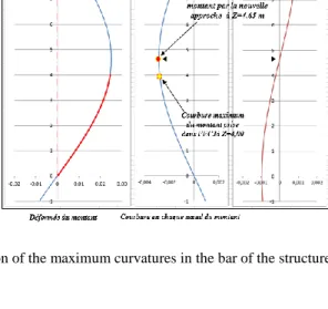
For the case of the feet articulated structure, there was obtained a maximum bending moment in the bar of the structure at Z = 4.00m, while in the reference bar, the maximum bending moment is located at Z = 4.65m. The calculation of the amplification factor in the method of eurocode 3 and 9 is obtained by comparing two points that are not located at the same position in one and the other bar, which is not justified on physically. There are other cases of structures where the gap between these two points is even more expressed.
Out to solve this, we have proposed a new approach. We set established a mathematical equation corresponding to the deformation of our structure. The sine term of the deformed allows us to mathematically reconstruct the deformed structure and to set its inflection points (Figure 2). The positioning of the inflection points allows us to build a virtual bar from which we will deduct either the maximum deformation (called "belly" maximum) or the "imaginary" maximum bending moment of the structure bars. This element (the maximum bending moment, curvature or maximum belly) buckling half height, will be compared, respectively, either to bending moment or to the curvature or "belly" up to the bar’s known reference. The proportionality factor Cnor will then be used to amplify the deformation of buckling mode (ŋcr) which lead to the definition of the desired single imperfection.
Indeed, the equation of the deformed shape of the structure is:
𝑋 = 𝐴 ∗ Cos (𝜋𝑧𝑙
𝑓) + 𝐵 ∗ 𝑆𝑖𝑛 (
𝜋𝑧
𝑙𝑓) + 𝐶𝑧 + 𝐷 [4]
From two eigenvectors of criticism of the first distorted way of elastic buckling, we can determine the coefficients A, B, C and D by writing expression UX displacements and RY rotations in two nodes of the structure. One obtains the following system of equations:
Figure 2. virtual bar
{ (cos (𝜋𝑙 𝐿𝑓) − 1) ∗ 𝐴 + (sin (𝜋 𝑙 𝐿𝑓) − 𝜋 𝑙 𝐿𝑓) ∗ 𝐵 = ∆ − 𝑅𝑌1∗ 𝑙 (−sin 𝜋𝑙 𝐿𝑓) ∗ 𝐴 + (cos (𝜋 𝑙 𝐿𝑓) − 1) ∗ 𝐵 = 𝑅𝑌2−𝑅𝑌1 𝜋 ∗ 𝐿𝑓 𝑊𝑖𝑡ℎ {∆= 𝑈𝑋𝑙 = 𝑍1 − 𝑍2 2− 𝑈𝑋1 [5]
The resolution of this system allows us to determine the unknowns À and B. The expression of the curvature at each point of the structure can be obtained by expressing the second derivative of the deformations of the bars. The curvature of the bar is given by the following expression:
𝑋𝑀" = −𝐴 ∗ ( 𝜋 𝑙𝑓) 2 ∗ 𝐶𝑜𝑠 (𝜋𝑍𝑀 𝑙𝑓 ) − 𝐵 ∗ ( 𝜋 𝑙𝑓) 2 ∗ 𝑆𝑖𝑛(𝜋𝑍𝑀 𝑙𝑓 ) [6]
Furthermore, the position of the maximum curvature point (maximum bending moment of the virtual amount of the bar of the structure) can be obtained mathematically by setting the derivative of the curvature equal to zero. Let then X '''= 0. This leads to the following expression:
𝑍𝑀= 𝑙𝑓+ ( 𝑙𝑓
𝜋) ∗ 𝐴𝑟𝑐𝑡𝑔( 𝐵
𝐴) [7]
Finally, using ZM, the maximum curvature, the maximum “imaginary” bending moment and the maximum belly of the most stressed rod of the structure can be determined. The latter being located halfway up from buckling, it is compared to the curvature respectively, the bending moment and the "belly" maximum of the reference bar.
3.2 Application to the study of an articulated gantry
In order to perceive the accuracy of the new approch, we studied four structures. Two gantry articulated and embedded, with two tours of 8 meter height. The following are for the gantry articulated.
Nodes UX RY Z
1 0,024524 0,001862 4
2 0,02325 0,003224 3,5
The coefficients A = 2.3 * 10-2 and B = 8.3 * 10-3
The coordinate of the maximum curvature point of the bar at ZM = 4.65 m The maximum curvature is obtained ŋ𝑴𝒂𝒙" = 𝟎. 𝟎𝟎𝟐𝟖𝟔 𝒎−𝟏
Graphically, we can see this :
Figure 3b. Position of the maximum curvatures in the bar of the structure and in the reference bar Table 1. Nodes displacements and rotations of the the studied structure
Indeed belly up can be observed eo 0.025135m for maximum curvature of 0.00286 m-1 located at 4.65 meters. Furthermore, the maximum curvature of the reference bar is located at mid-height buckling or 4.65 meters. Thus by the proposed new approach, we compare two points located at the same place in the two bars. This is the maximum bending moments in the reference bar and virtual bar, and then bends and "bellies" maximum.
Remark: As seen in Figure 4, to check the physical meaning of our approach, it was proposed to
superimpose the image of the deformed shape of the structure to the image of the theoretical deformed of our virtual bar. This overlap allows us to identify the critical section, section which may optionally be real or fictitious that is to say outside of the structure. Moreover, it also has access to the elements which one compared: the reference bar and virtual bar.
In our comparative study, calculations were performed on the Autodesk Robot Structural Analysis. We also studied three others structures, a gantry embedded of 4x4m, and two shoring towers including an 8x3m and the other of 8x1,5m (height x width). Our bars were of steel 32daN / mm2 in yield strength.
We summarized here the gap obtained after studying our structures, while taking for assumption that a gap of ±10% is not significant. For each structure, five cases were realized, the results obtained by each method of introduction of imperfections when calculating stresses are here resumed:
Case 1 2 3 4 5 common method of EC3 Entering the local and global distorted EC3 common method of equivalent charges Method EC3 (5.11) alternative method new Approach The method of EC9 Tower of 8x1,5 m 43,69 % 45,74 % 2,5 % 0% 4 % Tower of 8x3 m 42% 44% -1,4 % 0% 0,4 % Gantry of 4x4 m embedded in feet -8% -6,5% 0,3% 0% -0,4% Gantry of 4x4 m articulated in feet -26% -21% 1,42% 0% 2,13%
Figure 4 : Representation of the virtual bar superimposed on the
4. Observations
It is noticed that depending on if it is a structure where the first buckling mode is with fixed nodes (embedded gantry of table 2) or with moved nodes (tower and articulated gantry of table 2), the conventional common method of EC3 (case 1 of table 2), compared to those methods derived from the unique definition of imperfection, is safe for structure with first buckling mode with fixed nodes and underestimated in the other cases. For structures subject to sway buckling mode, the definition of a single imperfection allows to achieve safe and almost identical results to the results of the current method of Eurocode 3 when the buckling length is close to the length of diagram. Here we can refer to results of gantry of 4x4 m embedded in feet.
It is also observed during the course of the process of each method, those based on the definition of a single defect follows more closely the mechanical behavior of the structure. This observation is sustained by the results found for each studied structure by methods 3, 4 and 5. Those methods takes into account not only the geometrical aspects, but also the boundary conditions of the bars, intrinsic mechanicals properties and the load level of the structure. Current method of applying local and global imperfection (case 1, 2 of table 2) poses an ambiguity in the direction of taking into account local imperfection in the bars. Moreover, this method is substantially based on geometry and does not take account of the specific properties of the bars.
5. Conclusion
Our study focused on the comparison of methods considered structural imperfections in the calculation of scaffolding and shoring structures, since the latter have low critical loads as coefficients which are very vulnerable to the effects of second order. The objective is to be able to make a calculation that is both safe and economical. It was found that the method based on the unique imperfection has several advantages: it is simple and clear, easily applied and derived from a mechanical reasoning concrete. In addition, the current method, although seemingly simple, is full of many questions: the meaning of consideration of imperfections, the influence of the intrinsic properties of bars, etc.
References
[1] Ana M. Girão Coelho a,b,⁎, Pedro D. Simão a,c, M. Ahmer Wadee dImperfection sensitivity of column instability revisited. Journal of Constructional Steel Research 90 (2013) 265–282 [2]
Shabnam Shayan, Kim J.R. Rasmussen, Hao Zhang. On the modelling of initial geometric imperfections of steel frames in advanced analysis. Journal of Constructional Steel Research Volume 98, July 2014, Pages 167–177
[3] Maquoi Rondal J, Getting equation of the European buckling curves, Steel Construction, No. 1, 1978, page 17-30
[4] François Frey, Analysis of Structural and Continuum, Treaty of Civil Engineering from the Polytechnic School of Lausanne, Volume 2
[5] EN 1993-1-1. Eurocode 3: design of steel structures — part 1–1: general rules and rules for buildings. Brussels: European Committee for Standardization (CEN) 2005.
[6]
Eugen Chladný Magdalena Štujberová. Frames with unique global and local imperfection in the Shape of the elastic buckling mode (Part 1). DOI: 10.1002/stab.201310080, Stahlbau Volume 82, Issue 8, pages 609–617, August 2013
[7]
Eugen Chladný Magdalena Štujberová. Frames with unique global and local imperfection in the Shape of the elastic buckling mode (Part 2 · DOI: 10.1002/stab.201310082, Stahlbau Volume 82, Issue 9, pages 684–694, September 2013
[8]
Sébastien BAGUET, Stability thin structures and imperfection sensitivity by the asymptotic numerical method, doctoral thesis at the University of Aix-Marseille II, 30-50 October 2001 [9]
Eurocode 9: Design of aluminium structures - Part 1-1 : General structural rules. EN 1999 1-1 2007+A 1 :2009