Digital Ear Scanner:
Measuring the Compliance of the Ear by
Daniel Hernandez-Stewart B.S. Mechanical Engineering
Massachusetts Institute of Technology, 2007
ARCHIVES
MASSACHUSETTS INSTITUTE OF TECHNOLOGY
MAY 0
5
2010
LIBRARIES
SUBMITTED TO THE DEPARTMENT OF MECHANICAL ENGINEERING IN PARTIAL FULFILLMENT OF THE REQUIREMENTS FOR THE DEGREE OF
MASTER OF SCIENCE IN MECHANICAL ENGINEERING AT THE
MASSACHUSETTS INSTITUTE OF TECHNOLOGY FEBRUARY 2010
@2010 Massachusetts Institute of Technology. All rights reserved.
Signature of A uthor: ... ...
--Department of Mechanical Engineering
nu
Janu-ry 28, 2010
Certified by: ...
.---Doug Hart Professor of Mechanical Engineering
Thesis Supervisor Accepted by: ... ...
...---.---....
David E. Hardt Professor of Mechanical Engineering
Table of Contents
Table of Contents ... 2
Listing of Figures and Tables... 4
Nom enclature ... 8
A b stra ct ... 9
1. Introduction ... 10
1.1 M otivation ... 10
1.2 Current Problem s w ith Hearing Aids... 12
1.3 Dem ographics and M arket... 14
1.4 Traditional M anufacturing Procedure ... 24
1.5 Laser Scanning... 27
1.6 Jaw M ovem ent and Com pliance... 29
1.7 New Types of Hearing Aids ... 32
1.8 Existing 3-D Approaches... 33
1.9 Approach ... 35
2. Im aging w ith ERLIF and Absorption ... 36
2.1 ERLIF Fundam entals ... 36
2.2 Extension to Absorption M ethods... 43
2.3 1-D Absorption Calibration... 46
2.4 Discussion of Im aging Potential ... 49
2.5 3-D Stitching Sim ulation ... 51
3. Balloon Fabrication ... 54
3.1 Requirem ents ... 54
3.2 M aterial and M anufacturing M ethod Selection ... 56
3.4 Balloon Im provem ent ... 60
3.5 Adding Seals, Ports, and Rigid Plastic Backings... 66
3.6 Adding Fluorescence ... 72
3.7 Step by Step Procedures ... 75
4. Com pliance... 79
4.1 Infinite Cylinder of Skin M odel of the Ear ... 79
4.2 Early Latex Cylinder Compliance Data and Modeling ... 84
4.3 Com pliance Experim ental Setup ... 88
4.4 Com pliance and Jaw M ovem ent Data ... 92
4.5 Non-Dimensionalization and Comparison to Existing Data ... 96
5. Sum m ary and Conclusions ... 98
5.1 Accom plishm ents... 98
5.2 Future W ork ... 98
Acknow ledge m ents... 100
Listing of Figures and Tables
Table 1.1: Tabulated content analysis of the 348 letters received from owners of
hearing aids w ho do not use them . ... 13 Table 2.2: 2006 hearing loss statistics by sex, age, marital status, and education taken from NCHS (National Center for Health Statistics)... 14 Table 3.3: Hearing aid adoption rate statistics from MarkeTrak VII ... 16 Table 4.4: The out of pocket price per hearing aid and point of purchase from
1984-2 0 0 4 ... 18
Figure 1.1: The units of hearing aids sold per year... 18 Figure 1.2: Number of hearing impaired, includes future projection based on US census population projections coupled with hearing loss by age group. ... 19 Table 1.5: Hearing loss levels from Hearing Instrument Specialists (HIS) and Dispensing
Audiologists (DA) clients in 2005 and (2004)... 20 Figure 1.3: 5 m ain types of Hearing Aids ... 20 Table 1.6: Relative demand for various types of hearing aids 2006 -2008. ... 22 Figure 1.4: 2007 average reported prices of BTE (behind the ear), mBTE(mini behind the ear), ITE (in the ear), ITC (in the canal), and CIC (completely in the canal) by low end (LED), middle end (MLD) and high end (HED) with 95% confidence intervals... 23 Figure 1.5: The injection of impression material into an ear, and the removal of the im p ressio n ... 2 5
Figures 1.6a-i. The 9 steps in making a conventional hearing aid shell (prior to
assem bling electronic com ponents)... 26 Figure 1.7 The mean response of a sample of 12 CIC hearing aids with a given vent diam eter is show n above... 27 Figure 1.8: Desktop Laser Scanners ... 28
Figure 1.9: Point cloud (right) generated from this impression (left) ... 28
Figure 1.10: The increase in canal diameter between an open mouth low viscosity silicone and a closed mouth high viscosity silicone... 30
Figure 1.11: The increase in canal diameter between a closed mouth high viscosity silicone and a closed mouth low viscosity silicone... 31
Table 1.7: In the figure above it is clear that in their small trial compliant tipped hearing aids did quite well in term s of user-factors ... 33
Figure 2.1: A differential fluorescent elem ent... 37
Figure 2.2: Graph shows the intensity of the fluorescent emission of dye 1 and 2, as well as the ratio betw een them . ... 39
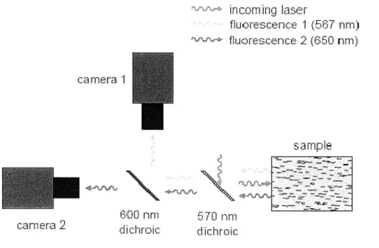
Figure 2.3: Experimental setup that can separate light into two small bands of w avelengths of interest. ... 40
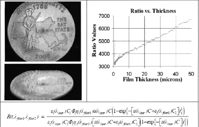
Figure 2.4: 3-D of coin scanned with ERLIF methods, and ERLIF calibration curve... 41
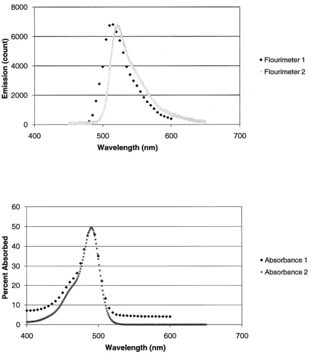
Figure 2.5: Quantitative absorption/emission profiles of Fluorescein as measured by tw o distinct fluorim eter instrum ents. ... 42
Figure 2.6: A representation of an absorption based depth scan setup ... 44
Figure 2.7: 1-D depth calibration experimental setup... 47
Figure 2.8: Preliminary 1-D depth calibration with flat, orange fluorescent target... 48
Figure 2.9: 1-D depth calibration with flat, Coumarin 153 impregnated membrane... 48
Figure 2.10: 1-D concentration calibration with flat, Coumarin 153 impregnated m e m b ran e ... 4 9 Figure 2.10: Solid model of foam assisted multiple region balloon concept. ... 50
Figure 2.11: 3-D point cloud of ear (left). Same 3-D point cloud cut up into six sections and then rotated, translated, and with xyz noise (right)... 52
Figure 2.12: Original 3-D point cloud minus stitched 3-D point cloud ... 52
Figure 3.1: Sample producible balloon geometries from Advanced Polymers... 56
Figure 3.2: Steps involved in blow m olding. ... 57
Figure 3.4: Early attempt at producing urethane balloons. Air bubbles are circled in b lack... 5 9
Figure 3.5: Early attempt at producing urethane balloons. ... 60
Figure 3.6: Air bubble free urethane balloon. ... 62
Figure 3.7: Hard plastic hearing aid shell to be used for mold as balloon. ... 62
Figure 3.8: A nub free balloon is shown in the picture above... 64
Figure 3.9: Thin brushed on balloon... 65
Figure 3.10: Successful, multiple brushed on layer, uniform ear shaped balloon... 66
Figure 3.11: Balloons sealed with O-rings and super glue... 67
Figure 3.12 Sheet of orange urethane for making balloon bases (left), and sample cuto ut base (right). ... 68
Figure 3.13: Base attached with silicone and removed... 69
Figure 3.14: Cyanoacrylate based method of adding base ... 69
Figure 3.15: Balloon base attached entirely with urethane ... 70
Figure 3.16: Balloon base with rigid plastic base... 71
Figure 3.17: Paint flaking off of a painted balloon... 72
Figure 3.18: Balloon made with layer of fluorescent paint trapped between two layers of u reth ane ... 73
Figure 3.19: Zebra striped pattern on stretched balloon made up of two layers of urethane with layer of fluorescent paint in between. ... 73
Figure 3.20: Balloon made with ground up fluorescent paint... 74
Figure 3.21: Balloon made with fluorescent orange powder... 75
Figure 3.22: Equipm ent needed... 76
Figure 4.1: Diagram of ear, taken from NIDCD fact sheet ... 80
Figure 4.2: Differential element in an axisymmetric coordinate system. ... 81
Figure 4.3: Dimensionless graph shows tendency of displacement divided by inner radius to stabilize as ratio of thickness divided by inner radius grows...84
Figure 4.5: Modeled compliance of latex sleeve. Model is very linear over range of inte re st... 8 6
Figure 4.6: Compliance graphs for balloon in free expansion and constrained by latex sle eve ... 8 6 Figure 4.7: Compliance graphs for balloon in free expansion and constrained by steel tu b e ... 8 7 Figure 4.8: Bulk compliance measurement experimental setup. The balloon, model ear, syringe, and pressure sensor are labeled above. The multimeter and power supply are
no t sh o w n . ... 8 8
Figure 4.9: Balloon with hard plastic base and cap. ... 89 Figure 4.10: Large syringe is used to fill the small syringe to eliminate air bubbles... 90 Figure 4.11: Large syringe with long probe tube is used to fill the balloon in order to elim inate air bubbles. ... 91 Figure 4.12: Internal pressure plotted as a function of volume of water injected for a balloon without hard cap in ear. (Average slope 4.73 psi/mL) ... 92 Figure 4.13: Internal pressure plotted as a function of volume of water injected for a balloon without hard cap outside of ear. (Average slope 1.9 psi/mL)... 93 Figure 4.14: Internal pressure plotted as a function of volume of water injected for a balloon with a hard cap in ear. (Average slope 7.8 psi/mL) ... 94 Figure 4.15: Internal pressure plotted as a function of volume of water injected for a balloon with hard cap outside of ear. (Average slope 3.0 psi/mL)... 95 Figure 4.16: Table of Young's modulus taken from Diridollou's paper [43]... 96 Figure 4.17: Data from Diridollou's paper on young's modulus of skin for men and
Nomenclature
a(A) camera sensitivity to a given wavelength
C effective two dye molar concentration
C, dye one molar concentration
C2 dye two molar concentration dV differential volume of fluid
dI differential element fluorescence
E(A) molar absorption coefficient for a given dye and wavelength
Je excitation illumination intensity
Io excitation illumination intensity constant (intensity at x=O)
A wavelength of light
Armin smallest wavelength that passes through red filter of rgb camera
Armax largest wavelength that passes through red filter of rgb camera
Agmin smallest wavelength that passes through green filter of rgb camera
Agmax largest wavelength that passes through green filter of rgb camera
rq dye's relative emission at give wavelength monitoring efficiency
0 quantum efficiency
R intensity of red/green
Digital Ear Scanner:
Measuring the Compliance of the Ear by
Daniel Hernandez-Stewart
Submitted to the Department of Mechanical Engineering on January 28, 2010 in partial fulfillment of the requirements for the degree of Master of Science in
Mechanical Engineering
Abstract
This paper seeks to resolve the biggest problem with hearing aids, their physical fit. By digitally scanning the ear canal and taking the dynamics of the ear into account the performance and comfort of a hearing aid can be greatly improved. Current optical techniques for 3-D imaging are too expensive to be implemented in the ear canal for the purpose of custom fitted hearing aids. A new absorption based optical technique is introduced, which is capable of generating three dimensional maps of an ear subjected to a varying pressure. Specifically a hearing aid can be constructed with allowances for the compliance of the ear and the distortions associated with jaw movement. It is shown that the information that can be captured with this new technique will be of value toward improving hearing aids, and that the hearing aid industry is ready to take advantage of a digital scanner. A one dimensional calibration was made, and qualitative 3-D data is shown. The imaging technique was implemented with much lower cost equipment then would be needed by other 3-D techniques such as interferometry. A technique for the laboratory manufacture of brushed on fluorescent balloons was presented that are suitable to be used by this imaging technique to measure the dynamics of the ear. The bulk compliance of a human ear in vitro was measured with a laboratory fabricated balloon.
Thesis Supervisor: Doug Hart
1. Introduction
This paper seeks to resolve the biggest problem with hearing aids, their physical fit. By digitally scanning the ear canal and taking the dynamics of the ear into account the
performance and comfort of a hearing aid can be greatly improved. Current optical techniques for 3-D imaging are too expensive to be implemented in the ear canal for the purpose of custom fitted hearing aids. A new absorption based optical technique is introduced, which is capable of generating three dimensional maps of an ear subjected to a varying pressure. It is possible to capture the dynamics of the ear in 3-D video and design a hearing aid that takes them into account. Specifically a hearing aid can be constructed with allowances for the compliance of the ear and the distortions associated with jaw movement. Additionally the development of a balloon fabrication methodology, which is necessary to implement the optical technique, is described as well as a simple method for measuring the bulk compliance of an ear. It is shown that the information that can be captured with this new technique will be of value toward improving hearing aids, and that the hearing aid industry is ready to take advantage of a digital scanner.
1.1 Motivation
Unlike glasses and contact lenses hearing aids have a social stigma attached to them. The problem with hearing aids is that they do not provide as robust a solution to hearing problems as exists for vision problems. Contacts, glasses, and laser eye surgery can restore almost perfect sight to all but the most visually impaired. These solutions have comfort, aesthetic, convenience, and cost tradeoffs that can fulfill the most demanding
of customers. Future fighter pilots, embarrassed teenagers, and aging retirees can all be satisfied by existing vision correction options.
In contrast hearing aids do not restore perfect hearing, run out of batteries, are considered unsightly, can be uncomfortable, fall out, and have a multitude of other issues. They are not main stream enough to be covered by most insurance even though hearing trouble is more prevalent than vision trouble. According to the National Center for Health Statistics [1], the percentage of American adults with hearing trouble, 17%, is significantly more than that than the percentage of adults with vision trouble, 11%. This percentage is likely to continue to rise because of noise induced hearing loss and an aging population.
In his "Hearing Aid Physical Fit: The Next Revolution," David Fabry [2] outlines the potential benefit of a digital scanner.
The most obvious way that digital technology may shift the paradigm is by ultimately eliminating the need for earmold impressions via direct ear scanning. The use of the 3D scanner may permit earmold/shell characteristics to be transmitted electronically to the manufacturer. Digital mechanics may be used to quantify and compensate for dynamic properties of the cartilaginous portion of the ear canal; this, in turn, will improve user comfort and reduce hearing aid feedback. Direct ear scanning may eliminate the need for earmold impressions. Digital mechanics may permit hearing aid acoustic characteristics to be assessed, modified, and optimized for individual ears. [2]
Other professionals are making similar hopeful statements, such as the editor of the Hearing Journal, David H. Kirkwood [3], in his article, "The Bright Promise of Direct Ear Scanning." Professionals in the hearing aid industry are eager to replace impression with direct ear scanning.
1.2 Current Problems with Hearing Aids
In order to ensure that a digital scanner could improve hearing aids it is necessary to examine the current issues with hearing aids. The various issues with hearing aids, most importantly performance, comfort, and background noise, have led to an all time low market penetration of 20.4% [4]. This low number arises from the fact that hearing aids are not effectively meeting the needs of the hearing impaired, and have not gained enough status to be widely covered by insurance. Kochkin's survey of 2720 hearing aid owners seeks the answer to the problem why "hearing aids are in the drawer." [4] His content analysis of the 348 letters received from owners of hearing aids who do not use them is shown in table 1.1.
1 Nos heeflitfren, he.a 1 nics 103 29.6% 261,510
2 lodgrouneJ b/cisy110UenM to 25.3% 229,401
S crforl it i5 181% 169,448
4 egvstiWe effectof A 30 10.9% 99,062
5 ?ri &11tW of repain 36 10.3% 93,848
d lnt edJ lp 28 1.0% 72,993
7 isloing dih brAkt 27 7.8% 70,306
I Sud qualbtyis poor 22 .3% 57,352
I JMimi -o 1W w 21 1.0% 54745
10 mwne ameind ieumrI 17 4.9% 44,317
11 Whiliqmg dAk 15 4.3% 39,103
12 WIOtWSWau/iam lng 14 4.0% 36,497
13 Pa sWnike [raM isMW l 5.2% 2,676
14 liig-freiwqe h rat lped 10 2.9% 26,06?
15 Siga f wig hwlgls 10 2.9% 26,069
16 Worin imied diwagm 9 24% 23,462
17 Promd hewng lo ne hulped 9 2.6% 23,462
13 Tooloud 8 2.3% 20,155
1 I soWryfeueshort 7 2.0% 18,246
20 Forgu t e 4 1.1% 10,428
21 aes notwok ols peus 4 1.1% 10,420
22 Monotrd dels joa 3 C.9% 7,821
23 Ovesaidegettdonm 3 C.9% 7,821
24 lave inidu 3 C.9% 7,821
25 Fmly pressered topurdum
I
3 .9% 7,82126 OMaimaetery 2 C.6% 5,214
27 tort sodul user 2 C.6% 5,214
23 Welkeerglug; I G.3% 2,60
2? Poa inchviy 1 .3% 2,6W
30 Gms iso hW 1 C.3% 2,60
31 Cn sifiedthm 1 1.3% 2,6W
Table 1.1: Tabulated content analysis of the 348 letters received from owners of hearing aids who do not use them. Most complaints can divided up into poor performance, comfort, and increased
background noise. [4]
A majority of complaints are related to performance or comfort. The most common complaint given is that the hearing aid has little benefit (29.6%). Additional performance related complaints included poor sound quality (6.3%) and feedback (4.3%). The second most prevalent issue for consumers, comfort, is the chief complaint for over a quarter of the population: 18.7% of consumers said fit and comfort specifically is their biggest issue with their hearing aid, and 10.9% cited negative side effects including blisters, rashes, itching, headaches, infections, problems chewing or swallowing, too much pressure. [4] It is not hard to see why hearing aid owners discontinue use given either poor performance of discomfort.
Comfort and performance are coupled are coupled by physical fit. To prevent leaking and feedback hearing aids need to create a seal in the ear canal. The correct amount of uniform pressure needs to be put on the surrounding tissues to create a seal and anchor the hearing aid to the ear without causing discomfort. A bad seal allows sound to leak past the hearing aid and mix out of phase, which degrades sound quality. Degrading sound quality requires higher amplification which requires more power and can decrease the efficacy of the hearing aid in background noise. The two most egregious problems consumers have with hearing aids ultimately are the result of a poorly fitting physical shell.
Complaints of increased background noise (25.3%), which are largely dependent on the users cognitive processing of sound, cannot be solved completely by improving fit. [4] Without a very large improvement in signal processing, hearing aids cannot hope to replace the brain's sound signal processing abilities. This problem is very frustrating for the hearing impaired, as the hearing aid amplifies both the signal and the background noise leaving them unable to hear in noisy environments.
This noteworthy difficulty is not addressed by the methods developed in this paper, but much progress can be made in improving hearing aids before this more complex problem is resolved. The most important problem with hearing aids is physical fit, which the new scanning technique is capable of solving. The next section explores the size and the makeup of the hearing loss problem.
1.3 Demographics and Market
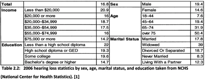
In order to understand the magnitude and composition of the hearing loss problem a brief study of demographics of hearing loss and the hearing aid market will be made in this section. In this study the following information will be considered: demographics, noise induced hearing loss, hearing aid adoption rates, hearing aid costs, number of hearing aids sold annually, growth, severity distribution, and types of hearing aids. A breakdown of hearing loss by sex, age, marital status, and education take from the National Center for Health Statistics is given in the table 1.2.
Total 16.8 Sex Male 19.4
Income Less than $20,000 20.9 Female 14.6
$20,000 or more 16 Age 18-44 7.6
$20,000-$34,999 18.7 45-64 19.4
$35,000-$54,999 17.5 65-74 31.9
$55,000-$74,999 16 over 75 50.4
$75,000 or more 14.2 Marital Status Married 17.8
Education Less than a high school diploma 22 Widowed 39
High school diploma or GED 19.3 Diwrced Or Separated 18.7
Some college 19.6 Never Married 8.3
Bachelors degree or higher 14.7 Living With a Partner 12.3 Table 2.2: 2006 hearing loss statistics by sex, age, marital status, and education taken from NCHS (National Center for Health Statistics). [1]
Many are aware that hearing worsens with age, but are unaware that over 50% percent of those over seventy five suffer from hearing loss. The effects of marital status can most likely be explained by correlation with age. For example, the group of widowed people is made up of older people on average than the married group. The effects of 14
sex, income, and education are smaller, but not negligible. Males with a poor education, and low income are the most prone to hearing loss.
The trends that are independent of age can be explained in part by noise induced hearing loss. According to the National Institute of Deafness and other Communication Disorders [5], NIDCD, "15 percent of Americans between the ages of 20 and 69 or 26 million Americans have high frequency hearing loss that may have been caused by exposure to loud sounds or noise at work or in leisure activities." Industrial hearing loss and lack of education concerning recreational noise is likely to be responsible for the trends of increased hearing loss in males and those with lower income or poor education. Many jobs that involved operating heavy noisy industrial equipment are held by poorly educated males. Noise induced hearing loss has gained more notoriety, which has recently led industry to respond to it with increased hearing protection. According to David H. Kirkwood [6], the military is associated with a large portion of hearing loss, with the Department of Veterans Affairs (VA) purchasing 16% of hearing aids in 2008. Additionally the number of VA purchased hearing aids went up by 9.2% between the third quarter of 2008 and 2007, while total hearing aid purchases declined 1.2%.
A very important characteristic of the hearing aid market is the market penetration, or the adoption rates. The overall adoption rate of approximately one fifth is indicative of hearing aids providing a poor solution to hearing impairment. Historical data for hearing instrument adoption rates broken down by sex, age, education, household income, employment status, metro size, and life stage is shown in the table below taken from Sergei Kochkin's [7] "MarkeTrak VII report. : Hearing Loss Population Tops 31 Million."
ass ng inemn un muesan
________=__.200tiD plw7W 1 f=IAI) pnft.9PW Awl&3fJ OllJF (171
F~~~~~fl- 323% M~ 13 M 5 i I2%
it" IM it4 116% L0W 2M
13-NM-4" asseMA aIasaMan a 21AuS ns 214 m1.7 4 5% 1% Em 5% 6.99 1177
Fem4p 22% 220% 227% 2 1.% 1P3% 211% 29AW
10.7p Nf% ee% Sa% 5-3% flf .7% tots. 45.4 ps 12A% e 0% 12%1% Its% 9. 1% 9.7
5-4M i 3.% W% 36A% a154% U5% 624% It
as+ PM Sam 419 ti .1% 4-% 16.3 69A% go.n
LaSSfMSn 32r ass at sAn a.,
S3-1*k 202% 6S3% 276% 27.1% 33% 2i%
S2ia Ma aISa f2J% MaM 21r
i30-I* 01% 90% f19$% 200% % 0% 224% 252%
to^- An3% WS 03% 300% WsA%
.Iy-M 202% 1i% 414% 7A% 172% 21 23-01as filn asas 15an nit f4an i.aaa
E3aipdAnNf 219% 351t 274%A 2f 52% 24% 0.
U.AS is"% 2LWt Vit V1% 101
Ig Sal dueg 21% 20A% 224,% 15% &9% 212%
- -20fl fIAtk - "3% Ufl 11M% 155 Ii
Cotpdgnu 223% 199% 1t% 112% 2D.0% 2135% 21.
Fdi iif sereft 1sa% e 0*aa obw tt- iM
Paame #Sml'b 212% 158% 1X% 11.4% 17.9% 1W3% 20
asnes an ton -ua mei sa isa
into 3'-% 362% 372% 374% 374% 37% 37 4
SMW L
sIIns n 2aMni7A
n% ten u2 IMat to2M an
72,Ma 2% nit 22.3% 2t % 21 nit % i.
1.a3.0RI...M2% 19A% - Ut 21% 11A% at% I
-sem-8* 11Mm usa* 1ss MW 112% -4%^ 1aa
Bgs-wn 124% 184% 143% 11% 125% 114% 17
..aa. an 1% AM u6m% WS% una8 17.
OiW 413I 458% 45.7% 432% 442% 44-2% 47.
.v.mg RN 2e% 27% 25.7 218% 21r% 202% 21.
iMR. -- - U.7% - a sta aan &M tWn7%
PWeM - YVAN 10.3% 91% 74% 7% 690% 79% a
-aWO tit% 1.7% in tuft &as
104% 10*% 174% Il.7% 1.0% 1A5 17.
Table 3.3: Hearing aid adoption rate statistics from MarkeTrak VII. [7] Overall adoption rates have held steady at approximately one fifth of the impaired population.
The overall adoption rate has held steady over this time span at approximately twenty
percent of the hearing impaired population. Adoption rates increase dramatically with
age. This trend is most likely a result of the severity of the hearing loss. Besides age
related effects life stage and employment status appear to have little effect on adoption rates. Adoption rates also appear independent of the size of the metro area. The effect of income and education are becoming less important factors in hearing aid adoption. However the adoption rates among the poorest and worst educated have fallen from
over 30% to only slightly higher than average at approximately 25%. Higher than average past adoption rates among the poor and uneducated and are not normal for a well functioning expensive medical device. This oddity might be explained by changes in hearing aid benefit coverage, increased hearing aid cost, or improved access to hearing testing.
Given the lack of widely available insurance coverage for hearing aids, cost might be expected to be more of an issue. The wealthy could be more sensitive to the social stigma associated with hearing aids. If current hearing aids were a good solution to the hearing loss problem one would expect significantly more overall market penetration, especially for those whom money was not an issue. Even though the price of a hearing aid does not seem central to adoption rates, it is important in characterizing the hearing aid market. The out of pocket expense of hearing aids as well as the percent covered by third parties is shown in the table 1.4, taken from Kochkin's report.
1984 1"$ 1991 It4 11M 000 4
ie1 ofhmero ftl p,.4f#" ("417) ("Wax fn667) 249 (MI*t) (O.$W
TId-party psmits M -"M'bVA 222% 1194% 17.1% 20,8% 247% 24A% 21. Tird-pry pasUnts (%) w VA 23.5% 21.7% 26.6% 30.2% 34.% 17.3
AWire aut-o-peS prftemwwnur Qs23 #01 3S $736 W17 $1 A7 31 (EAiag VA gfl)
STE S"? M5 SM7 565 SUM1 51,514
FTC $742 saw0 F71 $1,04 PAU $161
IE M4 $W1 73 $742 $1,97 $114
Mna lrn trunt ustuin ("4291 (350 M=493 (nM (653 (53 (n513 (=w5U3 ey rhWId pbaWt
A.ildogst 221% 4UAf 48.1% 4.3% 32.% 651% 6.0%
He*g aki eCIAM 6A% 48.6% 40% 44.7% 43.4% 2826% 35.9%
Mdtidacw 4.% 13% i2% 1% 1% .1% 10%
cow 6.9% 3.8% 2.9% 4.1% 1.7% 4.1% 7.1%
By $"No or wmU
---Huartig aM al atme 40.7% 30A% 36.5% 31.1% 30.5% 222% 37
Aiingrs le 21.3% 35.5% 36.5% 40.3% 41.3% 47.2% 24.
aft 52% 14% 1 % 2.0% 31% .
Hepial 21% 22% 2.2% 2.5% 1.5% 14
Er c* 9's1i" 6A% 141% 1M% 7.0% 7,1% 7Ii.
Fam(ydoc's ohflc 0.3% 13% 02% 0,6% 40% 02% 0.6%
Venus AMIbisaoM 1.W% 24b 3A 41% 1% 14.f
Mil ~i*e 2.1% 3.0% 0.% 2.5% 0.0% 3S% 54%
Depurnet sm 2A% 32% 4.7% 22% 2A% 2^% %
Home 6.3% .4% 7.3% 4.4% 3.7% 2.0% 0.%
M2- % 14% '.1% 1.% 1.%
Vfmle cub 2.0%
Olhe 15.0% 1.7% 2.0% 1.0% 3.4% 15% IA%
MENOW-Table 4.4: The out of pocket price per hearing aid and point of purchase from 1984-2004 The price has been rising steadily. [7]
The out of pocket price of a hearing aid has been on the rise. While the percent paid for by third parties excluding veterans' affairs has been steady, the percent Veteran's
Affairs (VA) has been responsible for has had a dramatic increase. VA is now responsible for 14.9% of the hearing aids distributed. Most hearing aids are purchased from
audiologists and hearing aid specialists, but new sources such as whole sale clubs have begun to distribute them.
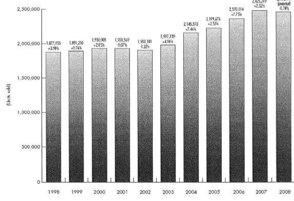
Another important piece of the hearing aid market is the number of units sold. The size of the hearing aid market in terms of units is shown in the figure 1.1 that comes from David H. Kirkwood's [6] report, "Economic turmoil threatens to reverse recent growth in the hearing aid market."
2,500,000 F-2,000,000 -1,8777 3 + 3.9Ui 2199?,78 2145,378 +2 5< 2 30.114 4715 2,425,2I9 Z*Na,4i 133- 4.18% 10 5 9 1 1594. -±20% 07; -1-.2 1 1 1,500,000 |-1,000,000 F 500,000 F
199 1 I 20I eI 20I 20I 20I 20I I I 2
1 998 1999 2000 2001 2002 2003 2004 2005 2006 2007 2008
The number sold was fairly steady from 1998 through 2003 at approximately 1.9 million units. From 2004-2008 this number grew to 2.4 million units. Current hearing aid market projections include significant growth, because the number of people affected by hearing loss is expected to rise. Projections for the growth of the incidence of hearing loss are shown in figure 1.2, taken from Kochkin's report.
60
C
20 -
-Figure 1.2: Number of hearing impaired, includes future projection based on US census population projections coupled with hearing loss by age group. [7]
The US census projects a steadily aging population. The hearing aid market is expected to grow significantly, because of this projection combined with the correlation between healing loss and age. The expected growth of the problem makes improving hearing aids even more important. As the population ages, severe hearing loss will also increase.
The severity of hearing impairment determines the reduction in quality of life, and the likelihood that an individual will seek out a solution. In the table below taken from Karl E. Strom's [9] "HR 2006 Dispenser Survey" statistics concerning hearing aid clients' level of hearing loss are shown.
Mild (<40 dBHL) 14% (12%) 18% (15%) 16% (14%) Moderate (40-70 dBHL) 52% (50%) 54% (55%) 53% (52%)
Severe (70-90 dBHL) 25% (30%) 21% (23%) 23% (26%)
Profound (>90 dIBHL) 9% (8%) 7 (7%) 804(8%)
Table 1.5: Hearing loss levels from Hearing Instrument Specialists (HIS) and Dispensing Audiologists (DA) clients in 2005 and (2004). [8]
People with severe and profound hearing loss are the most likely to seek out a solution, and make up approximately 30% of the hearing impaired. Mild and moderate hearing loss is often coped with, because of the current utility of hearing aids. Given a level of hearing loss different types of hearing aids are appropriate. Breaking the market down by hearing aid type gives insight into the needs of the hearing impaired. The main types are shown in the figure below, taken from National Institute on Deafness and Other Communication Disorders NIDCD [9].
Types of Hearing Aids
A, oir~ in -r a
Behind-thE-ear (BTE} omplee Iy-in-cara
(CIC
Figure 1.3: 5 main types of Hearing Aids [9].
Behind the ear hearing aids are best suited for those with severe hearing loss or low price needs, as they can provide large batteries and gains or economic electronics. In general as the hearing aids become smaller and deeper in the canal, they become more expensive, as the electronics need to be higher end. However, these hearing aids can have more problems with feedback because they have a shorter distance and as such time delay between input and output. In addition, the deeper impressions and shells go
"Mini" RTE In-the-ear (ITE) in-th, _ana10 T C}
0 OJT
into the sensitive bony region of the ear, which requires tighter tolerances to assure comfort without allowing sound to leak. An improved fitting technique could make deeper fitting impressions higher performance and more comfortable. Deeper in the canal sound transmission can be done more efficiently, reducing power requirements.
Studies like "The Hearing Aid Effect 2005: A Rigorous Test of the Visibility of New Hearing Aid Styles" by Johnson et all, [10] have studied the stigma against hearing aids in depth. The more noticeable the hearing aid the worse the stigma attached to it. The low visibility of smaller deeper fitting hearing aids is valuable to consumers. As hearing aid technology improves it is expected that the footprint of the electronics will continue to decrease. However, the progression to smaller deeper fitting hearing aids could be held up by the current impression based fitting process
An alternative to these four types of custom fit hearing aids, all of which require a custom impression, is the "mini" BTE or open fit hearing aid. The open fit hearing aids have been gaining popularity. In a survey by Earl E. Johnson [11] of 418 audiologists, 41.6% of hearing aids sold were mini open fit behind the ear devices. Customers like open fit hearing aids because they can walk out of the audiologist's office with one after their first visit, and they mitigate problems like occlusion, jaw movement, and poor retention (problems which will be explained further later). Additionally, open fit hearing aids save audiologist times by not requiring an impression, but are only suitable for minor and moderate hearing loss (less than 65 DB), because of the open path for feedback. The demand for hearing aids by type is taken from Kirkwood [6] and shown in table 1.6.
% OF ALL INSTRUMENTS SOI
2008 2008
(Jan.-Sept.) Completely-In-the-canal (CIC) analog 4053
CIC digital signal processing (DSP) 158.784
All CIC 162837
hn-the-canal analog 7905
In-the-canal DSP 186,842
All In-the-canal 194,747
Half-shell In-the-ear (ITE) analog 3221 Half-shell ITE DSP 132,318
All half-shell ITE 135,539
Full-shell analog ITE 23,671
Full-shell DSP ITE 266,342
All full-shell ITE 290,013
Other ITE analog 5073
Other ITE DSP 14,362
All other ITE 19,435
Total ITE analog 43,923
Total ITE DSP 758,648
All ITEs 802,571
Behind-tfe-ear (BTE) analog 21,213
BTE DSP 1,021,084
Total BTE 1,042,297
Total all styles analog 65,136 Total all styles digital 1,779,732
Total all styles 1,844,868
0.2% 8.6% 0.4% 10.1% 10.% 0.2% 7.2% 7.3% 1.3% 14.4% 15.7/O 0.3% 0.8% 1.1% 2.4% 41.0% 43.5% 1.1% 55.3% 56.5% 3.5% 96.5% 100.0% 2007 0.9% 8.9% 9.8% 1.1% 11.3% 12.4% 0.5% 7.0% 7.5% 2.4% 15.0% 17.4% 0.7% 0.8% 1.5% 5.6% 43.0/ 48.6% 2.5% 48.9% 51.4% 8.1% 91.9% 100.0% 2006 0.6% 10.2% 10% 1.1% 13.3% 14.4% 0.3% 8.4% 8.7% 2.4% 17.9% 20.3% 0.8% 1.1% 1.9% 5.2% 50.9% 56.1% 3.1% 40.8% 43.% 8.3% 91.7% 100% Table 1.6: Relative demand for various types of hearing aids 2006 -2008. [6]
The most important trend illustrated in the figure above is a rise in BTE demand, which comes mostly from growth in the market for open fit hearing aids. The number of open fit versus regular fit can be tracked by evaluating the batteries the BTE's were equipped with. In 2007 they made up 37.2% of the BTE hearing aids sold, and in Q1-Q3 of 2008 they made up 42.2% of the BTE hearing aids. [6] Open fit hearing aids were responsible for 2.5% growth in the total market on their own. They have lead to a reduction in the market share of all the other hearing aids. The hearing aid that has lost the most ground is the ITE, in the trend towards miniaturization. Hearing aids are also becoming increasing digital, with analog devices down by more than a 50% is just a single year.
UNITS SOLD TYPE
To help finish quantifying the market presence of these different styles the average price of low end, middle end, and high end BTE (behind the ear), mBTE(mini behind the ear), ITE (in the ear), ITC (in the canal), and CIC (completely in the canal) are shown in the figure below taken from Earl E. Johnson's [12] dispenser survey report, "Despite having more advanced features, hearing aids hold line on retail price."
$0 $500 $1,000 $1,500 $2,000 $2,500 $3,000 $3,500 Analog $857 LE D BTE $1,149 LE D mBTE $1,318 LE D ITE $1,204 LE D ITC $1,309 LE D CIC $1,364 ML D BTE $1,843 ML D nmBTE $1,861 ML D ITE Si ,840 ML D ITC $2,147 ML D CIC $2,023 HE D BTE S2,609 IIE D mBTE S2,672 HE D ITE $2,686 HE D ITC $2,744 HE D CIC $2,860
Figure 1.4: 2007 average reported prices of BTE (behind the ear), mBTE(mini behind the ear), ITE (in the ear), ITC (in the canal), and CIC (completely in the canal) by low end (LED), middle end (MLD) and high end (HED) with 95% confidence intervals. [12]
In general as shown above smaller hearing aids are more expensive, with CIC being the smallest and most expensive and the BTE being the largest and cheapest. The gap between low and high end is nearly a factor of 3 for a given type of hearing aid.
The most important point to take away from this section is that the hearing loss problem is big and growing. The existing solutions are unsatisfactory to a larger
percentage of the affected population. Open fit hearing aids provide a good solution for many who have moderate hearing loss and their introduction has caused a lot growth. An improvement to fitted hearing aids would most likely lead to similar growth, and pave the way towards less visible, more comfortable, better performing hearing aids. Those who have purchased open fitted hearing aids will eventually need a custom fitted one that is just as functional. It is not just Fabry [2] and Kirkwood [3] calling for an improvement in fitting techniques, the market is as well. Now that the market has been characterized and shown favorable to the proposed technology, the next section will turn its attention to the traditional fitting technique of hearing aids.
1.4 Traditional Manufacturing Procedure
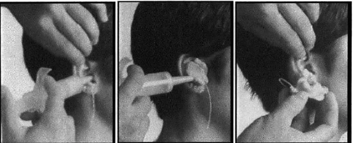
The current approach to fitting for both traditional and digital manufacture is based on injecting a deformable setting substance, often silicone based into the ear. It is a process that requires significant skill, thirty minutes of an audiologist's time, can cause significant discomfort to the patient, and is shown below in figure 1.5.
Figure 1.5: The injection of impression material into an ear, and the removal of the impression.
Before the silicone can be injected any excess hair must be removed and the ear must be cleaned of wax. A foam plug is then placed deep in canal to protect ear drum. The impression material is mixed and put in large syringe. The syringe is used to skillfully fill the ear with resin in order to make a good impression. Ten minutes later, after the material has hardened the impression is popped out, sometimes painfully. The whole process is sometimes uncomfortable for the patient. Every audiologist has their own methodology, concerning what type of silicone to use, how to fill the ear with resin, and what position to put the patient's mouth in.
This complicated manual procedure has a poor track record with quality control. In discussions with manufacturers it was learned that as many as 30% of hearing aids need to be remade, because they do not fit the user properly. The impression process is variable, but even when the impression is made well the hearing aid can fit poorly because of un-captured dynamics. Too tight of a fit can be painful, while too loose of a fit will lead the hearing aid to fall out and add undesired acoustic effects.
Creating a hearing aid from this impression traditionally requires significant post processing. The impression is coated with wax to reduce surface imperfection and to give the extra material needed for a seal, a reverse mold is produced (investment
casting) and in this mold the final shell material is poured. The detailed steps in traditional manufacture are outlined by Richard Corte et all, [13] in figure 1.6.
Figures 1.6a-i. The 9 steps in making a conventional hearing aid shell (prior to assembling electronic components): a) A cast of the impression is made; b) The ear impression is trimmed to the model size; c) The impression is dipped in wax; d) A hydrocolloid cast of the impression; e) Acrylic resin is poured into the hydrocolloid cast; f) Excess acrylic resin is drained from the hydrocolloid cast; g) The faceplate end of the shell is trimmed; h) The vent is laid into the shell; i) The finished shell is ready for electronics.
[13]
The majority of shells are made by this fully manual process, and as a result the quality of the fit depends largely on the skill of the technician who acts almost as an artisan. This process is time, labor and therefore cost intensive.
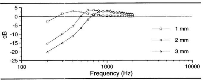
Hearing aids often include vents to allow moisture to escape the ear and reduce low frequency booming. A loose fit acts as a vent, but of an uncontrolled, sometimes very large size. In an 8mm canal an uncontrolled vent can be quite large compared to a normal vent, 1-2 mm in diameter. The frequency response of different size vents in figure 1.7 illustrates the effect an uncontrolled vent could have, taken from Stuart et all, 26
[14] "The effect of venting on in-the-ear, in-the-canal, and completely in-the-canal hearing aid shell frequency responses: real-ear measures."
Mean Response of
CIC
hearing aids with given vent diameter
5-0 -5M -c----1 mm
O
-10-2 mm -15 -20 -- 3 mm -25-100 1000 10000
Frequency (Hz)
Figure 1.7 The mean response of a sample of 12 CIC hearing aids with a given vent diameter is shown above. [14]
As shown above, increasing the area of the vent in an uncontrolled manner due to poor fit can have a dramatic effect of the frequency response of the hearing aid. The expense of the remakes led the hearing aid industry to respond to the fit problem with a new technology. Laser scanning of the impressions has been introduced which will be discussed in the next section.
1.5 Laser Scanning
The hearing aid industry has begun regularly using what are called laser shell or digital shell technologies. The process begins by taking a scan of the impression using a desktop machine shown in figure 1.8 in the images taken from Sullivan's [15] paper, "Scan/print vs. invest/pour shell-making technologies for CIC hearing aid fitting"
Figure 1.8: Desktop Laser Scanners [15]
Selected Laser Sintering (SLS), Stereo Lithographic Apparatus (SLA), and Digital Light Processing (DLP) are the three technologies used for producing hearing aids. The scanning is highly accurate and can measure the impression to 50 micron accuracy. They are expensive to produce and are often provided to audiologists by hearing aid companies, such as Siemens. The scanner generates a point cloud such as the one shown below from the impression also taken from Sullivan's paper.
Figure 1.9: Point cloud (right) generated from this impression (left). [15]
When laser scanning began, the hearing aids created were the exact replicas of the impression. The manufacturers were confused because at first more remakes were necessary than have been previously by the traditional method of manufacture. As a result, manufacturers brought parts of the manual process in to the digital one to improve it. Wax of slightly varying thickness was replaced with a perfect digital offset. Trimming of the impression was replaced with virtual trimming. However, after these
steps the gains in the quality of hearing aids coming out of digital methods in terms of physical fit were not as large as the manufactures had hoped.
The recent trend towards scanning and printing of hearing aids has led the industry to be ready to print hearing aids from digital data. 3-D systems made a press release on May 14, 2009, announcing a new hearing aid manufacturing system the V-Flash HA 230 Manufacturing System. The V-Flash platform is the first commercially available 3-D printer under $10,000. The existence of a cheap desktop platform for making hearing aid from digital data was a crucial step in making the market ready to benefit from a direct ear scanner.
Now that the digital scan/print process has reached a plateau, it is safe to say that while it may have improved repeatability, lead times, and cost, it has not drastically improved physical fit though there was room for radical improvement. The laser scan's tolerances are very good, but it is probably much more accurate than the ear impression. Measuring the ear impression in a highly accurate fashion is not worthwhile if the impression itself is inaccurate. If this was the only problem a more accurate single digital in ear scan might be sufficient to solve the physical fit problem. However, there are two other important issues, jaw induced canal distortion and ear compliance. No single 3-D model or impression can capture the data needed to make a hearing aid that accounts for these phenomena.
1.6 Jaw Movement and Compliance
The process of capturing jaw movement and compliance is similar in that both require multiple sets of three dimensional data to be fully captured. Currently, the only way that such data has been captured experimentally is by taking two impressions with the mouth opened and closed (for jaw movement) and with high-viscosity and low-viscosity
silicone (for compliance). The high-viscosity silicone pushes harder against the ear and makes a slightly larger impression.
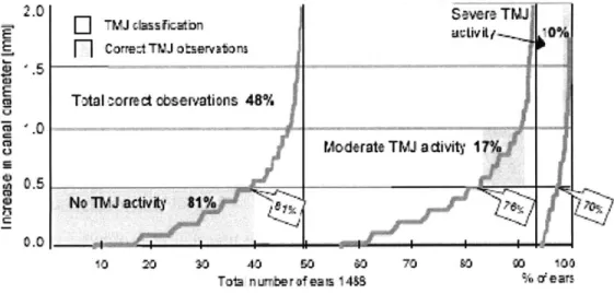
This multiple impression technique is reasonable to carry out experimentally, but not in general practice because of the added cost of the extra impressions. The study by Chester Pirzanski [16] titled "Ear canal dynamics: Facts versus perception," shows that both jaw movement and compliance can lead to large distortions of the ear, up to 2 mm, (ear canals are on the order of 10mm), and that the size of the effects cannot be predicted accurately by trained audiologist. In figure 1.10 the growth in the canal associated with the jaw's temporomandibular joint (TMJ) is shown.
2.0 TMJ dassrcarn Savre TMJ
F]
corre:tTW otseivaions Total correct observations 48%Moderate TMJ adivity I
.
No TIM J aivy 1% 0.0
10 20 so 40 so 0 70 io 00 100
Tota nurnter of ea s 1488 % dears
Figure 1.10: The increase in canal diameter between an open mouth low viscosity silicone and a closed mouth high viscosity silicone. [16]
Approximately 80% of ears have less than a .5 mm increase in canal diameter, but other 20% are likely to have problems with fit if there TMJ activity isn't accounted for. 1 mm of growth on a ten millimeter canal can easily cause an uncontrolled vent or a loose fitting hearing aid. Either one of these issues will probably lead to a remake of the hearing aid or discontinued use. One question addressed in Pirzanski's paper was whether or not audiologists could categorize the mouth dynamics without additional
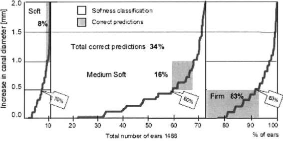
impressions. This solution would be cost effective, but audiologists could only correctly categorize the mouth dynamics into these three categories 48% of the time. Data for an equally important hearing aid fit problem, compliance, is shown in figure 11, taken from Pirzanski [16].
1.5
1.0
0.5
10 20 30 40 50 60 70 0 90 100
Total number of ears 1488 % of ears
Figure 1.11: The increase in canal diameter between a closed mouth high viscosity silicone and a closed mouth low viscosity silicone. [16]
If the compliance of the ear is not taken into account, serious problems with fit may arise. A soft ear could easily lead to a loose fit and bad seal, and a firm ear can easily lead to pain and discomfort, especially when combined with TMJ activity. Audiologists could only correctly categorize the compliance into these three categories 34% of the time.
Given these two data sets, it becomes clear why the impression/scan and traditional manufacturing methods often lead to problems with fit. Hearing aids will regularly be too tight on some people with very firm ears, too loose on some people with very soft ears, or lose performance or comfort while opening the mouth to talk or chew. An important goal of this paper is to introduce a method of scanning ears that would cost
effectively allow for the manufacturers to gain access to information about the compliance and TMJ distortions of an ear. It may not be immediately clear how to use the additional 3-D data to improve hearing aid fit, but when it can be effectively utilized it should put an end to the issues with hearing aid fit that laser scan/print has failed to solve. A recently introduced hearing aid technology that attempts to address some of these problems with fit, compliant tipped hearing aids; the limitations of this solution are discussed in the next section.
1.7 New Types of Hearing Aids
Compliant tipped hearing aids are quite new and have only recently come into the literature in February 2008. Compliant tipped hearing aids make use of slow recovery foam with the goal of mitigating fit problems like jaw movement, poor retention, and comfort. Compliant tipped hearing aids have done well in studies, but are subject to the limitation of being for moderate hearing loss. As a result they only solve a problem that for the most part has been solved by open fit hearing aids.
The tips need to be changed every 10-14 days, but may still be cost effective since they have a low initial cost and reduce the time needed for fitting with an audiologist. They are currently manufactured by one manufacturer, Hearing Components Inc, and have only published data for one small trial with 30 patients. The user-factor results are promising and are shown in figure 1.7 taken from Smith et all [17] paper, "Study finds compliant eartips can be used instead of custom earmolds."
Benefit 56.7. (12.5) 55.0, (11.6)
disal 26.3, (10.1) 26.5, (10.8)
Satisfaction 57.3, (12.2) 58.1, (10.2)
Table 1.7: In the figure above it is clear that in their small trial compliant tipped hearing aids did quite well in terms of user-factors. [17]
They are similar to open fit hearing aids in that they save audiologist times by not needing an impression, and are only suitable for moderate hearing loss. However, open fit hearing aids are already providing a good solution for this subset of the hearing impaired. Given their performance limitations compliant tipped hearing aids do not reduce the need to improve the physical fit of custom hearing aids.
1.8 Existing 3-D Approaches
3-D imaging is a vast and varied field. For the most part 3-D imaging solutions are very expensive. Good literature reviews of the work in 3-D imaging can be found in the following three papers. [18, 19, 20] Despite the vast amount of research devoted to machine vision, not very much work has been put into measuring objects dimensionally similar to the ear canal from the inside. The earliest 3-D measuring instruments
required contact with the surface. However, physical measurement is impractical with certain fragile materials. The two standard non-contact approaches rely on either triangulation or time of flight.
Non-contact optical scanners fall into the categories of passive and active. Passive scanners use triangulation between two or more cameras, resolving depth in the same manner as the human visual system [18]. The biggest technical hurdle of stereo and multi-view systems is the correspondence problem. Daniel Scharstein evaluates several algorithms performance in this field [21]. Another major goal for a 3-D system is to be able to measure in real time. Recently real time stereo correlation has been
implemented on ATI Radeon 9800 GPU [22]. Correspondence algorithms make use of local and global matching of textures, shapes, and shadows. Stereo systems need too much space to fit in the ear canal, because a stereo system requires two cameras separated by an appropriate distance.
Active non-contact scanners can bypass the correspondence problem by using active illumination. Active methods, like passive methods, rely on triangulation. The first active scanner used a camera to track a moving single laser point. This process mirrored the physical coordinate measuring machine by building up the model one point at a
time. A similar but faster approach was invented that relied on a plane of laser light. This technique removed a dimension of the scan and is widely used today. Another method that makes use of lasers is interferometry, which combines two lasers offset by a distance.
The newest non-contact method uses a digital projector instead of a laser and is known as structured light. Digital projectors can make complex depth dependant patterns that can be picked up on the camera. A lot of work has been put into the problem of
optimizing the projected patterns. [23] Like passive methods, active methods require more space than is available in the ear canal because of the need for a light source, camera, and triangulation. Additionally active methods are currently too expensive for fabricating custom fit hearing aids.
The time of flight method is based on measuring the time it takes for the emitted pulse to be reflected back to the sensor. The accuracy is limited by how well time can be
resolved. For example an accuracy of one centimeter requires a time resolution of 66 picoseconds. [19] Time of flight is typically used to measure large objects like buildings because it is inexpensive and is relatively inaccurate.
None of the current 3-D imaging methods are appropriate for measuring the ear canal. Triangulation methods take up too much space and are too expensive. Time of flight is not accurate enough. MRI's were used by Olivera [24] scan ear canals, but are too expensive to be suitable for making hearing aids. Given the goal of making a cheap, robust system that could scan an ear canal, none of the existing technologies were suitable.
1.9 Approach
In order to push development forward the problem of taking three dimensional data on the ear, it was decomposed into two main problems: measuring the compliance of an ear and developing a technique capable of imaging the ear. These two issues are discussed in their own sections. They were split up in order to allow concurrent work on the two, with the hope that both solutions could eventually be combined. Another sub problem is the stitching of 3-D data, which is also treated on its own briefly in the imaging section. In the subsequent imaging section ERLIF (emission reabsorbtion laser induced fluorescence) and an absorption based imaging technique inspired by it will be introduced and described mathematically.
2. Imaging with ERLIF and Absorption
When the goal of 3-dimensionally scanning the ear was first being pursued, the planned technique was ERLIF (emission reabsorption laser induced fluorescence), which can be used to measure a film thickness. This technique was introduced by Coppeta, J., et. al. [25] in 1998 under the name of DELIF (dual emission laser induced fluorescence) and expanded upon by Carlos Hidrovo and Doug Hart in a series of papers between 2000 and 2004. This section will develop the equations to explain ERLIF and the absorption based imaging technique it inspired, as well as show the resulting calibration curves. The fundamentals of this technique are explained in the next section.
2.1 ERLIF Fundamentals
ERLIF is an extension of Laser Induced Fluorescence (LIF). In LIF a light source is used to excite fluorescent tracers. LIF has been used as a qualitative tool used to visualize particles of interest by Ayala et al [26] and Joffe et al [27], and as a flow tracer by Georgiev and Alden [28], Kovacs [29], and Thirouard and Hart [30]. It is difficult to use as a quantitive tool, because of variation in illumination, surface reflectivity, color, and translucency as well as vignetting effects from tracer emission. The core idea behind ERLIF is to cancel out these variations taking a ratio of measured intensities between two fluorescent frequencies. The mathematics that show it to be a variation free approach are developed in Hidrovo and Hart's papers, and will be treated briefly in this section. Hidrovo [31] begins with the differential fluid element shown in figure 2.1.
Area, A
1A
emission
I
1VVolume
element,
AV
=
AAx
excitation
Figure 2.1: A differential fluorescent element. [25]
Given this fluid element of concentration C, volume dV, molar absorption coefficient EF(A), quantum efficiency , illuminated by a uniform intensity e, the amount of light captured by a camera pixel with monitoring efficiency, , from this differential volume,
dh; is given by:
dI = (Ie(A)C(PdV. (1)
Monitoring efficiency, the percentage of light that is captured by the camera, remains essentially constant over the area of interest. The first modification that needs to be made is to consider the absorption of light by other elements of fluid, by including the Beer-Lambert's Law of Absorption [32]. e is modeled to exponentially decay with, x, with A, as the strength or illumination at x=O,
I,
= IeA[-e(A)Cx]. (2)This modification is critical to the success of the ratiometric approach as it used absorbance to make the intensity seen at the CCD depend of the depth of the fluid in a predictable manner. If a pair of dyes is used in which the absorption spectrum of dye 2 overlaps the emission spectrum of dye one, a thickness dependent behavior between
the ratio of the intensities of their emissions will emerge. The expected intensity at the peak fluorescence for dye 1 and 2 needs to take into account absorption of the laser frequency by dye one and dye two and the emission of the first dye by the second dye
Once these modifications have been made the expected intensity for both peaks is the result of integrating modified versions of equation (1) with respect to x. This process leads to the following equations developed in Hidrovo and Harts [31] on DELIF film measurement, with an addition in nomenclature qdye, (dye's relative emission at give wavelength)
i I Vo Ei(AC1@1191(Af ilteri)(1-eXp[-[ E(Alaser)C+E(Afilter1 02]X)(3
E(Alaser)C+E(Afilter1)C2
if 2 = (IoE2(A)C29
I7
2 2(Afilter2)(1-exp{-[ E(Alaser)C] (}E (Alaser) C
The ratio of the two intensities is calculated below and can be seen to be thickness dependent, but not excitation dependent
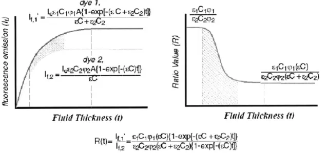
R = E1(A) C151771 (Afilter) (1-exp(-[ E(Alaser)C+E(Afilterl)C2]X} E2(A)C2( 2 2(filter 2)(1-eXP{-[ E(Aaser)C]X}
It is hard to predict the behavior of this ratio by inspection. The quantities in equations 3-5 were graphed as a function of film thickness in figure 2.1 taken from Hidrovo and Hart's [33] paper on ERLIF in 2001.