Magnetization of carbon-coated ferromagnetic nanoclusters
determined by electron holography
S. Seraphina)
Department of Materials Science and Engineering, University of Arizona, Tucson, Arizona 85721
C. Beelib)
Centre Interde´partemental de Microscopie Electronique, Ecole Polytechnique Fe´de´rale de Lausanne, CH-1015 Lausanne, Switzerland
J-M. Bonard
Institut de Physique Expe´rimentale, Ecole Polytechnique Fe´de´rale de Lausanne, CH-1015 Lausanne, Switzerland
J. Jiaoc)
Department of Materials Science and Engineering, University of Arizona, Tucson, Arizona 85721
P.A. Stadelmann
Centre Interde´partemental de Microscopie Electronique, Ecole Polytechnique Fe´de´rale de Lausanne, CH-1015 Lausanne, Switzerland
A. Chaˆtelain
Institut de Physique Expe´rimentale, Ecole Polytechnique Fe´de´rale de Lausanne, CH-1015 Lausanne, Switzerland
(Received 30 November 1998; accepted 2 April 1999)
The magnetic properties of carbon-coated Co and Ni nanoparticles aligned in chains were determined using transmission electron holography. The measurements of the phase change of the electron wave due to the magnetization of the sample were performed. The ratio of remnant magnetization to bulk saturation magnetization Mr/ Ms of Co decreased from 53% to 16% and of Ni decreased from 70% to 30% as the particle diameter increased from 25 to 90 nm. It was evident that the inhomogenous magnetic configurations could diminish the stray field of the particles. After being exposed to a 2-Tesla external magnetic field, the Mr/ Msof Co increased by 45% from the original values with the same dependency on the particle size. The Mr/ Msof Ni particles, on the other hand, increased only 10%. The increased magnetization could be attributed to the merging of small domains into larger ones after the exposure to the external magnetic field. The validity of the interpretation of the holograms was established by simulation.
I. INTRODUCTION
Ferromagnetism is a collective phenomenon which is caused by the mutual interaction of many atoms and their electrons. As a consequence, the size, composition, mi-crostructure, and morphology of a ferromagnetic sample influence its magnetic properties. Various models have been used to interpret different aspects of ferromag-netism.1 The interaction can be considered limited to nearest neighbors, placing emphasis on the properties of
the atoms involved (Heisenberg model). Other models require that the itinerant properties of the electrons are considered (bandstructure model). The reality lies in be-tween both models, dependent on the size and micro-structure of the sample.
The understanding gained new inputs by the possibil-ity to prepare small clusters of ferromagnetic materials with less than a thousand atoms and dimensions ap-proaching the nanometer.2 The number of atoms con-tained in these clusters is small enough to consider only a fraction of them belonging to the bulklike core while the sizable remainder is affected by their closeness to the surface. It can be expected that one or the other ferro-magnetic mechanism is predominantly present in either the core or the surface region. If the fractional contribu-tion of surface and bulk varies, the corresponding mag-netic behavior of the clusters will change. Therefore,
a)
Address all correspondence to this author. e-mail: [email protected]
b)
Present address: Laboratory of Solid State Physics, ETH Zurich, CH-8093 Zurich, Switzerland.
c)
Present address: Department of Physics, Portland State Univer-sity, Portland, OR 97207, U.S.A.
their magnetic properties will vary with the diameter of the particles and the arrangement of atoms as determined by the crystal structure. Surface features such as oxida-tion or encapsulaoxida-tion will also change the fracoxida-tional con-tribution of the bulk versus surface regions.
The field gained additional input by the discovery of methods to encapsulate ferromagnetic metals and their alloys into cages of multilayer graphite.3–8The interest in these encaged nanoscale magnets was stimulated by their technological promise. Recording technologies in par-ticular are searching for very fine-grained magnetic ma-terials that could be tailored in their magnetic properties while being resistant to oxidation. It was shown that the graphite cages can protect the ferromagnetic cores against oxidation during longterm immersion in acids.4,11 A second, more fundamental reason was that the limited size and number of atoms in a particle could support novel physical properties that were not stable in the mac-roscopic bulk. Indeed, crystalline structures of the metal encapsulates were observed in temperature regions that were not representative of the bulk-phase diagram. For example, carbon-coated Co nanoparticles were found to have face-centered-cubic (fcc). phase instead of hexagonal-close-packed (hcp) which is usually stable in the bulk at room temperature.4 The presence and the effect of the tightly confining graphite cage could transform inner car-bon shells into diamond,9 to give another particularly striking example.
It is possible to control the diameter of carbon-coated nanoparticles of ferromagnetic elements by varying the preparation conditions such as the size of the anodic metal pool, the jet flow rate, and the static pressure in the carbon-arc-based method of preparation.10,11This raised the question of how their magnetic properties were af-fected by their size or encapsulation. Several studies were devoted to answering this question. Samples of dif-ferent composition, structure, and morphology were pre-pared, their sizes and composition characterized by electron microscopy and spectroscopy, and their integral magnetic properties measured, as a function of tempera-ture.4,7,11,12 It was confirmed that the encapsulated par-ticles were indeed ferromagnets which makes them interesting from a technological point of view. Although several explanations could be cited for the interpretation of the results, a decision among them was complicated by a lack of information on the magnetic properties of in-dividual particles because only integral magnetic meas-urements were performed up to now on the samples. The only report on the magnetic characterization of indi-vidual carbon-coated nanoparticles (Co, Ni, Dy) was fo-cused on ellipsoidal particles of 15–30 nm long diameter.13 The results were obtained by superconduct-ing quantum interference magnetometry specially de-signed for micrometer-size characterization and showed that the nanoparticles are of a single-domain character.
A recently developed technique for measuring magne-tization of the particles of small dimensions is electron holography. The technique allows the measurement of the phase change of an electron wave due to the magne-tization of the sample.14,15Thin nanowires of ferromag-netic materials have been characterized using electron holography with respect to their domain structure as a function of diameter and length-to-diameter ratio.16,17 The study presented here uses electron holography to determine the magnetization of spherical carbon-coated Co and Ni particles as a function of their diameters (25 to 90 nm). The principles and practical aspects of the elec-tron holography are presented in the following sections. The limitations of resolution are discussed and simula-tions are presented that support the statements made con-cerning the magnetization of the individual particles. II. EXPERIMENTAL PROCEDURES
A. Preparation of carbon-coated cobalt and nickel particles
The carbon-coated nanoparticles were prepared in a modified arc discharge chamber4with two vertical elec-trodes facing each other. A graphite rod of 6.5 mm diam-eter was located on the top as the cathode. The anode was a graphite crucible with an inner diameter of 25 mm, filled with either cobalt or nickel. A jet of helium gas at a velocity of approximately 30 m/s was introduced in the direction perpendicular to the electrodes. The arc dis-charge was set at 22 V, 175 A in dc current under a helium pressure of 300 Torr. The deposit was collected and examined in scanning and transmission electron mi-croscopes (SEM/ TEM). It consisted of only spherical carbon-coated metal particles without any tubular or other unwanted structures [Fig. 1(a)]. A typical TEM image shown in Fig. 1(b) reveals that most of the par-ticles are coated with a thin graphite layer (inset). Our samples consisted of a mixture of completely coated par-ticles and a fraction of incompletely coated parpar-ticles.
To prepare samples for electron holography, the de-posit was dispersed in ethanol and sonicated for 5 min. The suspension was spread on a standard TEM grid which was covered with a continuous thin film of amor-phous carbon without holes. Two sets of samples for each metal were studied: as deposited and after magne-tization in a 2-Tesla magnetic field applied in a direction parallel to the grid plane. Only the chains of particles that were parallel to the applied magnetic field were investi-gated in electron holography on the same day for Ni and 2 days later for Co. About 15 to 20 chains of each sample type were studied.
B. Electron holography
Electron holography is one of the few techniques available for measuring the microscopic magnetization.
The principle is based on the fact that the electron wave transmitted through a magnetic sample changes phase depending on the sample magnetization and its thickness. For spherical particles, the phase change due to the sample thickness will be symmetric around the particle center, while the phase change due to the magnetization will be asymmetric across the particle. The phase change can be retrieved from a hologram obtained by overlap-ping the wave scattered by the sample with the (partially) coherent reference wave (Fig. 2). The holograms were reconstructed to retrieve both the amplitude and phase of a wave scattered by the sample. The phase image recon-structed from the hologram corresponds to the phase
dif-ference,⌬, between object and reference waves. For a magnetic field, the phase difference is proportional to the integral of the magnetic-flux density B over an area be-tween reference beam and object beam along the direc-tion of the optical axis of the microscope as displayed in Fig. 2. In determining the magnetic properties of the particles, it will be most useful to obtain the magnetic field lines inside the particles. This requires a TEM with an additional Lorentz lens to provide the hologram reso-lution sufficient to resolve the radius of the particles.18 Alternatively, one can measure the magnetic field outside the particles, i.e., the leakage field. However, the holo-gram resolution and the phase sensitivity in our set-up (see below) are insufficient to reliably measure the leak-age field of a single isolated particle smaller than 50 nm. Therefore, we selected particles aligned in linear chains. The clusters of particles are avoided in our measurement because the magnetization of individual particles will partially cancel each other resulting in a reduction of the leakage field. Furthermore, the inner mean potential of these small particles is negligible in the phase-change retrieval because of the low resolution of our holograms. For a chain of nanoparticles, the flux of B through the chain itself corresponds to the total flux leaking from the FIG. 1. (a) SEM image of Ni particles illustrating the size and the
shape of the particles. (b) TEM image of Ni particles showing the graphitic coating (inset).
FIG. 2. Schematic drawing of the experimental set up for recording electron holograms of magnetic specimens. For a magnetic sample, the phase difference⌬ is proportional to the magnetic flux density B integrated over an area limited by a reference beam and an object beam along the direction of the optical axis of the microscope.
chain and can thus be measured as a phase change by electron holography. The phase change ⌬ across the chain of the particles is proportional to the total leakage flux of the chain (0MS ). It is given by:
⌬ ⳱ (2e /h)0MS, (1)
where S is the cross-sectional area of the particle, M its magnetization, and 0 is the magnetic field constant (4 × 10⁻⁷Vs/Am). The magnetization M which is the magnetic moment of the remnant state Mr can be deter-mined when the value of ⌬ is measured from the re-constructed phase image retrieved from the holograms, while S is calculated from the diameter of the particle measured from a conventional TEM image. We deter-mined Mrfor particles of various diameters. To illustrate the dependence of the magnetization on the particle size, the Mrvalues were normalized with respect to the bulk-saturation magnetization, Ms(5.1 × 10⁵A/m for Ni and 1.4 × 10⁶A/m for Co). This is acceptable because the saturation magnetization of the particles is not by itself dependent on the size of the particles once they are big-ger than 20 nm.11While the saturation magnetization of the particles rises strongly for diameters between 5 and 20 nm, it levels off at 85% of the bulk value once the particles have a diameter greater than 20 nm, as is the case in this study.
It should be pointed out that electron holography can detect only the in-plane component of magnetization along the chain and not the vertical component. How-ever, the fact that the particles arrange themselves in a linear chain indicates that the direction of the magnetiza-tion is along the chain and in the plane of measurement. Furthermore, this procedure usually gives magnetization values too small if there is partial flux closure inside the particles as in the case of multiple domain particles. On the other hand, it will give too large a value for small particles (smaller than 50 nm) that are attached between two larger particles. The measurement will be more re-liable if the adjacent particles have similar size which is usually the case in our measurement.
The experimental micrographs were obtained using a Hitachi HF-2000 FEG equipped with a rotatable electro-static biprism. A negative voltage (−7 to −9 V) was ap-plied to the biprism fiber to superimpose the reference wave and the object wave. The width of the interference region depended on the voltage applied to the biprism fiber and was typically 2 to 3 mm. The holograms were recorded using a Gatan retractable slow-scan CCD cam-era. To study the remnant magnetization state of the sample, the objective lens current was switched off. The specimen had to be imaged with the first intermediate lens while the remaining three lenses were fully excited to reach the maximum possible magnification in this con-figuration (1100 times on the CCD camera at an
operat-ing voltage of 200 kV). To further magnify the final image, the operating voltage of the microscope was re-duced to 100 kV because the given lens strength is more effective on the slower electrons. The magnification amounted to 2800 times on the CCD camera.16,17 The remnant magnetization of the particles was investigated by TEM electron holography at 100 kV while their di-ameters were measured by conventional TEM at 200 kV. In our case, the hologram spatial resolution was around 100 nm (which corresponds to 2 or 3 times the interfer-ence fringe spacing) and the phase resolution was ± 0.2 radian. To demonstrate that the obtainable resolution is sufficient to determine the magnetization of the carbon-coated nanoparticles of 25 to 90 nm, a series of simula-tions was performed. The interpretation of the phase maps is supported by these simulations presented below.
III. RESULTS AND DISCUSSION
A. Magnetization of carbon-coated Ni and Co nanoparticles
In each type of Ni or Co sample, 15 to 20 holograms were taken. Each phase image reconstructed from a ho-logram provided 8 to 12 values of the phase change depending on the shape of the chains and the quality of holograms. Overall, about 120 particles in each sample were analyzed. The particles were classified with respect to their diameters in sections of 5 nm width centered at 25, 30, . . . , 60 nm for Co case, and the mean magneti-zation of each diameter range was reported. For Ni par-ticles, sections of 10 nm width centered at 35, 45, . . . , 85 nm were used.
Figure 3(a) shows an image of a Ni chain; Fig. 3(b) the reconstructed phase image with three positions labeled 1, 2, and 3 where the phase change was measured and plot-ted as shown in Fig. 3(c). The phase changes across the chain were measured to be −2.1, −1.6, and 3.9 radian at location 1, 2, and 3, respectively. At 1, the value of S in Eq. (1) was determined using a particle diameter of 95 nm. From Eq. (1) with⌬ ⳱ −2.1 rad, M was calcu-lated to be 1.5 × 10⁵A/m which is about 30% of the bulk saturation magnetization of Ni. The same calculation shows that at location 2, the phase change of −1.6 rad across a 70 nm particle corresponds to 2.2 × 10⁵A/m (43% of the bulk saturation magnetization) and at loca-tion 3, the phase change of +3.9 rad across a 95-nm par-ticle has 2.9 × 10⁵A/m (57% of the bulk saturation magnetization). Note that the phase changes the sign from negative values at locations 1 and 2 to a positive value at location 3. It indicates a reversal of magnetic moment along the chain. Fig. 4 shows another example of the sign reversal [indicated by arrows in Fig. 4(a)] along a chain of Co particles. The direction of these magnetic moments along the chain was found to change
mostly at locations where particles agglomerate together. Figures 4(b) and 4(c) are the amplitude image and the phase image reconstructed from a hologram. Figure 4(d) displays four phase-profiles across the chain and three
reversals of magnetization. Note that the spatial resolu-tion of the hologram can be estimated by comparison of the amplitude image, Fig. 4(b) with the TEM image, Fig. 4(a).
FIG. 3. (a) Image of Ni nanoparticle chains used for holography. (b) Phase map with 1, 2, and 3 indicating the lines along which the phase was plotted and displayed in (c).
FIG. 4. (a) Chain of Co particles exhibiting reversals of the magnetization along the chain. Arrows indicate the direction of magnetization. (b) Amplitude image. (c) Phase image. The reversal of the magnetization is derived from the sign reversal of the phase change across the chain displayed by profiles in (d).
Figure 5 shows the relative magnetization of carbon-coated Ni nanoparticles as a function of their diameters. The plot reveals that in the diameter range of 30 to 90 nm the larger the particles the lower the magnetization. The magnetization of the small particles (30–40 nm diameter) is 75% ± 10%, dropping to 32% ± 2% for particles of 80-to 90-nm diameter. Compared 80-to the integral value of 30% obtained from the macroscopic measurement of magnetization by VSM technique,4the results from elec-tron holography provide more detailed information on the magnetization of the particles. After exposure to the 2-Tesla external magnetic field, the magnetization of the particles increased about 10% with the same dependency on the particle size. It can be reasoned that the external field induced the small domains to merge into larger ones, so the internal flux closure is reduced and the leak-age of magnetic flux is increased.
Magnetization of carbon-coated Co nanoparticles shows the same trend as Ni: the larger the particles the lower the magnetization (Fig. 6). However, the ratio of the remnant to bulk saturation magnetization of as-deposited Co is lower than that of Ni. The highest rela-tive magnetization obtained in this sample is around 55% ± 6% and the lowest magnetization is 16% ± 6%. (It should be noted that the bulk saturation magnetization of Co is 1.4 × 10⁶A/m and of Ni is 5.1 × 10⁵A/m). This rather low magnetization of Co particles may be due to the presence of multiple domains even in the smallest par-ticles observed, a carbon coating layer and the fcc phase in which cobalt is present here. The fcc is about 5% inferior in its magnetic property at room temperature to the bulk hcp phase in Co. The decrease of magnetization in larger particles may be due to the flux closure between domains inside the bigger particles. Consequently, the outside magnetic leakage is reduced. Large particles may
also have their individual magnetic moments out of the plane and not along the chain direction. This effect will reduce the detectable phase shift in the hologram because the electron holography technique can determine only the in-plane component of the magnetic flux. After being exposed to the 2-Tesla external magnetic field, the mag-netization of Co particles increases 45% compared to the as-deposited particles with a similar dependence on par-ticle size. The larger increase (45%) of the magnetization after exposure to the external field in Co compared to only 10% in Ni can be related to an observed higher defect density in Co particles. Because Co particles are fcc, most defects are likely to be stacking faults which results in a locally hcp phase (for example, intrinsic stacking fault ABCABABCABC or extrinsic stacking fault ABCBABCABC). These defects in as-deposited particles cause pinning of opposite magnetic spins result-ing in multiple domain particles. Obviously, the 2-Tesla external field was strong enough to align the magnetic spin across the defects and reduced the domain bound-aries. This effect lasted at least 2 days judging from the time of the exposure to the time of the holography analysis.
B. Interpretation of phase maps
To understand the influence of the limited spatial reso-lution on the reconstructed phase maps, a series of simu-lations has been performed. They address basically three different aspects of the measurements. First, we show that the evaluation of the magnetization from an external leakage field is meaningful to the extent that the magne-tization can be expressed in the form of the dipole arrows shown in Fig. 4(a), independent of the size of the par-ticles and the possible presence of multiple magnetic
FIG. 5. Relative magnetization Mr/ Msof carbon-coated Ni particles
as a function of particle diameter using Ms⳱ 5.1 × 10
5A/m. Exposure
to an external magnetic field (2 Tesla) increases the magnetization of the particles by approximately 10%.
FIG. 6. Relative magnetization Mr/ Msof carbon-coated Co particles
as a function of particle diameter using Ms⳱ 1.4 × 10
6A/m. Exposure
to an external magnetic field (2 Tesla) increases the magnetization of the particles by approximately 45%.
domains inside the particle. Second, the inversion of the direction of magnetization is directly observable. Third, the limited resolution of the holograms does not interfere with an accurate statement about the phase shift due to the magnetic flux. The following simulations will sub-stantiate all three claims. The simulations were carried out by Mathematica and HoloWorks19 software. Math-ematica was used to stimulate the phase maps which were subsequently used to calculate with HoloWorks a set of holograms with different spatial-resolution values. In the simulation of the electron holograms the influence of a perturbed reference wave due to the far field (leak-age field) of the magnetic sample was taken into account. The reconstruction of these holograms will be presented in the following paragraphs.
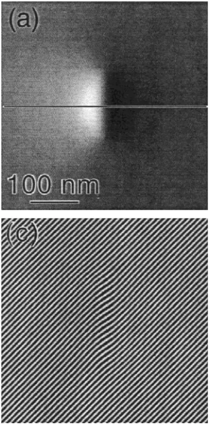
Real magnetic (monodomain) particles have a far field similar to a dipole field, however, the field variations near the particle or across the particle differ significantly from a dipole field, i.e., it does not have the mathemat-ical discontinuity across the dipole line. Figure 7(a) presents the ideal phase map of a small cylindrical par-ticle with 150 nm in length and 60 nm in diameter, which is comparable to a segment of our nanoparticle chains. A magnetization corresponding to 1.3 × 10⁶A/m (approxi-mately the bulk value of cobalt) has been assumed. The corresponding phase profile across the particle is shown in Fig. 7(b). The phase varies continuously across the particle without any abrupt phase changes and reveals a total phase shift of 7 rad. A simulated hologram with high resolution [Fig. 7(c)], i.e., with fine interference fringes of 9 nm distance, provides a reconstructed phase map which correctly represents the continuous-phase change across the particle. Because the total phase change across the particle exceeds 2, the phase is “wrapped” in the reconstructed phase map [Fig. 7(d)], which represents the phase in the interval from − to . The closed dis-continuity line which bounds the kidney-shaped, black region in Fig. 7(d) corresponds to a 2-discontinuity line. This phase map, therefore, can easily be “un-wrapped” by adding 2 to all the data points inside the black region bounded by the discontinuity line to recon-struct the physical-phase information. The phase profile [Fig. 7(e)] across the particle shows a −2 and a +2 phase discontinuity when crossing the 2 discontinuity line. Nevertheless, the close correspondence to the origi-nal-phase profile in Fig. 7(b) can be recognized. By add-ing 2 to the part between the two 2-phase discontinuities, a total phase change of 6.8 ± 0.1 rad can be measured from this profile.
In contrast, the hologram presented in Fig. 7(f) has low spatial resolution (interference fringe spacing of 34 nm). The interference fringes running across the particle are strongly bent, because the magnetic flux enclosed be-tween two adjacent fringes is much larger than in the case of the fine interference fringes of Fig. 7(c). The 2
dis-continuity line in the corresponding reconstructed phase map [Fig. 7(g)] is not a closed loop and thus, does not allow a correct unwrapping of the phase information (i.e., without the help of further knowledge on the physi-cal nature of the specimen). Nevertheless, the total phase change across the particle can be measured with a phase profile [Fig. 7(h)]. The measured value of 6.8 ± 0.2 rad is reasonably close to the value obtained in Fig. 7(e) and compares well with the original value. However, the measurement uncertainty is slightly larger than in the case of the profile in Fig. 7(e).
These examples have shown that a low spatial resolu-tion of the electron hologram leads to phase maps with certain artifacts, especially if the phase changes more than 2 over a short distance. The measurement of the total phase change is nevertheless possible if care is taken to correctly interpret the 2 discontinuity. Gener-ally, the phase maps with low spatial resolution lead to a reduced sensitivity of the phase measurement. However, the present simulations indicate that the conditions used in our experiments still allow a reasonable measurement accuracy.
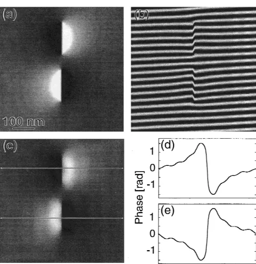
The orientation of the magnetization along the chain of particles has been found to change direction (shown in Figs. 3 and 4). In the following simulation, we illustrate that the observation of the reversal of magnetization di-rection along the chain is straightforward. In Fig. 8(a), two identical magnetic segments with opposite magneti-zation direction are presented in an ideal phase map. The opposite direction of the magnetization can be recog-nized by the opposite side of the bright contrast with respect to the magnetic dipoles. In this simulation, each magnetic segment is 150 nm long, 60 nm in diameter, and the magnetization is 5.5 × 10⁵A/m (slightly larger than the bulk value for nickel). This results in a total phase change of 3 rad across the magnetic segment. The corresponding hologram [Fig. 8(b)] has been simulated with an interference fringe spacing of 34 nm. The inter-ference lines are shifted in opposite directions because of the opposite magnetization direction of the segments. Be-cause the shift can be very weak in experimental holo-grams this cannot be observed as easily as in the presented simulations. The reversal of the magnetization direction is, however, revealed in the reconstructed phase map [Fig. 8(c)], because the basic pattern of Fig. 8(a) is clearly recovered. The phase profiles across the two seg-ments are presented in Figs. 8(d) and 8(e), respectively. While the phase profile in Fig. 8(d) displays a phase change from approximately +1.5 to −1.5 rad, the phase profile in Fig. 8(e) gives the opposite phase change. This is another clear indication that the direction of the mag-netization is opposite for these two segments. It is shown that the reversal of magnetization is an obvious observa-tion against any possible artifact caused by the experi-mental set-up or conditions.
FIG. 7. (a) Ideal phase map of a small cylindrical particle with 150 nm in length, 60 nm in diameter, and a magnetization of 1.3 × 10⁶A/m.
(b) The phase profile across the particle showing the continuous phase change with a total shift of 7 rad. (c) Simulated hologram with high spatial resolution of 9 nm interference fringe spacing. (d) Reconstructed phase map showing a 2 discontinuity line surrounding the kidney-shaped black region. (e) Phase profile across the particle. By adding 2 to the part between the two 2 phase discontinuities a total phase change of 6.8 ± 0.1 rad can be measured. (f ) Simulated hologram with low resolution of 35 nm interference fringe spacing. (g) Reconstructed phase map showing a 2 discontinuity line that is not a closed loop. (h) Phase profile across the particle revealing a total phase shift of 6.8 ± 0.2 rad. All figures have the same scale as Fig. 7(a).
IV. CONCLUSIONS
The observations reported above lead to the following conclusions:
(1) Electron holography by transmissions electron microscopy can be used to determine the remnant mag-netization of individual carbon-coated nanoparticles of Co and Ni attached to each other in chains. The magne-tization of the sample is observed through the phase change of the electron wave transmitted through the sample. Simulations of the phase maps show that the conditions used in the experiments allow a reasonable measurement accuracy.
(2) The direction of magnetization is usually along the chain. Changes in the magnetic direction can be derived by the reversal of a positive to a negative change of the electron-wave phase. Polarization of the particle chains caused by exposure to a strong external magnetic field results in an increase of the observed remnant
magneti-zation. It is speculated that the increased magnetization is due to the merging of domains into larger ones. Differ-ences between Co and Ni can be explained by the greater tendency of Co nanoparticles to contain stacking faults. (3) Above a particle diameter of 25 nm, the relative magnetization decreases from 53% to 16% of the bulk value in Co as the size of the particle increases to 70 nm. Corresponding values for Ni are 70% and 30% for the diameter ranging from 30 to 90 nm. The tendency to form multidomain structures resulting in flux closure in-side the bigger particles may provide an explanation.
ACKNOWLEDGMENTS
We acknowledge the financial support of the U.S. Na-tional Science Foundation (Grant No. DMR 9302353), the Swiss National Science Foundation, and the Ecole Polytechnique Fe´de´rale de Lausanne, Switzerland. FIG. 8. (a) Ideal phase map of two identical magnetic segments with opposite magnetization direction. Each magnetic segment is 150 nm long, 60 nm in diameter, and the magnetization is 5.5 × 10⁵A/m. (b) Simulated hologram with an interference fringe spacing of 34 nm. The interference
lines are shifted in opposite directions because of the opposite magnetization direction of the segments. (c) Reconstructed phase map. (d) and (e) The phase profiles across the two segments. While the phase profile in Fig. 8(d) displays a phase change of −3 rad, the phase profile in Fig. 8(e) gives the opposite phase change of +3 rad.
REFERENCES
1. D.C. Mattis, The Theory of Magnetism, 2nd ed. (Springer-Verlag, Berlin, 1988).
2. I.M.L. Billas, A. Chaˆtelain, and W.A. de Heer, Science 265, 1682 (1994).
3. J-H. Hwang, V.P. Dravid, M.H. Teng, J.J. Host, B.R. Elliott, D.L. Johnson, and T.O. Mason, J. Mater. Res. 12, 1076 (1997). 4. J Jiao and S. Seraphin, J. Appl. Phys. 80, 103 (1996).
5. Y. Saito, M. Okuda, T. Yoshikawa, A. Kasuya, and Y. Nishina, J. Phys. Chem. 98, 6696 (1994).
6. S.A. Majetich, J.O. Artman, M.E. McHenry, N.T. Nuhfer, and S.W. Staley, Phys. Rev. B 48, 16845 (1993).
7. J.J. Host, J.A. Block, K. Parvin, V.P. Dravid, J. L. Alpers, T. Sezen, and R. LaDuca, J. Appl. Phys. 83, 793 (1998). 8. K. Lafdi, A. Chin, N. Ali, and J.F. Despres, J. Appl. Phys. 79,
6007 (1996).
9. F. Banhart, J. Appl. Phys. 81, 3440 (1997).
10. J. Jiao and S. Seraphin, J. Appl. Phys. 83, 2442 (1998).
11. J-M. Bonard, S. Seraphin, C. Beeli, J-E. Wegrowe, T. Sto¨ckli, J. Jiao, P.A. Stadelmann, and A. Chaˆtelain Electrochem. Soc. Proc. 193 (San Diego, CA, 1998), pp. 794–807.
12. T. Hayashi, S. Hirono, M. Tomita, and S. Umemura, Nature 381, 772 (1996).
13. W. Wernsdorfer, E. Bonet Orozco, K. Hasselbach, A. Benoit, B. Barbara, N. Demoncy, A. Loiseau, H. Pascard, and D. Mailly, Phys. Rev. Lett. 78, 1791 (1997).
14. A. Tonomura, Electron Holography, Springer Series in Optical Sciences 70, (Springer, Berlin, 1993).
15. A. Tonomura, L.F. Allard, G. Pozzi, D.C. Joy, and Y.A. Ono, Electron Holography (Elsevier, Amsterdam, 1995).
16. C. Beeli, B. Doudin, J-Ph. Ansermet, P.A. Stadelmann, J. Magn. Magn. Mater. 164, 77 (1996).
17. C. Beeli, B. Doudin, J-Ph. Ansermet, P.A. Stadelmann, Ultrami-croscopy 67, 143 (1997).
18. R.E. Dunin-Borkowski, M.R. McCartney, B. Kardynal, D.J. Smith, J. Appl. Phys. 84, 374 (1998).