Publisher’s version / Version de l'éditeur:
ECS Transactions, 7, 1, pp. 781-786, 2007
READ THESE TERMS AND CONDITIONS CAREFULLY BEFORE USING THIS WEBSITE.
https://nrc-publications.canada.ca/eng/copyright
Vous avez des questions? Nous pouvons vous aider. Pour communiquer directement avec un auteur, consultez la
première page de la revue dans laquelle son article a été publié afin de trouver ses coordonnées. Si vous n’arrivez pas à les repérer, communiquez avec nous à PublicationsArchive-ArchivesPublications@nrc-cnrc.gc.ca.
Questions? Contact the NRC Publications Archive team at
PublicationsArchive-ArchivesPublications@nrc-cnrc.gc.ca. If you wish to email the authors directly, please see the first page of the publication for their contact information.
NRC Publications Archive
Archives des publications du CNRC
This publication could be one of several versions: author’s original, accepted manuscript or the publisher’s version. / La version de cette publication peut être l’une des suivantes : la version prépublication de l’auteur, la version acceptée du manuscrit ou la version de l’éditeur.
For the publisher’s version, please access the DOI link below./ Pour consulter la version de l’éditeur, utilisez le lien DOI ci-dessous.
https://doi.org/10.1149/1.2729166
Access and use of this website and the material on it are subject to the Terms and Conditions set forth at
Fabrication of a metal-supported ceria cell by wet powder spray and its characterization at intermediate temperatures
Oishi, N.; Yoo, Y.; Davidson, I.
https://publications-cnrc.canada.ca/fra/droits
L’accès à ce site Web et l’utilisation de son contenu sont assujettis aux conditions présentées dans le site LISEZ CES CONDITIONS ATTENTIVEMENT AVANT D’UTILISER CE SITE WEB.
NRC Publications Record / Notice d'Archives des publications de CNRC: https://nrc-publications.canada.ca/eng/view/object/?id=1f5a15db-3920-485f-9793-0e64f9fe8794 https://publications-cnrc.canada.ca/fra/voir/objet/?id=1f5a15db-3920-485f-9793-0e64f9fe8794
Fabrication of a metal-supported ceria cell by wet powder spray and its characterization at intermediate temperatures
N. Oishi, Y. Yoo and I. Davidson
Institute for Chemical Process and Environmental Technology National Research Council Canada, Ottawa, Ontario K1A 0R6, Canada
A tri-layer comprising a lanthanum strontium cobalt iron perovskite cathode, a doped ceria electrolyte and a nickel ceria cermet anode was fabricated on a porous stainless steel substrate by a series of processing steps involving wet powder spraying, lamination and sintering, and was tested with humidified 50 % hydrogen in argon supplied to anode and air supplied to cathode at intermediate temperatures of 650 and 600 °C. Open circuit voltage showed relatively lower values, below 0.75 V, however the cell was found to deliver higher current densities, over 1 A/cm2, and achieved a maximum power density of over 450 mW/cm2 at 650 °C. It was found that the cathode accounted for most of the polarization resistance and that the anode polarization was less influential to the ceria cell tested.
Backgrounds
We have been focusing on wet processing technologies involving colloidal ceramics suspensions and sintering stages that would allow us to fabricate metal supported solid oxide fuel cells at much lower costs. It had been shown that bi-layers of a doped ceria electrolyte and a nickel cermet anode can be fabricated on stainless steel substrates by using a series of processing technologies involving wet powder spraying (1), lamination and sintering processes (2). In order to evaluate the feasibility of this processing route for fabrication of metal-supported cells, a tri-layer comprising, from the top downwards, a cathode, an electrolyte and an anode, was fabricated on a stainless steel substrate having a porous structure, and was tested as a fuel cell using humidified 50 % hydrogen in argon as the fuel at intermediate temperatures in the range of 600 to 650 °C.
Experimental
Fabrication and characterization of a tri-layer on a porous metal substrate
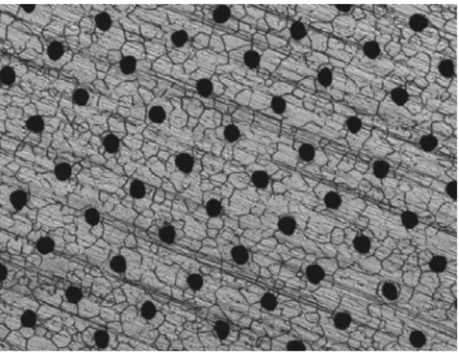
For the metal substrate, a ferritic stainless steel (SUS-447J: nominally, Fe-30Cr-2Mo) was chosen, and was machined to disks with a thickness of 250 µm and a diameter of 18 mm. Porous structure was subsequently introduced into the disk by laser machining process with/without an etching process. Figure 1 shows the surface optical micrograph of one of porous metal substrates prepared; black dots spaced over the surface are holes, which are around 20 µm in diameter and 75 µm apart in a simple square structure. The one-directional scratches seen are due to the cold-rolling process, grains of stainless steel can also be observed in the micrograph.
Figure 1. An optical micrograph of a porous metal surface (640 µm x 480 µm). An anode suspension containing 65 wt% NiO – 35 wt% Ce0.8Sm0.2O2 was first
sprayed onto a porous metal substrate, followed by an electrolyte suspension containing Ce0.9Gd0.1O2. An appearance of a sprayed anode on substrate and a sprayed electrolyte on
anode is shown in Figure 2. Zirconium was incorporated into the anode suspension as a sintering inhibitor, while iron was added into the electrolyte suspension as a sintering aid (3). It should be noted that no polymeric agents were added into the colloidal ceramic suspensions.
Sprayed electrolyte on anode
Sprayed anode on substrate
Metal substrate
18 mm
Sprayed electrolyte on anode
Sprayed anode on substrate
Metal substrate
18 mm
Figure 2. An appearance of sprayed layers on a metal substrate.
The weakly bonded as-sprayed bi-layer was laminated on the metal substrate in an isostatic press at a pressure of up to 200 MPa. Laminated bi-layers on porous substrates were evaluated by analyzing their topographic structures with a scanning confocal microscope (SCM; Sensofar, Solarius Development Inc., USA).
The laminated electrolyte/anode bi-layer was sintered in a controlled atmosphere at up to 1055 °C in a furnace. A cathode layer was then attached onto the sintered electrolyte surface to form a tri-layer by spraying a La0.6Sr0.4Co0.2Fe0.8O3 suspension and
firing at 850 °C in air. The microanalysis of a tri-layer was carried out on SCM and a field emission type scanning electron microscope (SEM; S-4800, Hitachi, Japan) equipped with an energy dispersive X-ray spectroscope (EDS; sight & INCAx-stream, Oxford instruments, U.K.)
Fuel cell testing of a tri-layer on a porous metal substrate
By using an electrochemical interface (EI; 1287, Solartron, U.K.), a tri-layer having a cathode, an electrolyte and an anode described above, was tested under fuel cell conditions of humidified argon-balanced 50% hydrogen and compressed air at temperatures of 650 and 600 °C in a furnace; temperature was measured underneath the metal substrate. An ac impedance measurement was performed on the two electrodes under open circuit voltage condition by using a frequency response analyzer (FRA; 1260, Solartron, U.K.) coupled with EI.
Results and discussion
Defect formation during laminating stage and effect of anode thickness
Since pressure was applied to the sprayed loose layer on a substrate with holes during lamination, the pressed areas over holes where there was no physical support underneath were of most concern from a cell fabrication point of view. As predicted, regularly plunged regions, i.e., craters (can be seen in Figure 3), were formed over holes in the pressed electrolyte layer. Compared to electrolyte that had a restriction over thickness for intermediate operation; needed to be kept to a minimum thickness, anode could be varied in thickness in order to alleviate the crater formation by dispersing the applied pressure in lateral directions in the anode layer while a bi-layer was being pressed. Figure 3 summarizes the effect of anode thickness on the crater formation on a porous substrate with about 15 µm holes. The thickness of the sprayed anode layer was varied, while the electrolyte thickness was kept to a similar thickness range of 14 ~ 16 µm. It was found that after lamination a layer with a thinner anode had craters, on the other hand, a bi-layer with a thicker anode had a smooth surface, and that a thicker anode could alleviate the formation of craters in the electrolyte. Accordingly, a bi-layer whose thickness was twice as large as the size of the hole was thought to be required to form a crater-free surface. ~15 µm Electrolyte/anode/substrate Electrolyte/substrate ~7 µm ~10 µm ~13 µm Anode thickness Hole size 14~16 µm Electrolyte thickness ~15 µm Electrolyte/anode/substrate Electrolyte/substrate ~7 µm ~10 µm ~13 µm Anode thickness Hole size 14~16 µm Electrolyte thickness
Figure 3. Topographic images (640 µm x 480 µm) of a laminated layer on a porous substrate for various anode thicknesses; thickness values are before lamination.
Oxide scale grown on metal substrate during firing stage
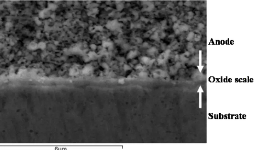
The fabrication technology being developed involved a firing stage at elevated temperatures, therefore, the stainless steel intrinsically formed a chromium-based oxide layer (oxide scale) on its surface. In order to examine the potential influence of a formed oxide scale on cell performance, microanalysis was carried out on a cross-section of a bi-layer processed in a same manner except that the firing temperature was increased to 1100 °C. An oxide scale thermally grown on a metal substrate underneath an anode layer is shown in Figure 4. The oxide scale was found to be about 1 µm in thickness. An EDS analysis confirmed that the oxide scale was rich in chromium. Assuming that the oxide scale was made of pure Cr2O3, from conductivity data for Cr2O3 (4), the area specific
resistance of the oxide scale at a fuel cell operating temperature in the range of 600 to 650 °C was estimated to be less than 0.003 Ωcm2, which was nearly two order of magnitude lower than any other resistive components; e.g., 0.1 Ωcm2 for typical electrolyte layers. Accordingly, an oxide scale grown on the metal substrate during a firing stage was expected to have no deleterious impact to the cell performance.
Figure 4. A cross-sectional SEM micrograph of an interface between an anode and a metal substrate processed at 1100 °C, showing a thermally grown oxide scale in between. Characterization of a ceria cell at intermediate temperatures
Fabricated ceria cells described above were unsymmetrical, having cathodes smaller than anodes in area; current density was defined by the area of cathode (0.29 cm2). Current-voltage (I-V) and current-power (I-P) characteristics of a ceria cell tested using humidified 50 % hydrogen in argon and air at temperatures of 650 and 600 °C are shown in Figure 5. Open circuit voltage showed relatively lower values, below 0.75 V, while terminal voltage decreased almost linearly with current density, and the cell was found to deliver higher current densities, over 1 A/cm2, and achieved a maximum power density of over 450 mW/cm2 at 650 °C.
The impedance spectrum under open circuit voltage at 650 °C is shown in Figure 6. The spectrum has one distorted arc over a frequency range of 1 kHz to 130 mHz having two intercepts at 0.13 Ωcm2 and 0.35 Ωcm2. The total resistance of 0.35 Ωcm2 on the impedance measurement was almost in agreement with the total resistance (0.3 Ωcm2) calculated from the slope of the i-v curve in Figure 5. It was thought that the difference of 0.22 Ωcm2 in intercept corresponded to polarization for electrodes, cathode and anode.
0 0.2 0.4 0.6 0.8 1 0 500 1000 1500 2000 0 100 200 300 400 500 600
Current density (mA/cm2)
T erm in al vol ta ge (V) Po wer d ensi ty (mW /cm 2) 0 0.2 0.4 0.6 0.8 1 0 500 1000 1500 2000 0 100 200 300 400 500 600
Current density (mA/cm2)
T erm in al vol ta ge (V) Po wer d ensi ty (mW /cm 2)
Figure 5. I-V and I-P characteristics of a ceria cell tested using humidified 50% hydrogen in argon and air at 650 °C (circle symbols) and 600 °C (square symbols), respectively. According to our separate work on La0.6Sr0.4Co0.2Fe0.8O3 perovskite (5), the area specific
resistance for La0.6Sr0.4Co0.2Fe0.8O3 was estimated to be about 0.27 Ωcm2 at 650 °C,
which was comparable to the polarization resistance on the impedance measurement. It was therefore found that the cathode accounted for most of the polarization resistance and that the anode polarization was less influential to the ceria cell tested. It should be noted that although the anode was exposed to an oxidizing atmosphere during the firing stage for cathode, the anode functioned without any pre-treatment; the anode was reduced
in-situ at the operating temperature.
Although the usage of ferritic stainless steels at the intermediate temperature of 650 °C raised concerns regarding the long term stability of the metal support affected by the formation of a brittle sigma phase, the series of processing technologies developed were found to be feasible for fabrication of metal-supported ceria cells that could be operated at an intermediate temperature.
-0.1 0 0.1 0.2 0.3 0 0.1 0.2 0.3 0.4 Z’ (Ω cm2) -Z ” ( Ω cm 2) 1 kHz 130 mHz 63 Hz -0.1 0 0.1 0.2 0.3 0 0.1 0.2 0.3 0.4 Z’ (Ω cm2) -Z ” ( Ω cm 2) 1 kHz 130 mHz 63 Hz
Summary
In order to evaluate the feasibility of using wet processing technologies involving spraying of colloidal ceramic suspensions and sintering stages for the fabrication of metal-supported cells at lower costs, a tri-layer comprising a lanthanum strontium cobalt iron perovskite cathode, a doped ceria electrolyte and a nickel ceria cermet anode was fabricated on a porous stainless steel substrate, and was tested with humidified 50 % hydrogen in argon supplied to the anode and air supplied to cathode at intermediate temperatures of 650 and 600 °C. Open circuit voltage showed relatively lower values, below 0.75 V, however the cell was found to deliver higher current densities, over 1 A/cm2, and achieved a maximum power density of over 450 mW/cm2 at 650 °C. It was found that the cathode accounted for most of the polarization resistance and that the anode polarization was less influential to the ceria cell tested.
Acknowledgments
The authors are grateful to Dr. Suwas Nikumb, IMTI-NRCC, for the laser-machining of metal disks. The authors acknowledge the technical assistances of Mr. Jim Margeson, IRC-NRCC, for SEM&EDS analysis, and of Mr. Nguon Lim, ICPET-NRCC, for X-ray diffraction analysis. This work was supported by National Research Council Fuel Cell and Hydrogen Program under National Research Council of Canada.
References
1. K. Wippermann, U. Stimming, H. Jansen and D. Stover, in SOFC-III, S. C. Singhal and H. Iwahara Editors, PV 93-4, p.180, The Electrochemical Society Proceedings Series, Pennington, NJ, (1993).
2. N. Oishi, Y. Yoo and I. Davidson, in the 7th European SOFC Forum conference CD, U. Bossel Editor, P0423, European Fuel Cell Forum, Oberrohrdorf,
Switzerland, (2006).
3. C. Kleinlogel and L. J. Gauckler, in SOFC-VI, S. C. Singhal and M. Dokiya Editors, PV 99-19, p.225, The Electrochemical Society Proceedings Series, Pennington, NJ, (1999).
4. A. Holt and Per Kofstad, Solid State Ionics, 100, 201 (1997).
5. N. Oishi, Y. Yoo and I. Davidson, in SOFC-IV, S. C. Singhal and J. Mizusaki Editors, PV 2005-07, p.1645, The Electrochemical Society Proceedings Series, Pennington, NJ, (2005).