Publisher’s version / Version de l'éditeur:
Photochemistry, pp. 191-210, 2011
READ THESE TERMS AND CONDITIONS CAREFULLY BEFORE USING THIS WEBSITE.
https://nrc-publications.canada.ca/eng/copyright
Vous avez des questions? Nous pouvons vous aider. Pour communiquer directement avec un auteur, consultez la
première page de la revue dans laquelle son article a été publié afin de trouver ses coordonnées. Si vous n’arrivez pas à les repérer, communiquez avec nous à [email protected].
Questions? Contact the NRC Publications Archive team at
[email protected]. If you wish to email the authors directly, please see the first page of the publication for their contact information.
Archives des publications du CNRC
For the publisher’s version, please access the DOI link below./ Pour consulter la version de l’éditeur, utilisez le lien DOI ci-dessous.
https://doi.org/10.1039/9781849732826-00191
Access and use of this website and the material on it are subject to the Terms and Conditions set forth at
Fluorescence imaging on the nanoscale : bioimaging using near-field
scanning optical microscopy
Johnston, Linda J.
https://publications-cnrc.canada.ca/fra/droits
L’accès à ce site Web et l’utilisation de son contenu sont assujettis aux conditions présentées dans le site LISEZ CES CONDITIONS ATTENTIVEMENT AVANT D’UTILISER CE SITE WEB.
NRC Publications Record / Notice d'Archives des publications de CNRC:
https://nrc-publications.canada.ca/eng/view/object/?id=5e934d5c-d5e1-415d-a3df-13f457d2c234
https://publications-cnrc.canada.ca/fra/voir/objet/?id=5e934d5c-d5e1-415d-a3df-13f457d2c234
3 Fluorescence Imaging on the Nanoscale:
Bioimaging Using Near-field Scanning Optical
Microscopy
Linda J. Johnston
DOI: 10.1039/b000000x [DO NOT ALTER/DELETE THIS TEXT]
5
Fluorescence microscopy is one of the most widely used tools for
visualization of biological structures, despite the fact that diffraction of
light limits the spatial resolution to several hundred nanometers for visible
excitation. This review will focus on one method for overcoming the
diffraction limit and achieving nanoscale spatial resolution in optical
10microscopy, namely near-field scanning optical microscopy. A brief
overview of the technical details of various aperture and apertureless-based
near field methods is presented, followed by examples that illustrate recent
applications of near field techniques to cellular imaging. Finally,
presepctives on new approaches and a comparison with recent
15developments in super-resolution fluorescence imaging are presented.
1 Introduction
Fluorescence microscopy has been widely used to visualize biological structures. It has a number of advantages, including the availability of a wide range of fluorescent probes with environment-sensitive properties, high sensitivity (down to the level of
20
single molecules), high temporal resolution, straightforward implementation and low cost. Furthermore, the development of genetically encodable fluorescent proteins has greatly enhanced the possibilities for live cell fluorescence imaging. Nevertheless, diffraction restricts the maximum spatial resolution of optical microscopy to approximately half the wavelength of the excitation light, a very significant
25
limitation for visualizing proteins and complexes, which are typically less than 10 nm in size, in the densely packed cellular environment. There have been many improvements since the first optical microscope designs over 400 years ago, including the use of a confocal geometry to reduce out-of-focus background and two-photon and total internal reflection methods to improve axial resolution;
30
however, none has overcome the basic limitation imposed by diffraction of light. Alternative approaches such as scanning probe microscopy and electron microscopy do provide capabilities for high spatial resolution imaging, achieving molecular and even atomic scale resolution in some cases. However, they have significant issues with lack of chemical specificity (eg, with atomic force microscopy), harsh sample
35
preparation requirements (eg, for electron microscopy) and incompatibility with imaging live cells. The last two decades have seen a revolution in optical microscopy with the development and application of two conceptually different strategies for achieving nanoscale spatial resolution.1
The first of the approaches to overcome the fundamental limitation of diffraction
40
of light was a family of near-field optical techniques that either utilize aperture-based probes to illuminate the sample or rely on the enhanced optical field in proximity to a sharp metallic tip to locally excite the sample.2-4 More recently the
development of far-field super-resolution methods based on the principle of switching fluorophores on and off sequentially in time has provided an alternative
45
means of resolving subcellular structures.5These include several ensemble methods
based on targeted switching and readout; molecules are switched between on and off states (usually a fluorescent singlet state and a dark ground state) using a high intensity shaped laser beam to deplete “on” molecules at the edges of a diffraction limited excitation area. The first implementation, stimulated emission depletion
50
microscopy (STED), uses one laser beam to excite fluorescence and a second doughnut-shaped high intensity beam at longer wavelength to stimulate emission from fluorophores at the edges of the excited region, thereby creating a sub-diffraction spot size.6A second stochastic approach for achieving super-resolution
is based on randomly switching on a low density of excited molecules such that
55
individual molecules are always separated by greater than the diffraction limit. Individual molecules are imaged, the centers of their diffraction-limited spots are localized with nanoscale precision and images are created by repeating the activation/measure/bleach sequence many times. The two most common variations of the stochastic switching and readout approach are photoactivation localization
60
microscopy (PALM) and stochastic optical reconstruction microscopy (STORM), which differ by the type of switchable probe used.2-4
This review covers recent progress in the application of near-field techniques to biological problems. The following section provides a brief overview of the near-field principle and the technical implementation of aperture-based near-near-field
65
scanning optical microscopy (NSOM). The interested reader is referred to a number of excellent reviews that provide considerably more detail on various technical aspects of the development of NSOM microscopes and probes.7-14 Later sections
discuss applications of near field methods for fluorescence imaging of biological samples, focusing primarily on results obtained since 2005. Much of the data
70
reported in earlier studies was of the “proof-of-principle” variety, demonstrating impressive resolution, but often lacking in new biological insight. This review will emphasize detailed studies that put near-field imaging of biological samples on a quantitative footing and that attempt to correlate nanoscale organization with biological function. Recent advances in apertureless NSOM and combinations of
75
NSOM with other methods are also presented, prior to concluding with a perspective on future directions and a comparison with super-resolution techniques.
2 Near-field Approaches to Overcome the Diffraction Limit
Diffraction limits the size of the spot to which light can be focused using conventional lenses. According to Abbe’s theory of diffraction and the Rayleigh
80
criterion,15two objects can be resolved when their separation, d, is greater than:
d = O.61 /n sin
where = wavelength and n sin is the numerical aperture, NA, of the focusing lens (n = refractive index of the medium, = the angle of acceptance of the lens). When light is focused using a lens and the transmitted or emitted light is collected
85
and imaged on a detector, only the far-field propagating component is collected because both the collection lens and detector are in the far-field (ie, at distances greater than many times the wavelength of the light). The non-propagating evanescent component that exists near the object at dimensions less than the
wavelength of light is not typically collected by the lens, hence the origin of Abbe’s
90
diffraction limit. Use of high numerical aperture objectives (NA> 1) leads to the general approximation that the lateral spatial resolution is limited to ~/2 or 200-300 nm for visible light in the best case scenario with optimal optical components and good signal-to-noise. Although in principle one can improve resolution by going to shorter wavelength, this is not a practical solution for fluorescence microscopy.
95
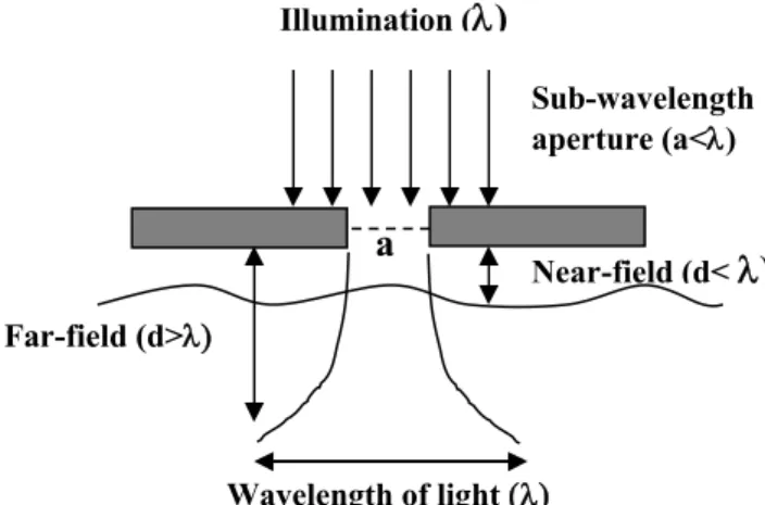
The basic concept of using near-field optics to overcome the diffraction limit was originally developed by Synge over 80 years ago (Fig. 1).16He hypothesized that it
was possible to deliver light through apertures with dimensions smaller than the wavelength of light. If the aperture was placed in close proximity to the sample (ie, in the near-field), then the light passing through the aperture could be used to image
100
a specimen without diffraction degrading the resolution. Although the concept was relatively simple, significant advances in methods for fabricating nanometer-sized apertures and controlling the aperture-sample distance were necessary before the concept could be implemented. The first proof-of-principle experiments at optical wavelengths were reported simultaneously by two groups in 1984,17, 18leading to the
105
development of a family of NSOM methods.
Fig. 1. Basic principle of near-field illumination. Light passes through an aperture,
a, with dimensions that are smaller than the wavelength () of the incident light. The spatial resolution is determined by the aperture dimensions in the x-y plane and by the decay of the evanescent field in the z-dimension.
110
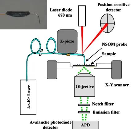
The most common method for implementing NSOM utilizes an optical fiber probe with a sub-wavelength aperture to illuminate the sample (Fig. 2). The probe is positioned close to the sample (within the near-field) and either fluorescence or transmitted light is collected using a high NA objective mounted underneath the
115
sample. Images are obtained by raster-scanning the sample under the tip, giving simultaneous topographic and optical scans. One possible microscope configuration is shown in Fig. 3. A continuous laser beam is coupled into the optical fiber probe which is mounted in an AFM piezo scanner equipped with a position sensitive detector to regulate the tip-sample interaction. The probe and scanner are mounted
120
on an x-y scanning stage supported on an inverted optical microscope. This has the advantage of allowing brightfield or epifluorescence measurements in order to locate specific areas of the sample prior to high resolution NSOM imaging. NSOM is also
Sub-wavelength
aperture (a<
)
Wavelength of light
Illumination (
)
Near-field (d<
)
Far-field (d>
a
Fig. 2. Schematic representation of the various approaches for near field scanning
125
optical microscopy: A, aperture-based NSOM; B, tip-enhanced (apertureless) NSOM; c, Tip-on-aperture NSOM.
Fig. 3. Schematic of a near field fluorescence microscope based on an inverted
130
optical microscope and using a cantilevered probe mounted on the z-scanner of an atomic force microscope. A bent NSOM probe is shown at top left.
frequently implemented on a laser scanning confocal microscope.
Although most applications for biological samples have employed an illumination
135
geometry similar to that shown in Fig. 3, an alternate configuration employs sample irradiation through an objective and signal collection by an NSOM probe positioned
Position sensitive detector X-Y scanner Laser diode 670 nm Emission filter Z-piezo NSOM probe Sample A r-K r L as er APD Avalanche photodiode detector Notch filter Objective Position sensitive detector X-Y scanner Laser diode 670 nm Emission filter Z-piezo NSOM probe Sample A r-K r L as er APD Avalanche photodiode detector Notch filter Objective Position sensitive detector X-Y scanner Laser diode 670 nm Emission filter Z-piezo NSOM probe Sample A r-K r L as er APD Avalanche photodiode detector Notch filter Objective
A B C
A B C
500 nm
1 m
within the optical near-field. NSOM can also be configured in a reflection mode for non-transparent samples. In this case the probe may be used to both deliver and collect light from the sample. Alternately, the tip is used to illuminate the sample
140
and collection optics are mounted to the side of the probe.
The two most important components of a near-field microscope are the probe and the system used to regulate the tip-sample distance; collectively they determine the attainable resolution and the ability to control the force exerted on the sample and to minimize damage to the sample. Various approaches have been used and the details
145
are summarized in earlier reviews.9, 19 The first successful version of an NSOM
probe was based on a tapered single mode optical fiber created by a laser heating and pulling method and then coated with aluminum.20 Probes must be coated with
metal, usually aluminum, to confine the light within the probe in regions where the probe dimensions are smaller than the wavelength of the light. Although metal
150
coating is typically accomplished by vacuum evaporation using a shadow coating method to create an aperture, more recent approaches using focused ion beam milling give better-defined and more reproducible apertures. Chemical etching methods provide an alternate route to probe fabrication and can be used to create probes with a large cone angle, rather than the long tapered probe produced by laser
155
heating/pulling.21,22 The shorter tapered region leads to increased light throughput.
The transmission efficiency of NSOM probes decreases rapidly as the probe aperture decreases, which sets a practical limit of approximately 50 nm for the spatial resolution with an aperture based approach.
Two main methods have been used to regulate the tip-sample distance.9, 19The
160
first uses straight optical fiber probes with a shear-force feedback system based on either an optical or a tuning fork method. Alternately, bent cantilevered probes can be used in a regular tapping mode AFM operation (Fig. 3). The pros and cons of each method have been summarized.9Fig. 4 shows a bent optical fiber probe created
by a two-step chemical etching method and with a focused ion beam milled aperture.
165
Probes of this design have been reported to have transmission efficiencies that are between 10 to 40 times higher than those for tapered optical fiber probes, and are compatible with cellular imaging and imaging in an aqueous environment.22-24 A
typical image of a polymer sphere test sample is also presented in Fig. 4
170
Fig. 4. A scanning electron microscopy image of an aluminum-coated probe with an
aperture (~ 90 nm in diameter) produced by focused ion beam milling (left). NSOM fluorescence image of 40-nm dye-loaded polymer spheres embedded in a thin polymer film and imaged with a 60-nm aperture probe (right).
3 Cellular Imaging with Aperture-based NSOM
The quest for nanoscale fluorescence imaging of biological samples has been motivated by the inability of conventional fluorescence microscopy to resolve sub-cellular structures. Since NSOM is inherently a surface-sensitive technique, applications have typically been directed towards understanding the organization or
180
compartmentalization of cellular membranes. The classical fluid mosaic view25 of
the cell plasma membrane as a sea of lipids with freely diffusing proteins has now been replaced by a model in which the lateral organization of membrane receptors is domains plays a critical role in controlling protein-protein interactions and the assembly of signaling complexes.26-29 This compartmentalization of cellular
185
membranes provides an important element of spatial and temporal control of cell signaling and can also modulate the interaction of the cell with its environment, as for example in invasion of viruses and bacteria. Frequently the localization of proteins in specific membrane domains is at least partly controlled by the lipid environment. In particular, cholesterol and sphingolipid-enriched domains known as
190
lipid or membrane rafts have been shown to sequester specific classes of proteins.27
Estimates of the size of lipid rafts are typically less than 200 nm and their small size and dynamic nature make their direct detection, especially in live cells, a significant challenge.30NSOM and other super-resolution techniques are an obvious solution to
this problem.
195
The cellular imaging examples presented in this section all deal with a common theme of assessing the distribution of membrane receptors and domains and elucidating their impact on biological function. Although there are a few reports of live cell imaging using NSOM,31-34most detailed studies have examined fixed cells,
either dry or in physiological buffer, generally using immunofluorescence labeling
200
with specific antibodies to detect the protein or membrane domain of interest.
Membrane receptors and signaling complexes
One of the first applications of NSOM for visualization of signaling complexes examined-adrenergic receptors (AR), a widely-studied member of the G-protein coupled receptor family, an important class of therapeutic targets. Functional AR
205
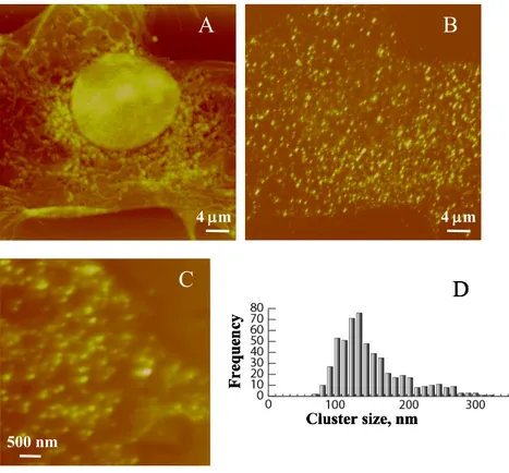
receptors were shown to be organized in clusters of ~140 nm average diameter with a cluster density of ~ 1/m2in both immortalized H9C2 cells and primary murine
cardiomyocytes, Fig. 5. Quantification of the cluster intensities was combined with a calibration based on the average fluorescence intensity of the antibody used to label the receptor and assumptions on labeling stoichiometry to estimate that the packing
210
density of proteins varied from 12-72 for cluster diameters of 120-160 nm. Two-color experiments demonstrated that approximately 20% of clusters are colocalized with caveolae membrane domains. Adrenergic stimulation with the ligand isoproterenol produced no change in either cluster size or intensity, indicating that the receptor is pre-associated in nanoscale signaling islands. The preorganization of
215
the receptor provides a mechanism for rapid response to AR agonists without the
requirement for large scale diffusion to form signaling complexes. The ability to monitor organization of signaling complexes on a length scale that bridges the gap between confocal microscopy and the nearest-neighbour interactions probed by fluorescence resonance energy transfer illustrates the potential of NSOM to
220
determine the stoichiometry of various proteins within signaling domains and provides new insight on how GPCRS produce cellular responses.35, 36
Fig. 5. NSOM imaging of 2AR in fixed murine neonatal cardiac myocytes and
H9C2 cells. (A, B) Simultaneously recorded NSOM topography and fluorescence
225
images from neonatal myocytes. (C) A small scale fluorescence image for AR in
H9C2 cells. (D) Histogram showing the distribution of cluster sizes for the receptor in unstimulated H9C2 cells. Reproduced from Nat. Chem. Biol. 2005, 1, 196, with permission of Macmillan Publishers Ltd.
230
Although the initial study of AR provided significant insight, the quantification
of the receptor based on fluorescence intensities from immunofluorescence staining has some limitations. These include the requirement for assumptions concerning the stoichiometry of antibody labeling and the possibility that the large size of the labeling primary-secondary antibody complex leads to an underestimate of the
235
number of receptors/cluster. These constraints have been addressed by expressing a fluorescent protein fusion (Venus-AR) in HEK293 cells at variable expression
levels.37 The results showed that the number of small nanometer-sized clusters
increased by a factor of ~3 with increased Venus-AR expression level, but that
their size was roughly constant with an average diameter of ~150 nm and with a
240
range of 2 to ~60 proteins/cluster. The constant cluster size independent of expression level may reflect a biological preference for localization of the receptor in nanoscale domains. The cluster size, density and number of AR/cluster are
similar to those for AR clusters in H9C2 and primary cardiomyocytes. This
suggests that the inducible expression of AR is representative of the normal
245
physiological distribution of the receptor and that there is a biological preference for
4
m
4
m
A
B
500 nm
C
Cluster size, nm
F
re
qu
en
cy
D
4
m
4
m
A
B
500 nm
C
500 nm
C
Cluster size, nm
F
re
qu
en
cy
D
Cluster size, nm
F
re
qu
en
cy
D
AR distribution in small nanometer-sized clusters.
A second detailed quantitative study of membrane protein clustering visualized the distribution of a C-type lectin, DC-SIGN, that is involved in pathogen recognition for several viruses and other microorganisms.38 DC-SIGN is expressed
250
in dendritic cells that help to regulate immune responses and its spatial arrangement in the membrane is believed to be linked to its function as a viral receptor. NSOM studies established that >80% of the receptor was localized in nanodomains with a mean size of 185 nm and that the domains were randomly distributed across the membrane surface. Calibrations using the average intensity of single molecules
255
indicated that there was an average of 5-10 proteins/cluster, but that the packing density was very heterogeneous (ie, the intensity did not scale linearly with cluster size as would be expected for a single packing density in both large and small clusters). An earlier study of the same receptor in fixed cells in an aqueous environment gave similar conclusions, although there were some differences in
260
cluster size and protein density.39 Finally, single molecule bleaching studies
demonstrated that NSOM could be used to image individual proteins within a cluster at much higher density than is possible with confocal microscopy. The presence of DC-SIGN in domains with sizes that are similar to viruses and the heterogeneity of domain packing densities were hypothesized to be important factors for providing
265
flexibility for receptor binding to a variety of different pathogens.
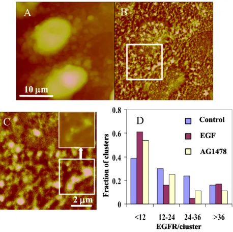
A third study from our group has probed the membrane distribution of the epidermal growth factor receptor, which is over-expressed in many solid tumors and thus an important therapeutic target.40 The EGFR is organized in small clusters with
an average size of 150 nm in both unstimulated and EGF-treated Hela cells, although
270
the distribution of cluster sizes is slightly wider after EGF treatment, Fig. 6. The packing densities vary substantially from cluster to cluster, with anywhere from 1 or 2 proteins to greater than 100 proteins/cluster and with the peak of the intensity histograms typically having 5-15 molecules/cluster. The relatively modest changes in cluster size and density after EGF stimulation suggest that receptors are
pre-275
organized in nanoscale domains on the cell surface, indicating that mechanisms for organization of the EGFR are independent of ligand activation on the length scale of 100 nm. Treatment with the tyrosine phosphorylation inhibitor, AG1478, led to a two-fold increase in cluster density and to a larger fraction of clusters with smaller diameters and fewer receptors. AG1478 also resulted in localization of small
280
individual clusters in larger, but non-contiguous, membrane patches, illustrating the hierarchial arrangement of protein domains on the cell surface. Two-color colocalization experiments demonstrated that the fraction of EGFR that colocalizes with both lipid rafts and caveolae decreased in the presence of the inhibitor. Overall, this study demonstrates the utility of high resolution fluorescence imaging for
285
understanding receptor clustering as a function of agonist and antagonist treatment, information that is relevant to design of therapeutic strategies based on modulation of EGFR signaling.
The organization of subunits of interleukin 2 (IL2) and interleukin 15 (IL15) cytokine receptors has been examined.41These receptors are both involved in
T-cell-290
mediated immunity and, although they share receptor subunits and have common cellular responses, they can also exhibit distinct and contrasting contributions to immunity. NSOM studies of the IL2 and IL15 -subunits in a human leukemia T-cell line indicated that there were two different populations for both receptors, one comprised of relatively large clusters and one with either individual proteins or very
Fig. 6. NSOM imaging of EGFR in fixed HeLa cells. (A, B) Simultaneously
recorded NSOM topography and fluorescence images. (C) A small scale fluorescence image for the boxed area in image B. The inset at the top right shows the region outlined at the bottom right on a different intensity scale, illustrating that some brighter regions correspond to multiple small clusters. (D) Bar chart shows the
300
variation in the number of EGFR/cluster for control, EGF-stimulated and AG1478-treated cells. Reproduced from J. Biol. Chem. 2010, 285, 3145, with permission of the American Society for Biochemistry and Molecular Biology Inc.
small clusters. Quantitative size and intensity analysis demonstrated that the
305
monomer fraction was ~30% for IL15 but much lower for IL2. Interestingly, correlation of cluster size with intensity for each receptor indicated that there was a constant packing density for each receptor, but that the packing density for IL2 was approximately 10 times that of IL15, even though their average cluster diameters were quite similar (450 nm and 360 nm). This result provides evidence that domains
310
may be assembled from “building blocks with repeated structures and composition”,
41 in contrast to various other studies (see above) which found a wide range of
packing densities for individual clusters of membrane proteins. There was also a significant degree of overlap of the two receptors based on an estimate of 40% colocalization. Previous FRET data for IL2 and IL15 had shown the presence of a
315
significant fraction of dimeric or oligomeric receptor. Further experiments combining NSOM with FRET would be required to elucidate the relationship
10
m
A
B
2
m
C
F
ra
ct
io
n
of
c
lu
st
er
s
EGFR/cluster
0
0.2
0.4
0.6
0.8
<12
12-24 24-36
>36
Control
EGF
AG1478
EGFR/cluster
D
10
m
A
B
10
m
10
m
A
B
2
m
C
2
m
2
m
C
F
ra
ct
io
n
of
c
lu
st
er
s
EGFR/cluster
0
0.2
0.4
0.6
0.8
<12
12-24 24-36
>36
Control
EGF
AG1478
EGFR/cluster
F
ra
ct
io
n
of
c
lu
st
er
s
EGFR/cluster
0
0.2
0.4
0.6
0.8
<12
12-24 24-36
>36
Control
EGF
AG1478
F
ra
ct
io
n
of
c
lu
st
er
s
EGFR/cluster
0
0.2
0.4
0.6
0.8
<12
12-24 24-36
>36
Control
EGF
AG1478
Control
EGF
AG1478
EGFR/cluster
D
between dimers/oligomers and the two populations of receptor and the constant cluster packing density observed by NSOM.
Two recent reports from the Chen group have used NSOM plus
320
immunofluorescence with quantum dot labeling to examine the membrane distribution of various receptors on the surface of T-cells.42, 43 In one case they
demonstrated that only 10% of the T-cell receptor (TCR) clusters were >90 nm in diameter, whereas 40% of -TCR clusters were larger than 90 nm.42 Significant
changes in cluster size for V2V2 T cells were observed following antigen-induced
325
in vivo clonal expansion of the cells. The clustering behavior of the TCR was maintained but in addition to nanoclusters (<250 nm), larger features assigned as nanodomains (> 250 nm) and microdomains (>1000 nm) were also observed. A second study showed that TCRs (CD3, CD4 and CD8) were found as either isolated receptors or small nanoclusters labeled with 2-4 quantum dots in unstimulated T
330
cells with relatively low levels of colocalization (<10% of CD3 with either CD4 or CD8).43Activation of the cells led to significant changes in the distribution of the
receptors with co-clustering of CD3 with CD4 or CD8 to give 200-500 nm nanodomains and >500 nm microdomains. In these studies the brightness and resistance to photobleaching of quantum dots provided an advantage over standard
335
immunofluorescence with dye-labeled antibodies.
Visualizing membrane rafts
A large number of studies have used glycolipid or glycosylphosphatidylinositol (GPI)-linked proteins as markers for raft domains and the same approach has been used for super-resolution studies. In one example, Chen and coworkers have taken
340
advantage of NSOM’s capability to record topography and fluorescence to show that two different glycolipids, gangliosides GM1 and GM3, are localized in distinct, non-overlapping clusters on the plasma membrane of polarized MDCK cells.44
Furthermore, the GM3 raft domains (mean size of 190 nm) were distributed predominantly on the microvilli-like protusions of the apical cell membrane whereas
345
the GM1 nanodomains (mean size of 160 nm) were found on the edge of or between the microvilli. The same group has also examined the effects of temperature and fixation on the nanoscale distribution of two raft markers, GM1 and the protein CD59, in the membrane of T-cells.45 Lower temperatures (4oC) resulted in the
redistribution of raft clusters as well as their enlargement by a factor of 30-60% and
350
a greater degree of colocalization of the two raft markers. The results also showed that raft markers were distributed at raised regions of the cell membrane. The changes in distribution of raft markers as a function of temperature are directly relevant to the widely-used approach of using detergent extraction at low temperature as a means to quantify the extent of liquid-ordered “raft” phases in cell
355
membranes.46
Similar clustering of asialo-GM1 was observed in HeLa cells, using antibody labeling to detect the glycolipid clusters.47 Two populations of asialo-GM1 were
observed, one that was clustered in domains with an average size of ~90 nm and a second diffuse level of glycolipid. Detergent extraction studies showed that
asialo-360
GM1 was present in both soluble and insoluble membrane fractions leading to the hypothesis that the membrane insoluble fraction corresponded to the clustered glycolipid observed in the NSOM images. Colocalization studies showed that a fraction of the asialo-GM1 colocalized with caveolae, which are specialized domains with an invaginated membrane structure and a lipid composition similar to rafts. The
limited spatial resolution available with confocal microscopy gave apparent colocalization values that were over twice those obtained by NSOM, indicating the limitations of confocal for assessing overlap of small membrane domains.
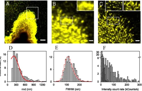
A more detailed study of the distribution of GM1 has been published very recently.48Labeling GM1 with its fluorescent protein receptor, CtxB, in monocytes
370
demonstrated the formation of densely packed clusters with a distribution of sizes (peaking at 123 nm) and numbers of protein-GM1 complexes (Fig. 7); clustering was significantly disrupted by MCD treatment, although some heterogeneity was still observable, Fig. 7. Dendritic cells that express ~30 times less GM1 also showed clusters, typically with ~2 CtxB/cluster. Two-color NSOM studies showed that
375
GM1-CtxB domains had low colocalization with both raft and non-raft proteins. However, the GM1 clusters were shown to be in close proximity to cluster of both LFA-1 and CD55, both of which are believed to localize in rafts, but to be randomly distributed with respect to the non-raft protein, CD71. The high resolution imaging results were combined with computational studies, leading to the conclusion that
380
small nanoscale rafts must be interconnected in the plasma membrane. It was further hypothesized that this interconnectivity is a necessary prerequisite for larger scale coalescence upon cell activation.
385
Fig. 7. (A) Confocal image of CtxB-GM1 at the cell surface of a fixed monocyte.
Scale bar: 5 μm. (B, C) Confocal zoom-in and NSOM images of the area highlighted in A. Scale bars: 1 μm. Insets in B and C highlight the increase in resolution afforded by NSOM. (D) Histogram of the nearest neighbour distribution (nnd) of
390
CtxB-GM1 spots (bars) and simulations of random organization (line). (E) Size distribution of individual CtxB-GM1 spots (bars) and of individual CtxB on the glass (line) obtained with the same NSOM probe. (F) Intensity distribution of CtxB-GM1 for multiple cells (gray) and of single CtxB nonspecifically attached to glass (dash). Reproduced from Proc. Natl. Acad. Sci. 2010, 107, 15437, with permission
395
of National Academy of Sciences.
Garcia-Parajo and coworkers have examined the distribution of the leukocyte-specific integrin, LFA-1, which mediates cell migration and cell adhesion and is involved in the formation of the immunological synapse.49 This study aimed at
addressing the role of lipid rafts in controlling integrin-mediated cell adhesion.
400
Earlier confocal studies had demonstrated that LFA-1 colocalized with the glycolipid GM1 and that raft disruption interfered with ligand binding. Interestingly, the higher spatial resolution available with NSOM demonstrated that LFA-1 localized in small clusters (size <85 nm, limited by probe aperture size) but did not colocalize with GPI-AP, a raft marker. The latter showed a large population of
405
monomers (70%) but also a small population of nanodomains (30%, 2-4 proteins/nanocluster) that were clustered in specific regions. Despite the absence of colocalization, it was observed that about half of the GPI-PA clusters were in close proximity to LFA-1 clusters in the absence of ligand activation, suggesting the formation of ligand-independent platforms. Ligand activation (with ICAM)
410
increased the number of GPI-AP clusters to 80%, resulting in the formation of localized adhesion platforms with ICAM-LFA-1 clusters. These results led the authors to conclude that the formation of distinct but proximal nanodomains (or hotspots) of the two protein receptors occurs in the absence of ligand, probably as the result of interactions with the cytoskeleton. Ligand binding to the integrin
415
receptor leads to larger functional platforms that promote adhesion. It should be noted that the use of two-color experiments, quantitative analysis of cluster size and intensity, and the presence of corroborating data from EM were all necessary in order to develop a complete picture of the compartmentalization of LFA-1. Furthermore, the compartmentalization is more complex than that observed at lower
420
spatial resolution using confocal microscopy.
A common theme emerging from these studies is the formation of nanoscale membrane raft domains as assessed by labeling the commonly-employed glycolipid and protein raft markers. Although the NSOM studies are for fixed cells, another recent study has provided evidence for nanoscale lipid domains in live cells.50
425
Interestingly, previous NSOM studies have also detected small nanoscale glycolipid clusters in supported lipid membranes.51, 52
4 Antennas and Apertureless
The above examples highlight the utility of NSOM imaging with aperture probes for probing the nanoscale organization of membrane proteins and lipid domains in
430
cellular membranes. Despite these advances, the reproducible fabrication of probes remains a significant challenge, with most groups making their own custom probes. Furthermore, the available resolution is limited by the light transmission through the optical fiber probe to ~50 nm; in fact, most published studies have used probes with aperture diameters between 70-90 nm. Several apertureless and optical
antenna-435
based approaches have been developed in attempts to improve the spatial resolution. Apertureless (ortip-enhanced) near-field approaches rely on the local enhancement of illuminated or scattered light in a small region adjacent to the end of a sharp metal or metal-coated tip (Fig. 2).53-55Several effects contribute to the field
enhancement, including excitation of surface plasmon resonances in the metal, an
440
electrostatic lightning-rod effect associated with localized surface charge densities and antenna resonances.53, 55Pointed metal tips are also referred to as antennas based
methods have been used successfully in a range of applications with signal enhancements of more than 10 orders of magnitude having been reported.55
445
However, tip-enhanced techniques for fluorescence microscopy are somewhat more complex. This arises primarily because the tip-induced fluorescence enhancement depends on several factors, including the tip material and shape, the polarity and wavelength of the illuminating light used, the tip-sample distance and reduction of the fluorophore lifetime/intensity by proximity to the metal tip. Early
450
demonstrations of apertureless methods focused on single isolated molecules. For example, <10-nm resolution was demonstrated for imaging individual dye-labeled DNA molecules using a silicon tip.56 A number of other examples have reported
impressive spatial resolution for imaging single dye molecules or quantum dots deposited on glass substrates and for imaging carbon nanotubes, frequently using an
455
antenna approach with a small metal nanoparticle attached to the end of the tip.55, 57
In one particularly interesting study, Sandoghdar and coworkers examined the effects of the gold nanoparticle diameter and the tip-sample distance on the achievable spatial resolution and fluorescence enhancement using a combination of computational work and imaging of dye molecules embedded in a thin film. These
460
results clearly demonstrated the trade-off between fluorescence enhancement and spatial resolution. Optimal signal to noise with 20-nm resolution and an enhancement factor of 30 times was achieved with an 80-nm diameter nanoparticle.
Although the development of high spatial resolution is driven by the need for higher resolution biological imaging methods, most studies have not yet tackled
465
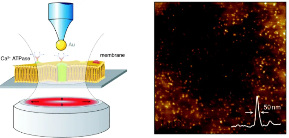
biological samples in a physiological environment. However, a recent example from the Novotny group has shown that Ca2+ATPases can be imaged in isolated
erythrocyte membrane patches in an aqueous environment using an 80-nm gold nanoparticle antenna (Fig. 8). This study demonstrated ~50 nm spatial resolution with a fluorescence enhancement of ~8 and the ability to resolve individual closely
470
spaced proteins.58
Fig. 8. Cartoon depicting the principle for antenna-based NSOM (left). NSOM
475
image showing individual Ca2+ATPase in the erythrocyte plasma membrane with a
cross section through one of the fluorescence spots indicating ~50-nm resolution. Reproduced from Nano Lett. 2008, 8, 642 with permission of the American
Chemical Society.
Apertureless approaches have demonstrated a significant improvement in spatial
480
resolution over aperture-based near field approaches and have the added advantage of avoiding the use of fragile-optical fiber based probes. However, they suffer from three significant restrictions that have so far prevented their wide-spread use, particularly for biological imaging. First, photobleaching is more problematic than in normal fluorescence microscopy, since the focused laser beam used to
485
continuously irradiate the tip also irradiates the sample. Second, the background signal that results from far-field irradiation of the tip is relatively high in some cases, and may exceed the tip-enhanced signal for samples with a high chromophore density. Finally, quenching of fluorophores by the metallic tip reduces the tip-enhanced signal, but does not affect the far-field background signal. A background
490
suppression method based on modulation of the feedback loop used to regulate tip-sample distance has been developed recently.59This method resulted in a ten-fold
improvement in fluorescence enhancement for measurements of a thin layer of relatively closely spaced dye molecules measured using an 80-nm gold nanoparticle antenna. Considerably larger improvements in the enhancement factor were obtained
495
when imaging an isolated membrane patch with a high density of calcium channels. One interesting observation was the wide variation in enhancement factors measured for individual molecules; this complication will preclude a quantitative intensity analysis of protein clusters, as has been successfully used with aperture-based NSOM (see above).
500
An elegant solution to the background and photobleaching issues associated with apertureless NSOM consists of placement of a metal tip in close proximity to a subwavelength aperture, Fig. 2.60, 61 In one example, the van Hulst group has
constructed a nanoantenna on the end of an aluminum-coated optical fiber probe with a 100-nm diameter aperture.62Excitation of the nanoantenna by the near-field
505
aperture results in lower background illumination of the sample than can be obtained with a focused laser beam and minimizes photobleaching. Initial studies on dye molecules embedded in a thin polymer film demonstrated 25-nm spatial resolution with low background and examined the effect of nanoantenna length on the antenna performance. The tip-on-aperture approach has recently been applied to cellular
510
imaging.12A resolution of 30 nm was demonstrated for imaging LFA-1 clusters on
the surface of monocytes; clusters measured with the antenna probe had an average size of 72+/-21 nm, whereas a conventional aperture NSOM probe was only able to set an approximate upper limit for the cluster size of 85 nm. The authors have argued that further optimization of the antenna geometry should result in improved
515
signal to background levels and higher spatial resolution. However, it remains to be seen whether this approach will be of general utility since the probe fabrication is complex and the method retains the problems associated with a bulky and fragile optical fiber probe.
5 Hybrid NSOM Methods
520Several recent studies have illustrated the potential of combining NSOM with dynamic measurements using fluorescence correlation spectroscopy (FCS). FCS relies on the temporal analysis of fluctuations of the fluorescence signal as fluorophores diffuse in and out of a small observation volume, and has been widely used to measure single molecule dynamics, yielding concentrations, diffusion
coefficients and association/dissociation constants for biomolecules.63 FCS is
usually implemented on a confocal microscope, with diffraction-limited optics resulting in femtoliter observation volumes. Reducing the size of the observation volume would provide several advantages, particularly for studies of membrane proteins. First, it would allow single molecule sensitivity even in the presence of
530
high molecular concentrations; confocal FCS measurements are typically limited to concentrations between 100 pM and 100 nM, whereas typical concentrations of biomolecules in cell membranes are in the M to mM range. Second, it would allow the detection of spatial heterogeneities in the dynamics of individual proteins or lipids confined to nanoscale membrane domains. Third, the shorter residence time of
535
molecules in the smaller observation volume would minimize photobleaching. These advantages have motivated a number of approaches for reduction of the observation volume for FCS measurements. The most successful to date has been the use of sub-wavelength sized apertures (zero-mode waveguides) in thin metal films which produce attoliter (10-18 l) and zeptoliter (10-21 l) observation volumes.64
540
Nanoapertures have significant promise for single molecule assays in solution and have also recently been employed to study diffusion in cell membranes.65, 66
However, their applicability is significantly limited by the requirements for growing cells on the metal films used to construct the apertures and for membrane invagination into the nanoapertures, which dramatically restricts the membrane area
545
that can be probed.
The use of near field optical probes with nanometer-sized apertures has the potential to allow both nanoscale imaging and dynamic measurements using FCS in reduced observation volumes/areas. An initial proof-of-principle experiment employed a sub-wavelength NSOM probe to measure diffusion of a dye-labeled
550
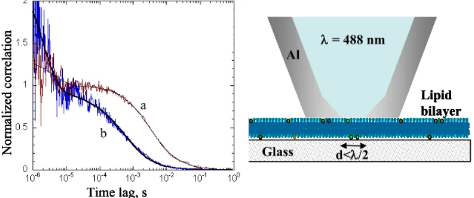
lipid in a supported lipid bilayer.67Using a probe with a 140-nm aperture diameter,
FCS-NSOM data indicated a roughly 10-fold reduction in diffusion time compared to confocal FCS, Fig. 9. The FCS-NSOM diffusion time combined with the measured diffusion coefficient for Oregon Green DHPE gave an excitation radius of 73 nm in excellent agreement with the probe aperture size, and clearly
555
demonstrating an order of magnitude reduction in observation volume for FCS-NSOM as compared to a confocal geometry. This study also demonstrated the need
Fig. 9. Cartoon (right) illustrating FCS-NSOM configuration for a supported lipid
bilayer. Correlation curves (left) showing the change in diffusion time for confocal (a) and NSOM (b) FCS measurements for Oregon Green–DHPE in a DOPC
560
membrane. Reproduced from Appl. Phys. Lett. 2008, 93, 163904 with permission of
Al = 488 nm Glass Lipid bilayer d</2 Time lag, s N or m al iz ed c or re la ti on a b Al = 488 nm Glass Lipid bilayer d</2 Al = 488 nm Glass Lipid bilayer d</2 Time lag, s N or m al iz ed c or re la ti on a b Time lag, s N or m al iz ed c or re la ti on a b
American Institute of Physics.
for further improvements to the probe design for more routine FCS measurements, particularly with smaller apertures.67-69A similar proof-of-principle experiment with
a larger NSOM probe (300 nm diameter aperture) gave data with superior signal to
565
noise for diffusion of fluorescent beads in solution.70
A combination of NSOM and FCS was used to image closely packed nuclear pore protein complexes and to measure diffusion of dye-labeled nuclear transport factor.71
This impressive experiment was possible by suspending isolated nuclear envelope membranes across 20 mm troughs in a regular grid so that pores in a free standing
570
membrane could be imaged with the NSOM probe and the probe positioned over an individual pore for FCS measurements of transport through the pore. A light-emitting triangular aperture was used as the near-field probe and the probe-sample distance was maintained using only the elastic response of the membrane, resulting in improved optical resolution over earlier studies using a fiber aperture probe and
575
force feedback to image a similar sample.72 The diffusion measurements for the
nuclear transport factor were consistent with interaction of the protein with amino acids on the edges of the channel during its transit through the pore.71Note that the
reduced observation volume is a significant advantage due to the high protein density in the nuclear pore envelope.
580
The first example of FCS-NSOM measurements on live cells was recently reported.34 This study used a 120-nm aperture probe to measure diffusion for two
different dye-labeled lipids in Chinese hamster ovary cells. A phosphatidylethanolamine probe gave results consistent with free diffusion, but with the diffusion time shifted to shorter times due to the reduced illumination area of the
585
NSOM probe. By contrast, sphingomyelin showed slower diffusion and results typical of confined diffusion; confinement of sphingomyelin in cholesterol-enriched domains provides a plausible explanation for this observation. Importantly, this experiment demonstrates the potential to image cell membranes with nanoscale resolution and to measure diffusion associated with selected nanoscale membrane
590
compartments.34
Finally, an apertureless near-field approach using a 40-nm gold nanoparticle as an optical antenna has also been used for FCS measurements. A reduction of four orders of magnitude in the observation volume was demonstrated by using the enhanced far-field to near-field coupling of metallic nanoparticles upon surface
595
plasmon excitation.73 Proof-of-principle experiments with Rose Bengal dye in
solution indicated that the method gave information on both the diffusion of the dye and its interaction with the nanoparticle surface.
In another hybrid NSOM approach, near field fluorescence imaging has been combined with scanning electrochemical microscopy (SECM).31 This experiment
600
used a specially designed bent, etched optical fiber probe with a 100-nm aperture, surrounded by a 250-nm gold ring electrode and an outer layer of insulating polymer. Operating in dynamic force mode, resolutions of 240, 380 and 180 nm were obtained in AFM, electrochemical and optical modes, respectively. The method was used for simultaneous topography, fluorescence (using a Ca2+-sensitive dye) and
605
electrochemical imaging of thin neurites in differentiated PC12 cells. It is worth noting, however, that a combination of AFM and SECM coupled with confocal or epifluorescence microscopy may provide comparable results, with a much more straightforward scanning probe design.
6 Conclusions and Outlook
610The studies summarized in this review highlight the capabilities of NSOM for resolving the nanoscale organization of the plasma membrane. A quantitative approach has been implemented for examining the clustering of membrane receptors, their localization in membrane domains such as lipid rafts and the consequences of cellular activation (eg, by binding agonists or antagonists) on the
615
nanoscale organization. Several common themes emerge: (1) there is a significant level of pre-organization of receptors in the membrane of resting cells, (2) there is a wide range of cluster sizes and packing densities for protein clusters and (3) there is frequently a hierarchial membrane organization. The nanoscale resolution provided by NSOM allows one to interrogate biological structures on a length scale that is
620
intermediate between the diffraction-limited spatial resolution of confocal microscopy and the short-range, nearest-neighbour interactions probed by fluorescence resonance energy transfer and to correlate protein distribution with the cellular topography.
The above advances notwithstanding, NSOM remains a difficult technique that is
625
still not widely accessible, especially to biological labs. A decade ago, a review by Edidin concluded that “Biological NSOM is still waiting to happen. The microscopes need applied physicists to make them work, while biologists are needed if the physicists are to do more than show possibilities. ...it seems that NSOM too will need 16 or so years to mature for biology”.10 Although more recent work has
630
demonstrated that aperture-based NSOM has significant potential, the difficulties associated with probe fabrication, the slow scan speed and the restriction to sampleinterfaces still limit its widespread adoption. Apertureless methods have achieved superior resolution, but the complexities of optimizing the tip-induced fluorescence enhancement while minimizing background for specific probes are
635
notstraightforward to overcome. Ten years ago, few would have predicted the rapid progress that has been achieved in applying far-field super-resolution fluorescence imaging to biology. Capabilities for live cell imaging and the ability to probe both cell surfaces and internal structures are significant advantages of super-resolution approaches. Nevertheless, they bring a different set of challenges, including the
640
requirement for specific fluorescence probes with photophysical properties optimized for switching, the high laser intensity needed for non-linear optical methods such as STED and the significant challenges associated with data acquisition/analysis for stochastic methods. In this respect NSOM is a more flexible technique, both with respect to the choice of fluorophore for labeling and the ease of
645
implementing two-color experiments. What is most exciting today is the fact that researchers now have an arsenal of nanoscale imaging tools at their disposal; each will undoubtedly have its own niche, but collectively they open the door to great advances in our understanding of the nanoscale details of cellular organization.
References
Steacie Institute for Molecular Sciences, National Research Council of Canada, 100 Sussex Drive. Ottawa. ON K1A 0R6 Canada. Fax: 1-613-952-0068; Tel: 613-990-0973; E-mail:
655
1 A. Diaspro, ed. Nanoscopy and Multidimensional Optical Fluorescence Microscopy. 2010, CRC Press: Boca Raton, FL.
2 E. Betzig, G.H. Patterson, R. Sougrat, O.W. Lindwasser, S. Olenych, J.S. Bonifacino, M.W.
660
Davidson, J. Lippincott-Schwartz, and H.H. Hess, Science, 2006, 313, 1642. 3 M.J. Rust, M. Bates, and X. Zhuang, Nat. Methods, 2006, 3, 793.
4 S.T. Hess, P.K. Girirajan, and M.D. Mason, Biophys. J., 2006, 91, 4258. 5 S. Hell, Nat. Methods, 2009, 6, 24.
6 T.A. Klar, S. Jacobs, M. Dyba, A. Egner, and S.W. Hell, Proc. Natl. Acad. Sci., 2000, 97, 8206.
665
7 P.F. Barbara, D.M. Adams, and D.B. O'Connor, Ann. Rev. Mater. Sci., 1999, 29, 433.
8 F. de Lange, A. Cambi, R. Huijbens, B. de Bakker, W. Rensen, M. Garica-Parajo, N. van Hulst, and C.G. Figdor, J. Cell Science, 2001, 114, 4153.
9 R.C. Dunn, Chem. Rev., 1999, 99, 2891. 10 M. Edidin, Traffic, 2001, 2, 797.
670
11 A. Lewis, H. Taha, A. Strinkovski, A. Manevitch, R. Khatchatouriants, Dekheter, and E. Ammann, Nature Biotech., 2003, 21, 1378.
12 T.S. van Zanten, A. Cambi, and M.F. Garcia-Parajo, Biochim. Biophys. Acta, 2010, 1798, 777. 13 N.E. Dickenson, K.P. Armendariz, H.A. Huckabay, P.W. Livanec, and R.C. Dunn, Anal.
Bioanal. Chem., 2010, 396, 31.
675
14 R. Zenobi and V. Deckert, Angew. Chem. Int. Ed., 2000, 39, 1746. 15 E. Abbe, Arch. Mikrosk. Anat. 1873, 9, 413.
16 E.H. Synge, Philos. Mag., 1928, 6, 356; E.H. Synge, Philos. Mag., 1931, 11, 65; E.H. Synge,
Philos. Mag., 1932, 13, 297.
17 D.W. Pohl, W. Denk, and M. Lanz, Appl. Phys. Lett., 1984, 44, 651.
680
18 A. Lewis, M. Isaacson, A. Harootunian, and A. Murray, Ultramicroscopy, 1984, 13, 227. 19 M.F. Garcia-Parajo, Near-field optical microscopy: Insight on the nanometer-scale organization
of the cell membrane, in Nanoscopy and multidimensional optical fluorescence
microscopy, A. Diaspro, Editor. 2010, CRC Press: Boca Raton, FL.
20 E. Betzig, J.K. Trautman, T.D. Harris, J.S. Weiner, and R.L. Kostelak, Science, 1991, 251,
685
1468.
21 T. Yatsui, M. Kourogi, and M. Ohtsu, Appl. Phys. Lett., 1998, 73, 2090.
22 P. Burgos, Z. Lu, A. Ianoul, C. Hnatovsky, M.-L. Viriot, L.J. Johnston, and R.S. Taylor, J.
Microscopy, 2003, 211, 37.
23 A. Ianoul, P. Burgos, Z. Lu, R.S. Taylor, and L.J. Johnston, Langmuir, 2003, 19, 9246.
690
24 A. Ianoul, M. Street, D. Grant, J. Pezacki, R. Taylor, and L.J. Johnston, Biophys. J., 2004, 87, 3525.
25 S.J. Singer and G. L.Nicolson, Science, 1972, 175, 720.
26 K. Jacobson, E.D. Sheets, and R. Simson, Science, 1995, 268, 1441. 27 D. Lingwood and K. Simons, Science, 2010, 327, 46.
695
28 M. Edidin, Nat. Rev. Mol. Cell Biol., 2003, 4, 414. 29 K. Simons and E. Ikonen, Nature, 1997, 387, 569. 30 L.J. Pike, J. Lipid Research, 2006, 47, 1597.
31 A. Ueda, O. Niwa, K. Maruyama, Y. Shindo, K. Oka, and K. Suzuki, Angew. Chem. Int. Ed., 2007, 46, 8238.
32 L.K. Kapkiai, D. Moore-Nichols, J. Carnell, J.R. Krogmeier, and R.C. Dunn, Appl. Phys. Lett., 2004, 84, 3750.
33 G. Longo, M. Girasole, and A. Cricenti, J. Micros., 2008, 229, 433.
34 C. Manzo, T.S. van Zanten, and M.F. Garcia-Parajo, Biphys. J. , 2011, 100, L08.
35 A. Ianoul, D.D. Grant, Y. Rouleau, M. Bani-Yaghoub, L.J. Johnston, and J.P. Pezacki, Nature
705
Chem. Biol., 2005, 1, 196.
36 P.S.-H. Park and K. Palczewski, Nat. Chem. Biol., 2005, 1, 184.
37 D. Vobornik, Y. Rouleau, J. Haley, M. Bani-Yaghoub, R. Taylor, L.J. Johnston, and J.P. Pezacki, Biochem. Biophys. Res. Commun., 2009, 382, 85.
38 B.I. de Bakker, F. de Lange, A. Cambi, J.P. Korterik, E.M.P. van Dijk, N.F. van Hulst, C.G.
710
Figdor, and M.F. Garcia-Parajo, ChemPhysChem, 2007, 8, 1473.
39 M. Koopman, A. Cambi, B.I. de Bakker, B. Joosten, C.G. Figdor, N.F. van Hulst, and M.F. Garcia-Parajo, FEBS Lett., 2004, 573, 6.
40 A. Abulrob, Z. Lu, E. Baumann, D. Vobornik, D. Stanimirovic, and L.J. Johnston, J. Biol.
Chem., 2010, 285, 3145.
715
41 B.I. de Bakker, A. Bodnar, E.M.P. van Dijk, G. Vamosi, S. Damjanovich, T.A. Waldmann, N.F. van Hulst, A. Jenei, and M. Garcia-Parajo, J. Cell Sci., 2008, 121, 627.
42 Y. Chen, L. Shao, Z. Ali, J. Cai, and Z. W.Chen, Blood, 2008, 111, 4220.
43 L. Zhong, G. Zeng, X. Lu, R.C. Wang, G. Gong, L. Yan, D. Huang, and Z.W. Chen, PLoS One, 2009, 4, e5945.
720
44 Y. Chen, J. Qin, and Z.W. Chen, J. Lipid Res., 2008, 49, 2268. 45 Y. Chen, J. Qin, J. Cai, and Z.W. Chen, PLoS One, 2009, 4, e5386. 46 D. Lingwood and K. Simons, Nat Protocols, 2007, 2, 2159.
47 A. Abulrob, Z. Lu, E. Brunette, D. Pulla, S. Stanimirovic, and L.J. Johnston, J. Micros., 2008,
232, 225.
725
48 T.S. van Zanten, J. Gomez, C. Manzo, A. Cambi, J. Buceta, R. reigada, and M.F. Garcia-Parajo, Proc. Natl. Acad. Sci., 2010, 107, 15437.
49 T.S. van Zanten, A. Cambi, M. Koopman, B. Joosten, C.G. Figdor, and M.F. Garcia-Parajo,
Proc. Natl. Acad. Sci. , 2009, 106, 18557.
50 C. Eggeling, C. Ringemann, R. Medda, G. Schwarzmann, K. Sandhoff, S. Polyakova, V.N.
730
Belov, B. Hein, C. von Middendorff, A. Schonle, and S.W. Hell, Nature, 2009, 457, 1159.
51 O. Coban, M. Burger, M. Laliberte, A. Ianoul, and L.J. Johnston, Langmuir, 2007, 23, 6704. 52 J. Hwang, L.K. Tamm, C. Bohm, T.S. Ramalingam, E. Betzig, and M. Edidin, Science, 1995,
270, 610.
735
53 L. Novotny and S.J. Stranick, Annu. Rev. Phys. Chem., 2006, 56, 303.
54 A.P.D. Elfick, A.R. Downes, and R. Mouras, Anal. Bioanal. Chem., 2010, 396, 45. 55 A. Hartschuh, Angew. Chem. Int. Ed., 2008, 47, 8178.
56 Z. Ma, J.M. Gerton, L.A. Wade, and S.R. Quake, Phys. Rev. Lett., 2006, 97, 260801.
57 A. Hartschuh, H. Qian, C. Georgi, M. Bohmler, and L. Novotny, Anal. Bioanal. Chem., 2009,
740
394, 1787.
58 C. Hoppener and L. Novotny, Nano Lett., 2008, 8, 642.
59 C. Hoppener, R. Beams, and L. Novotny, Nano Lett., 2009, 9, 903.
60 H.G. Frey, S. Witt, K. Felderer, and R. Guckenberger, Phys. Rev. lett., 2004, 93, 200801. 61 M.F. Garcia-Parajo, Nat. Photonics, 2008, 2, 201.
745
62 T.H. Taminiau, R.J. Moerland, F.B. Segerink, L. Kuipers, and N.F. van Hulst, Nano Lett., 2007,
63 E. Haustein and P. Schwille, Methods, 2003, 29, 153.
64 M.J. Levene, J. Korlach, S.W. Turner, M. Foquet, H.G. Craighead, and W.W. Webb, Science, 2003, 299, 682.
750
65 J.B. Edel, M. Wu, B. Baird, and H.G. Craighead, Biophys. J., 2005, 88, L43.
66 J. Wenger, F. Conchonaud, J. Dintinger, L. Wawrezinieck, T.W. Ebbesen, H. Rigneault, D. Marguet, and P.-F. Lenne, Biophys. J., 2007, 92, 913.
67 D. Vobornik, D.S. Banks, Z. Lu, C. Fradin, R. Taylor, and L.J. Johnston, Appl. Phys. Lett., 2008, 93, 163904.
755
68 D. Vobornik, D.S. Banks, Z. Lu, C. Fradin, R. Taylor, and L.J. Johnston, Pure Appl. Chem., 2009, 81, 1645.
69 R.S. Taylor, D. Vobornik, Z. Lu, R.A. Chisholm, and L.J. Johnston, J. Ap. Phys., 2010, 107, 1. 70 M. Suzuki and T. Saiki, Jpn. J. Ap. Phys., 2009, 48, 070209.
71 M. Herrman, N. Neuberth, J. Wissler, J. Perez, D. Gradl, and A. Naber, Nano Lett., 2009, 9,
760
3330.
72 C. Hoppener, J.P. Siebrasse, R. Peters, U. Kubitscheck, and A. Naber, Biophys. J., 2005, 88, 3681.
73 L.C. Estrada, P.F. Aramendia, and O.E. Martinez, Opt. Exp., 2008, 16, 20597.