Experimental characterization of friction wear and mechanical behavior of
train wagon brake shoes made of carbon/carbon (C/C) composite material
with an organic matrix
Caractérisation expérimentale à l’usure par frottement et étude du
comportement mécanique de garniture des sabots de frein de wagon de train
en matériau composite C/C à matrice organique
Issam Benbrinis
*1& Bachir Redjel
21Mechanical Engineering Department, University of Badji Mokhtar, Po Box 12, Annaba, 23000, Algeria 2Civil Engineering Laboratory (LGC), University of Badji Mokhtar, Po Box 12, Annaba, 23000, Algeria.
Soumis le : 03/05/18 Révisé le : // Accepté le : //
Résumé
L’analyse du contact acier/composite a permis de dresser un diagnostic des usures des semelles en matériaux composites de frein des wagons SNTF. Des essais en service réels effectués 32 wagons comprenant 256 sabots évoluant dans des conditions atmosphériques variables, sur un parcours de 600 Km ont permis d’étudier le comportement en ligne des sabots en cours d’exploitation et de dresser une classification des usures permettant de cerner celle la plus fréquente. Une comparaison établie entre les deux périodes hivernale et estivale explique l’influence de la température sur l’usure des sabots. En aval des mesures des caractéristiques physique et mécanique du composite carbone/carbone composant les semelles de sabots montrent une dispersion caractéristique de l’aspect hétérogène de ce type de matériau. Des essais de freinage réalisés sur un tribomètre ont permis d’étudier le comportement en frottement et d’identifier les mécanismes physiques de frottement activés au contact sous sollicitations de freinage sévères.
Mots clés : composite carbone/carbone –sabot de frein– semelle de sabot – usure – freinage - frottement Abstract
The analysis of the contact steel/composite allowed to raise a diagnosis of the wears of soles in composite materials of brake of cars SNTF. Real tests on in-use testing carried out on 32 cars including 256 clogs evolving in variable weather situation, during several shuttles on a route of 600 km allowed to study the on-line behavior of clogs in the course of exploitation and to raise a classification of the wears allowing to identify that it more frequent. A comparison established between two wintry and summer (summery) periods explains the influence of the temperature on the wear of clogs. Downstream, measurements of the physical and mechanical characteristics of the organic matrix C/C composite component of wagons brake shoe blocks show a characteristic dispersion mainly of the heterogeneous appearance of this type of material. Some braking tests carried out on a tribometer, enabled to study the frictional behavior and identify the physical mechanisms of friction, which were activated with contact under severe braking loads.
Keywords : carbon/carbon composite – brake shoe – brake pad – wear – braking – friction
*
1. Introduction
The composite materials with reinforced polymer matrix (CFRP) are known for the excellent combination of their mechanical and thermal properties with their low mass. However, their tribological properties remain largely unknown, which further limits their use in both mass-market and advanced industries. A judicious choice of friction materials must take into account diverse factors like safety and durability, ease of replacement of wear parts, sustainable development, environmental preservation and the cost.
As such, the use of composite upstanding brake shoes materials generally metallic friction materials as cast iron, copper, carbon, metal oxides and silica abrasives, often produce burnt rubber odors when braking is severe [1]. Amalgamated using a synthetic resin binder, the use of composite material brake shoes tend to substitute for those made of iron or metal alloys and may contribute significantly to reduce and limit the acoustic signature of freight trains [2, 3, 4, 5, 6]. The Significant progress made on these composite brake shoes have reduced their high moisture sensitivity and generalize their use in many machinery and mechanical systems [5, 6]. However, it particles torn off the wheel, which then makes them more aggressive towards it. Their still low thermal capacities limit their use to applications requiring medium energy levels [1, 5, 6]. The physical phenomena involved in braking and the interactions between them, as well as the transitory nature of the braking itself even complicate the study.
In order to improve the composite friction contact during braking and to reduce the corresponding thermal gradients, an optimization of the structure and the shape of a brake lining was adopted by N. Benseddiq [7], which led to the design of a new multilayer trim. Thanks to experimental investigations, the variations of the temperature of the friction face during braking was mastered.
Thanks to experimental investigations based on the implementation of a digital tool (algorithm) which aims at integrating the interaction of the physical phenomena put in games (variation of the contact area of the braking, the thermal resistance of contact, wear and the energy waste), the variations of the temperature of the face of friction during the braking was mastered.
M. Baklouti [8] adopts an experimental approach based on the composition of a material composed of a reduced number of constituents in order to define the role of each of these constituents in the braking performance. Wear tests complementary to the braking tests have as such been developed considering solicitations representing heavy-vehicle braking situations. The work focuses on understanding the links between the material, its microstructure, properties, tribological behavior, as well as friction and wear mechanisms.
This study has allowed the understanding of the role of constituents on the performances of braking for the improvement of composite materials, in particular particles of brass, by their function of primary tray, as well as fiberglasses which by their orientation parallel to the sliding, have difficulty in trapping the third body in the contact. These two constituents stiffen the material and limit its anisotropy.
N. Hentari [9] adopts a strategy of exploiting "model" materials with a different formulation and carrying out tests to overcome the complexity of industrial formulations. The objective is to understand the phenomena that appear during the friction with a particular attention to their performances.
This study allowed to understand the influence of the manufacturing processes on the performances of the materials of friction with organic matrix as well as the possible axes of improvement.
A Bulthé [10] breaks down the phenomena as much as possible. He completes the braking tests by friction tests on a tribometer coupled to a spectrometer, themselves supplemented by a study of the physical and chemical degradation with the temperature of the organic composite material. Very numerous friction materials were tried to make the clogs which have has to rub on the wheel, itself constituted by steel the choice of which is practically independent from the problem of the braking. The cast iron is a material of
little expensive friction, easy to develop and to shape, and whose influence on the steel of wheels is little harmful. However its wear is rather strong and its characteristics of friction are not completely satisfactory. Indeed its coefficient of friction is rather low (of the order of 0.1) and varies strongly according to the speed, on one hand, and to the pressure of application, on the other hand.
However this coefficient of friction is not practically influenced by the presence of water what allows to have a good constancy of the performances of braking whatever is the weather situation
The cast iron initially used by SNCF was P14 (1.4 % of phosphor). This nuance presents a less important wear and a coefficient of friction higher than a classic cast iron but also a certain fragility.
Soles in cast iron P10 quickly wear out, in particular on the suburban equipments for which stops are frequent. Certain networks use then soles in cast iron P30 which wear out twice less faster than P10. But the phosphor increases the fragility of the cast iron. The mechanical solidity of the sole was obtained by flooding in the cast iron a special armature meta.
The sintered soles were essentially created to mitigate the reduction in coefficient of friction under humidity of the composite soles. The coefficient of friction is the same than that of the composite soles but it is practically independent from weather situation.
Among the materials in constant progress, the organic carbon carbon composite (C/C) which has good mechanical and tribological properties begins to be widely used in the manufacture of brake shoes. However, the oxidation phenomena degrade it as soon as the temperature exceeds 500 degrees. Recent work highlights the importance of the thermal properties of C/C 2D or 3D composites in their braking simulation performance [11]. It should be noted that there is very little work on braking simulations. These works are restricted to near-industrial studies should be noted that the soles made of composite materials remain subject to metal inclusions such as the primarily designed to test different materials under conditions approaching reality and compare their tribological behaviors including views of the variation of friction and the wear rate.
The analysis of work concerning the friction of C / C composites reveals similarities with those concerning graphite (low and high friction regimes with the existence of a sudden transition). In general, the approach taken for the analysis of the physical mechanisms of friction and wear is based on the concept of three-body tribology. This concept introduced in the 1970s by Mr.Godet [12], developed by Y. Berthier [13, 14] involves a third body formed between the first two that are the shoe and the wheel. This third body, which takes on a material meaning and a cinematic sense, forms with the first two, accompanied by the friction mechanism, the tribological triplet that must be considered when studying any tribological phenomenon [15]. In addition, the analysis of the consumption of composite soles demonstrates the persistence of the increase in their use especially during the summer period of the months June, July and August compared to other periods [16,17 ] These important consumptions imposed by frequencies of journeys put the SNTF ( National Railway Transport Company) offset towards the plans and forecasts.
As such, this field research work deals with the analysis of composite brake shoes of the ore transport wagons of the SNTF (Algeria) in order to study and identify their behavior during the service. A physical and mechanical characterization of the basic material that is the C/C composite is experimentally investigated and enabled to measure some important basic properties such as the coefficient of friction, the hardness and the compression resistance of this material.
2. Experimental Methodologies
The strategy adopted in this study was to break down and study the phenomena separately. Thus, the diagnostic approach adopted in this paper is based on two types of test protocols. The first is conducted
on-line to derive the probabilities of types of wears and possible causes. The second is a brake shoe resistance test under severe stress, which corresponds to degraded operating conditions. This test represents a method of approval of this type of sole in accordance with UIC standards 2006 in force [5, 6]. These tests are reinforced by friction tests on a tribometer. These investigations are completed by a mechanical characterization study of the performances of the C/C composite material.
2.1. Material constituting the brake shoes
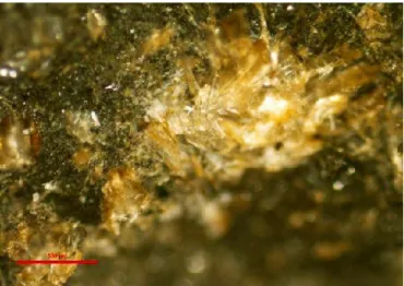
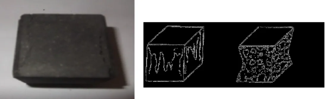
The brake shoe product used by SNTF is a carbon / carbon composite material referred to as "C/C". It consists of a solid carbon matrix reinforced by fibers that are carbon itself. Complementarity and the combination of qualities of the two components that are the fibers and the matrix should give the overall material an interesting mechanical thermal and tribological performance [18]. Figure 1 shows a micrograph of the structure of the C/C carbon-carbon composite. A large number of filaments are grouped within the structure to distribute the local micro defects that may exist within the filament and subsequently obtain a basic wire diameter sufficient for quick handling.
Figure 1:Example of microstructure of the C / C composite
The micrographs of figure 2 and figure 3 show respectively microscopic views of the structure of the material.
Figure 3: Microscopic view of the filament "After the rupture of the material ((100 μm)"
2.2. Physical and mechanical characterizations of constituents 2.2.1. Density measurement
Two methods were used for volumic mass measurement (mv): the classical method and the method of
pendulum. The details of manipulation of these two methods are presented in the reference [18]. The measured values are:
Classical method: mv = 1.66 g / cm3
Pendulum method: mv = 1 g / cm3
There appears to be a fairly a significant divergence between the results given by these two methods. The limited number of measurements as well as the difficulty in the accuracy of the second method may be one of the probable causes of this significant difference. It is interesting to note, however, that the value measured by the first method is very close to the order of magnitude measured by R. Devi and R. Rao [19] on liquid-densified multidirectional C/C composites (unspecified precursor) of 1.8 g / cm3 as well as that
one obtained by C. Taylor [20] on C / C composites densified by different routes which is 1.6 g / cm3.
2.2.2. Rockwell hardness measurement
The test pieces for the Rockwell hardness tests are first prepared by cutting cylindrical samples of 25 mm in height and 20 mm in diameter of the packing at the specified location on the sole of the brake (Fig. 4). They undergo thereafter machining of the back until the disappearance of the entire iron sheet and supports until obtaining a smooth surface parallel to the upper braking surface.
The Rockwell hardness test is performed conventionally in accordance with ASTM Method D 785-65 on an apparatus intended for this use (Fig. 5).
Figure 5: Apparatus used for the classic measure of the hardness
The NF EN ISO 6508-1 standard is also used for this type of test. The latter consists in printing, in two stages, in the surface layer of the specimen, an indenter, which is a diamond cone at a 120 ° angle and a spherical end of diameter 0.2 mm in order to measure the increase issued from the depth of penetration by a direct reading. The use of the cone makes it possible to avoid a large dispersion. These Rockwell Indices can be read directly on the graduated dial. The Rochwell hardness C designated by HRC is expressed by a dimensionless number. Three tests were applied for each sample and the average value is adopted for characterization. Ten samples were tested. The German standard DIN 50-150 has established a specific abacus to deduce Brinell hardness (HB) and Vickers hardness (HV) by conversion from the Rockwell hardness measurement. Furthermore, there is a relationship between the Brinell HB hardness and the tensile strength Rm. For carbon steels: Rm = 3.5 HB. Table 1 summarizes the results obtained from measure and from conversions as well as the standard deviation and the coefficient of variation relative to HRC.
Table1: Measured and converted values of hardnesses.
Hardness HRC HV HB
Average 35,5 350 333
Standard deviation 1,85 - -
Coef. of Variation % 5,2 - -
Despite all the precautions taken during handling, the hardness measurement results show a significant dispersion. This is mainly due to the heterogeneous nature of the material as well as its surface condition that is very difficult to make perfectly smooth despite all the precautionary operations performed in this direction. However, the order of magnitude of this dispersion seems to be acceptable for this type of composite material.
2.2.3. Tribological wear test
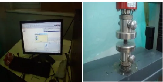
In order to better understand and identify the damage mechanisms that occur on industrial brake shoe devices during travel, tribological tests simulating wear have been performed on a CSM + module / version 4.4U pawn-to-disk tribometer , equipped with a digital display. The acquisition rate is 10 Hz. The entire device connected to a microcomputer presents the results of the variation of the coefficient of friction according to the three parameters of time, displacement and the number of turns. The tests are carried out at a temperature of 25 ° C in an environment characterized by a relative humidity of 50% and are compatible with the standards DIN 50324, ASTM G99 and ASTM G133. The wear rate for the sample is calculated by determining the volume loss per unit traveled distance. The cylindrical samples, diameter 20 mm and height 15 mm are brought into contact with a ball mounted on an elastic arm. Each sample is rotated. The weak deflection of the arm makes it possible to determine the tangential forces and consequently the coefficient induced by this displacement.
2.2.4. Measurement of compressive strength
The specimens for compressive characterization of the material were removed from the shoes are then packaged immediately preceding the test for three days at a temperature of 23 ± 2 ° C and a relative humidity of 50 ± 5%. Two types of tests were used : cubic pieces of 40x40x40 mm3 (Fig. 6 ) and cylindrical samples of 25 mm in height and 20 mm in diameter conform to normative requirements EN 12350-1, EN 12390-1, EN 12390 -2 and EN 12504-. The diameter and height of the samples are measured with an accuracy of 10 μm.
Figure 6: cubic samples used for the compressive characterization tests
The specimens were subjected to the crushing test according to ASTM D695 standard with a compression press with a digital display for the cubic samples. The loading speed is slow and constant and is of the order of 1500 0 KN.s-1. The tests on cylinders are carried out on an universal machine of type ZwickRoell
Z 20 at a travel speed of the crossbar of 5mm/min (Fig.7). The tests are conducted until the samples are completely broken.
2.2.5. Homologation of shear and three-point-bending strength tests (UIC 2006) A- Shear strength
The tests were conducted by adopting a device using a hydraulic press as shown in figure 8 in accordance with the UIC specifications 2006 [6]. An iron sheet was placed between the two sides of the sole to ensure a good transmission of the effort.
Figure 8: Device for the shear test on a hydraulic press
B- Flexural strength
The same device, the hydraulic press was adopted for the mechanical tests of the flexural strength made in accordance with the specifications of the UIC 2006, in order to locate the most fragile parts of the composite shoe [6].
Test N° 1: in accordance with the UIC 2006 requirements concerning the application of a force of about
19 KN for a type K sole [6] and a length of 320 mm, a composite sole was subjected to a monotonous increasing effort applied by a hydraulic press (Fig. 9).
Figure 9: Application of the flexure test number 2
Test N° 2 : this test is used to define the actual cause of the deformation if it is due to the notch separating
the two parts of the sole or if it is a poor quality of the material (Fig. 10).
These two tests are performed each time with new soles. The stress is applied monotonously at a speed of 30 mm / min.
2.2.6 Diagnostic of wear tests and experimental protocols
The approach to conduct the diagnosis adopted is based on on-line tests in order to deduce the probabilities of types of wear and possible causes. It is important to note that the insoles used for the tests must imperatively present the dimensions the original model corresponding to mass production. Each program was carried out with new soles from the same production batch. It is also important to point out that during the tests line, the appearance on the soles of flames, exudation of the binder, permanent and screeching and odors are strictly prohibited.
Moreover, the soles should not crumble or delaminate on an important surface and they should not present damages hindering their mechanical performance. All these precautions were taken and monitored during all the paths of the experiments. In-service tests were performed on a total of 32 wagons with brakes of different designs and used under varying atmospheric conditions winter period and in summer, for several uninterrupted shuttles on the route DjebelOnk -Annaba with a distance of 452 Km on the same vehicle. This course is sufficient to produce anomalies. An investigative system used for years by the SNTF contributed to this measure. It is interesting to note that these in-service tests are conducted to prove that the composite sole in question is used under the conditions indicated for the compliance evaluation, and that it does not cause any deterioration on the wheels and that it does not induce disturbance in the train traffic. For the purposes of the analysis, each observation was symbolized as follows:
A: wear on one side of the shoe - B: acceptable wear (in conformity) - C: abnormal crack or breakage - D: takeoff of the composite from the metal frame of the outsole - X: very advanced wear beyond the wear limit - Y: metal inclusion on the wheel - Z: sole charred or burned.
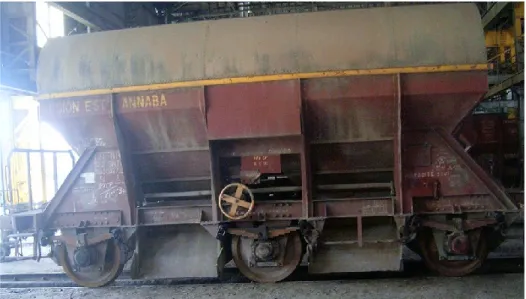
After each course of a train composed of thirty two axle wagons for the transport of phosphates from DjebelOnk (loading site) to Annaba (Maintenance station of replacement of shoes ), the observed wear are thus recorded according to the classification by symbol and this for both winter and summer periods. The 32 cars operated include 256 brake shoes. Each wagon is equipped with 8 clogs. Figure 11 shows an example of an axle wagon used for the transport of the phosphate equipped with 8 shoes with extreme wheels.
3. Results and discussions
3.1. Measure of the coefficient of friction
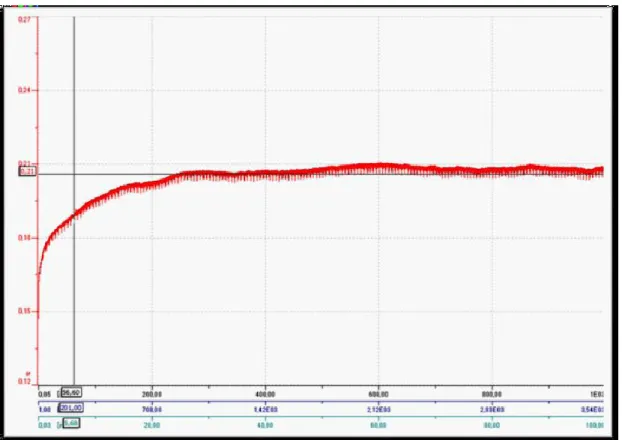
The tracking of the coefficient of friction and wear is an essential aspect in understanding the damage mechanisms that occur on industrial devices such as brake shoes. A typical example of the variation of the coefficient of friction according to three parameters : time, displacement, number of turns is shown in figure 12.
The coefficient of friction increases rapidly at the beginning of the simulation and stabilizes thereafter around a constant value of 0.21 from 200 s. This value remains comparable and consistent with that given by the manufacturer. It should be noted that recent work highlights the importance of the thermal properties of 2D / 3D C/C composites in their performance in braking simulation [11]. FM Kustas et al. [16] note that the friction of the C/C 3D composites at room temperature under vacuum is low compared to the friction obtained with the reference test.
Few results on friction coefficient measurements of carbon fiber reinforced polymers (CFRP) are available in the scientific and technical literature. However, some experimental studies have attempted to explore the effects of normal load, velocity or environmental conditions on the value and variation of the coefficient of friction and on the wear of high modulus and high strength carbon fiber reinforced composite materials [21, 22, 23]. The effects of volume fraction and fiber orientation were also considered [24]. Numerical models of a contact between a fibrous composite and an opposite roughness have been proposed [25].
Figure 12: variation of the coefficient of friction as a function of time, displacement and the number of turns. It should be noted that all these works describe the friction under normal load strong enough to induce a wear of the composite. Experimentally studying the friction between two composite CFP under low normal charge O. Smerdova et al. [26] reported a slight increase in the coefficient of friction with the change of orientation of the fibers of the two composites from parallel to perpendicular to the direction of slip while the proposed analytical model assuming that the actual contact area is made up of a multitude of
micro contacts of three types: fiber-fiber, fiber-matrix and matrix-matrix predicts an independence of this angle. Furthermore, the tests highlight a decrease in the coefficient of friction of half with an increase in the fiber volume fraction Vf from 0% to 62%, which corresponds to the qualifying dependence found in the context of the model.
In a tribological characterization study of an AA5083 aluminum alloy made by a conventional test using a pion-disk tribometer only allowing to determine a Coulomb type friction coefficient, DT Pham et al. [27 ] show, taking into account measurement uncertainties, that the coefficients of friction measured for a variation in speed from 0.0005 m / s to 0.05 m / s and for loads varying from 0.08 N to 0.42 N are not very sensitive to speed except at lower speeds (V = 0.0005 m / s and V = 0.001 m / s) which display smaller coefficients . They conclude that the average value of the Coulomb coefficient stabilizes around 0.2 and that its variation is negligible when the applied load changes. Studying the tribological behavior of organic matrix composites selected for braking applications to ensure a gain in energy evacuation capacity, a reduction in wear and a reduction of unsuspended masses. O. Roussette et al [28] conclude that the instantaneous coefficient of friction shows a level close to the value of 0.35 and a stability compatible with its industrial use at high pressures. An increase in the coefficient of friction at low slip speeds; however, it is noted during experimentation at the end of braking. The study of the physical mechanisms of friction and wear revealed scattered areas of contact on the surface of the pion. An experimental characterization study of the rubbing contact of the packing disk under severe stressing by A. Bulthé [10] reveals a different behavior of the evolution of the coefficient of friction for each of the two braking operations considered. Indeed, during the low energy braking during which the temperatures do not exceed 100 ° C under the friction surface in the disk and in the pad, the coefficient of friction is stable around 0.3 during the first two thirds of the braking before making a significant recovery to reach 0.42 at the time of shutdown.
In the case of high energy stop braking which constitutes a severe contact stress leading to high mass temperatures, 240 ° C and 180 ° C measured at 2 mm below the friction surface respectively in the disc and in the slip, the evolution of the coefficient of friction shows a tribological behavior disturbed during the first part of the braking before stabilizing around the value of 0.28 until the end of the braking.
3.2. Compression behavior of the C / C composite
Figures 13 and 14 show examples of the statement of load-displacement curve obtained during the
compression test for both types of specimens tested. These curves have the same appearance and are linear from the beginning of the test until the total rupture of the sample reflecting the resilient elastic character of the C/C composite. It should be noted that the sampling of cylinders and cubes were made in different locations on different shoes
Figure 14: Compression behavior of the cubic specimen.
Table 2 summarizes the results of measurement of the average compressive stress in compression obtained on cubic and cylindrical specimens as well as the calculated standard deviations.
Table 2: Compressive strength
These results are characterized by a dispersion due to the aspect of the composite material, the dispersion of the mechanical test itself as well as the probabilistic appearance of the fracture for the two test samples. However, the order of magnitude of this dispersion remains acceptable insofar as it is squared in the range of that indicated in the literature for granular composite materials. It is important to point out that the specimens rarely have comparable characteristics because nominally they are not identical because of the heterogeneity at the level of the microstructure as well as the presence of defects of different sizes and densities randomly distributed within the volume of each sample and which are therefore the cause of the ruin of these materials. This can then be triggered at different levels of constraints depending on the orientation, the location, the size and the density of micro-porosities, inclusions, manufacturing discontinuities and weak interfaces and subsequently spread unstable.
Both geometries indicate comparable values. The ratio between the value given by the cylinder and that given by the cube is on average 0.98, which is satisfying. It should be noted that to make an analogy with the concrete material , this ratio on specimens 15/30 for the cylinder and on cubes of 20 cm of concrete edge varies from 0.7 to 0.9 and that an average of 0.83 is then adopted by the European Committee for Concrete for this material [29-30-31]. Finally, it should be noted that the measured values of the stress at break both on the cylinder and on the cube fall within the ranges given by the data sheets of the physical and mechanical characteristics of this type of composite material C/C found in the scientific and technical literature. In spite of their large number, the cylindrical specimens show a dispersion of the values of the resistance greater than those shown by the cubic specimens.
The rupture of the cubic specimens in compression takes place in oblique planes with the formation of two truncated pyramids and opposed by the small base as shown by the examples of this ruin mode in figure15. This mode of rupture is typical on cubic specimens. It is a mechanism similar to that observed on
Number Resistance (MPa) Standard Deviation (MPa) Coef of variation (%) Cylinder 10 85 11 13% Cube 5 86,5 4,8 5,5%
concretes and cement based materials and it is mainly conditioned by the friction forces that develop between the faces of the specimen and the press plates and which are directed inside of the block which stops the development of transverse deformations [31].
Figure 15: example and schematization of the mode of rupture of the cube
The mode of fracture of the cylindrical specimens is shown in figure 16. The mechanism ruin is characterized by the emergence and formation of rupture lines in planes parallel to the direction of the compression load as shown schematically in figure 16. This is an illustrative example of a proper cylinder break.
Figure 16: Example and diagram of the cylinder failure mode
3.3. Results of online trials
32 wagons were operated online including a total of 256 clogs. Each car is equipped with 8 brake shoes. Thus the summation of the different types of wear observed must obey the following parametric equation: Σ N i,j = 256
Ni: number of shoes corresponding to a type of wear i ranging from 0 to 256 J = A, B, C, D, X, Y, Z type of wear observed on each shoe
3.3.1 Winter period
Observations after replacing clogs in the maintenance station of Annaba made on the worn shoes of the two wheels of each axle were raised, collected and stripped. Wear is then quantified using the symbols adopted for their denomination. It should be noted that for each wheel the failures were noted on the two left and right shoes and this for the 3 oars.
The summation of the different wear observed on each shoe was established for the three tests carried out on the three experienced trains. The results give the following equations :
- Second test (2nd train) : 15A+17B+91C+60D+31X+20Y+20Z=256 - Third test (3rd train) : 20A+17B+81C+40D+51X+14Y+33Z=256
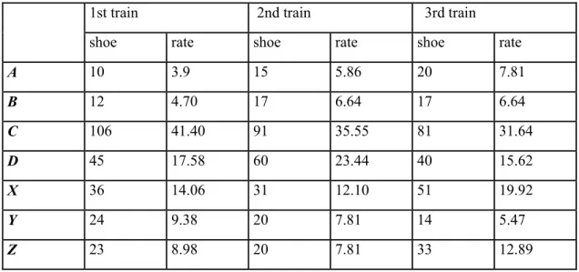
Table 3 summarizes the number of shoes damaged by type of wear and their rate for each train.
Table 3: Rates of different types of wear in winter
1st train 2nd train 3rd train
shoe rate shoe rate shoe rate
A 10 3.9 15 5.86 20 7.81 B 12 4.70 17 6.64 17 6.64 C 106 41.40 91 35.55 81 31.64 D 45 17.58 60 23.44 40 15.62 X 36 14.06 31 12.10 51 19.92 Y 24 9.38 20 7.81 14 5.47 Z 23 8.98 20 7.81 33 12.89
These results are shown in the histogram of figure17.
Figure 17: Histogram of worn shoe rate for different types of wear in winter.
The analysis of the results of recorded measurements makes it possible to draw the following observations: - Type of wear (A) : wear on one side of the shoe is at a rate varying from 3,9 to 7,81. This type of wear is generally due to the geometrical defects of the soles. It may also be caused by a defect in the keying device of the fastener as shown in figures 18 and 19:
Figure 18: Fixing device Figure 19: worn shoe
-Type of wear (B) : [4.7 - 6 .64] : few soles wear out according to the requirements of the manufacturers, demonstrating that this is a serious shoe quality problem
- Type of wear (C) : [31.64 - 41.40] : this case of wear is widespread as confirmed by the high rates measured. It has even been noted that the propagation of the crack is often systematic from the notch separating the two parts of the soles and which has been created for a better dissipation of the heat resulting from the sole-wheel friction (Fig. 20 and Fig.21).
Figure 20: cracked sole Figure 21: Sole from the notch
- Type of wear (D): [15,62 – 23,44]: this type of wear reflects a non-conformity of the connection of the composite with the reinforcement, which causes damage to the shoe-holder and even the wheels (Fig. 22).
- Type of wear (X) : [14.06 - 19.92] : usually this type of wear is rarely encountered in similar climatic conditions (Fig. 23). Its consequences sometimes cause very serious incidents on-line including brake failure as even the slack adjuster cannot catch the sole link wheel-shoe
Figure 23: Exceptional wear of shoe
-type wear (Y) : [5.47 - 9.38] : this type of abnormality is based on the different types of wear (C, D, X). This anomaly can also generate on-line derailments because it sometimes causes overheating and aggressiveness at the wheel running gear (hot box).
-type wear (Z) : [7.81 - 12.98] : regardless that this burning defect is unacceptable, the first finding of expertise of these burned soles, shows a bad smell. Therefore a chemical analysis is required to determine if the material contains any toxic minerals such as asbestos or other.
3.3.2. Summer time
The same types of tests of the winter have been conducted during the summer months of June, July and August for three oars in order to observe the influence of temperature on the nature and degree of wear on the shoes. The observed results were also gathered, counted and classified. Table 4 summarizes the number of damaged shoes by wear nature and rate for each train as in the case of the winter.
Table 4: Rates of different types of wear in summer
1st train 2nd train 3rd train
shoe rate shoe rate shoe rate
A 5 1,95 8 3¸12 2 0¸78 B 8 3¸12 7 2¸73 5 1¸95 C 30 11¸71 40 15¸62 25 9¸76 D 47 18¸35 38 14¸84 51 19¸92 X 58 22¸65 61 23¸82 67 26¸17 Y 38 14¸84 35 13¸67 23 8¸98 Z 70 27¸34 67 26¸17 83 32¸42
Figure 24: Histogram of the rate of worn shoes of different types of wear in the summer.
In order to objectively analyze these results, a comparison between the two periods better explains the influence of temperature on wear clogs.
-type wear (A):the wear rate compared to the winter period is almost the same. The realignment of the mechanical linkage is not related to climate change.
-type wear (B):in contrast to the wear, the wear rate in conformity with this period is almost zero. Thus, the behavior of composite brake blocks during the summer is poor compared to the winter period.
-type wear (C):the presence of cracking shoe levels persists but with small percentage. The reduction in temperature promotes the breakage of the composite.
-type wear (D):a same percentage is recorded for two periods.
-type wear (X):light influence of temperature on the soles damage beyond the wear limit is recognized. The increase in temperature has caused the soles wear out more quickly during the summer and before the train reaches the planned route. The wear of the shoes exceeds the limit.
-type wear (Y) : there is an appearance of hot tears to levels of a very large number of wheels. This can cause paralysis of traffic and even lead to accidents.
-type wear (Z) : the observations of the braking edge during this period and descents indicate a creation of a red spark between the wheel and the sole. These observations explain very well the percentage of such wear. We spend an average of 10.15 during the winter period and 28.64 rate in summer.
3.3.3. Finding
From the observations made in both periods, the following observations can be made :
- For wear A and according to the geometrical characteristics of the soles, the fastener does not appear to meet the standards in force (p.ex.ISO- 2768) [1].
- For wear B, a very small number of sole wears as required.
- Wear C is a type contrary to probate rules soles. According to the UIC standards [6] a sole according would have withstood the bending and shear stresses, which was not the case for these types of soles that have cracks and breaks at least the braking forces.
- To wear D, contrary to what was required by the regulations in force, a good assembling composite-rear plate was not assured. That is certainly explains the ease of launch of the composite of the metal frame.
- The same observations can be made for wear X: a composite sole according never wear out beyond its wear limit, which is 10 mm in accordance with a mileage 45000Km course.
- According to the Y wear, it may be that of a poor sole for the simple reason that the potential life of the wheels is 1200 000 Km while this type of shoe attacks wheels causing repelled at distances much smaller. - The Z wear is now the sum of all failures because its health effects are harmful because of released materials. This type of shoe is a real danger for the user especially when transporting fuel tank.
3.4. Results of mechanical testing 3.4.1. Results of the shear test
To close the application of tangential force in the space of 4 S on a regular basis as recommended by UIC in 2006 [5], a bending of the sole was noticed as soon as a maximum value of 15 KN of the applied force is reached. The sole has broken abruptly (Fig. 25 and Fig.26).
Figure 25: Result of shear tests Figure 26: assembly (sheet-composite) taken off This experiment highlights the bad connection between the back (plate) and the composite material. This is consistent with the test results on-line.
3.4.2. Results of the bending tests
Type 1: after application of a load (the first development effort after 4 S) base began to rapidly flex and
even before the load reaches 10 KN, the sole has broken just medium and an abrupt manner (Fig. 27). It is clear from the observations found that plastic deformation appears and the notch being in its presence the seat of high stress concentrations promotes crack propagation.
Figure 27: Result of the Type 1 flexural test
Type 2: same findings of Test No. 1 of the reflection on the homogeneous part of the shoe have been
Figure 28: Result of the type2 test of flexion
4. Conclusion
Measurements of physical and mechanical characteristics of the C / C composite with an organic matrix show a characteristic dispersion of the composite aspect of the material. This is mainly due to the heterogeneous aspect of this type of material. The resistance values measured on cubic and cylindrical samples are convergent and fall within the order of magnitude of those reported by the scientific and technical literature.
The establishment of the wear tests conducted on a tribometer to simulate the operation of the industrial device of the brake shoes composite material C / C by a representative braking tests on tribometer with respect to the service brake are enabled evaluating the variation in friction coefficient with time. The diagnostic failure analysis of composite brake blocks shows that the study of their on-line behavior that is to say during operation reveals abnormal wear and damage compared to ordinary aging. Bending and shear tests show the breakup of the product and highlight its non-compliance with the rules. To this end, and following the data collected at each stage of this study, it is clear that the product "composite blocks" currently used does not yet meet the standards and rules and urgent measures must be taken by the National Company of Railway Transportation (SNTF – Algeria) to cope with this situation, by registering very large expenditure items and by developing new innovative composite materials based on high performance resistant resins reinforced with suitable resistant fibers. In perspective, industrial investigations should focus on improving the performance of braking systems by seeking to better understand the durability of new friction composite materials under severe stress by a better understanding of the interactions between the physical phenomena of friction, their multi-scale and multi-physical natures as well as the transient nature of braking.
Thanks
The authors would like to thank Annaba's regional rail transport department (SNTF) and especially its material service for all the facilities granted at its premises and workshops as well as the management of the Annaba National School of Mines and Metallurgy (ENSMMA). ) for the assistance provided when using the equipment of their laboratories.
References
[1] Normes Internationales : Organisation internationale de normalisation (ISO)
1) 17025:2005 : Exigences générales concernant la compétence des laboratoires d’étalonnages et d’essais, 2005
2) 2768-1:1989 : Tolérances générales - Partie 1 : Tolérances pour dimensions linéaires et angulaires non affectées de tolérances individuelles, 1989.
3) 2768-2:1989 : Tolérances générales - Partie 2 : Tolérances géométriques pour éléments non affectés de tolérances individuelles, 1989.
[2] X. Bourrat, “Structure in carbons and carbon artefacts”, Science of carbon materials, H. Marsh and F.Rodriguez-Reinoso, Pub. Universidad de Alicante, 1999, pp. 1-97.
[3] X. Bourrat X., A. Oberlin & R. Bachelard, Carbon, 31, 2, 1993, pp. 287-302.
[4] A. Fillion, “Composites C/C et C/C-SiC pour applications tribologiques”, Thèse de Doctorat de l’Université de Bordeaux I, France, n° 2168, 2000.
[5] Fiches UIC : Union Internationale des Chemins de fer (UIC)
1) Fiche UIC n° 541-1 : Frein - Prescriptions concernant la construction des différents organes de frein, 6e édition, novembre 2003.
2) Fiche UIC n° 541-4 : Frein - Freins avec des semelles de frein en matière composite, 2e édition du 01.10.90 et 3e édition du 1er avril 2006.
3) Fiche UIC n° 544-1 : Frein - Performance de freinage, 4e édition, octobre 2004.
[6] Normes Européennes : Commission Européenne (CEE) Directive européenne 91/155/CEE de la Commission définissant et fixant, en application de l’article 10 de la directive 88/379/CEE du Conseil, les modalités du système d’information spécifique relatif aux préparations dangereuses, 5 mars 1991, JO L 076 du 22/03/1991.
[7] N. Benseddiq « optimisation des garnitures composites pour les freins a disques ferroviaires » thèse de doctorat, Université de Lille 1, Laboratoire de mécanique de Lille EUDIL, 08 avril 1997, 152pages, France.
[8] M. Baklouti « analyse tribologique du rôle de constituants dans les performances de matériaux composites organiques pour garnitures de frein » thèse de doctorat délivré simultanément par l’école centrale de Lille et l’école nationale d’ingénieurs de Sfax dans le cadre d’une cotutelle internationale, 26 novembre 2013, 158 Pages.
[9] N. Hentati « matériaux composites a matrice organique pour garnitures de frein, microstructure, les propriétés et le comportement tribologique » thèse de doctorat ,ecole centrale de Lille, 26 décembre 2015, 160 pages.
[10] A. L. Bulthé ”Caractérisation expérimentale du contact frottant disque garniture sous sollicitations sévères de freinage. Prise en compte des interactions tribologique, thermique et physico-chimique”, Thèse de doctorat, Mécanique, N°d’ordre 39, Ecole Centrale de Lille et Université des Sciences et Technologies de Lille, Lille 29 novembre 2006, France, 144p.
[11] G. Lu, P. Cui., Q. Wang, “Influence of structure of the reinforcement in C/C composite on its friction and wear behavior”, Proc. Conf. Carbon 2002, Shanxi Chungin Audio-Visual Press Ed., Beijing, 15-19 Sept. 2002.
[12] M. Godet “The third body approach, a mechanical view of wear”, Wear 100, 1984, pp. 437-452.
[13] Y. Berthier, M. Godet,The Third Body Concept Interpretation of Tribological Phenomena. Tribology Series, 31 Editor: D. Dowson Proceedings of the 22nd Leeds-Lyon Symposium on Tribology held in the “Laboratoire de Mecanique des Contacts”, Institut National des Sciences Appliquées de Lyon, France, 5th-8th September 1995, 760 pages.
[14] Y. Berthier, « Background on friction and wear” in Lemaître Handbook of Materials Behavior Models, Academic Press, Section 8.2. 2001, pp. 676-699
[15] S. Descartes, Y. Berthier, “Rheology and flows of solid third body: background and application to an MoS1.6 coating”, Wear, 252, 2002, pp. 546-556.
[16] F.M. Kustas, R.R. Hanson, J.L. Summer, “Tribological performance of 3D carbon-carbon composite », Composites Part I: Ambient Environment, Lubrication Engineering, 1995, Vol. 51. (7), pp. 599-604.
[17] K. Anand, V. Gupta, «The effect of processing conditions on the compressive and shear strength of 2D carbon-carbon laminates », Carbon, 1995, vol. 33, N° 6, pp. 739 - 748
[18] I. Benbrinis, B. Redjel » Caractérisation expérimentale physico mécanique et étude tribologique des sabots de frein en matériau composite C/C à matrice organique des wagons SNTF », Revue « Nature & Technologie ». A- Sciences fondamentales et Engineering, n° 16/ Janvier 2017, pages 01 à 12.
[19] G. R. Devi, K. R. Rao, “Carbon-carbon composites – an overview”, Defence Science Journal, 43, 4, 1993, pp. 369-383. [20] C. Taylor, “Carbon matrix composites » Comprehensive Composite Materials, A. Kelly, C. Zweben, R. Warren (Eds), PergamonPress, 4, 2000, pp. 387- 426.
[21] M. Beaumont, T.N. Farris, C.T. Sun, « Scratch testing of advanced composite surfaces », Composites Part A, Vol. 28A, 1997, pp. 683-686.
[22] B.S. Tripathy, M.J. Furey, «Tribological behavior of unidirectional graphile-epoxy and carbon-PEEK composites ». Wear, Vol. 162-164, 1993, pp. 385-396.
[23] B. Suresha, G. Chandramohan, « Effect of normal load and sliding velocity on friction and wear behavior of carbon fiber reinforced epoxy composites ». Journal of reinforced plastics and composites, Vol. 26, 2007, pp. 1695-1703.
[24] H.H. Shim, O.K. Kwon, S.R. Youn, «Effects of fiber orientation and humidity on friction and wear properties of graphite fiber composites », Wear. Vol. 157, 1992, pp. 141-149.
[25] X. Ning, M.R. Lovell, « On the sliding friction characteristics of unidirectional continious FRP composites ». Journal of tribology, Vol. 124, 2002, pp. 5-13.
[26] O. Smerdova, A. Le Bot, J. Cayer-Barrioz, B. Sarbaev, “Frottement des matériaux composites polymères a renfort de fibre de carbone : expériences et modélisation”, AMAC- Comptes Rendus des JNC 17 – Poitiers-futuroscope 15-17 Juin 2011, France, pp.178. <hal-00597754>.
[27] D. T. Pham, A. Gavrus, H. F. tancillette” Conception d'un nouveau test de frottement pour le forgeage à froid par extrusion et études tribologiques d'un alliage d'aluminium” 20ème Congrès Français de Mécanique CFM 20, Besançon, 29 Août au 2 Septembre 2011, France.
[28] O. Roussette, Y. Desplanques, G. Degallaix, M. Minet, Y. Gallo « Comportement tribologique en freinage à haute énergie de garnitures en matériaux organiques ».
[29] F. Gorisse, «Essais et contrôle des bétons », Editions Eyrolles, Paris, France, 1978.
[30] F. Gorisse, «Les essais mécaniques » in le béton hydraulique, Presses de l’ENPC, Paris, France, 1982, pp. 379-381.
[31] F. Chellali, B. Redjel, “La pratique des essais destructifs : l’essai d’écrasement du béton », Algérie – Equipement, Revue Technique de l’ENTP, N° 41, Mai 2006, pp. 16-20.