Publisher’s version / Version de l'éditeur:
ECS Transactions, 16, 43, pp. 127-140, 2009-12-01
READ THESE TERMS AND CONDITIONS CAREFULLY BEFORE USING THIS WEBSITE.
https://nrc-publications.canada.ca/eng/copyright
Vous avez des questions? Nous pouvons vous aider. Pour communiquer directement avec un auteur, consultez la
première page de la revue dans laquelle son article a été publié afin de trouver ses coordonnées. Si vous n’arrivez pas à les repérer, communiquez avec nous à PublicationsArchive-ArchivesPublications@nrc-cnrc.gc.ca.
Questions? Contact the NRC Publications Archive team at
PublicationsArchive-ArchivesPublications@nrc-cnrc.gc.ca. If you wish to email the authors directly, please see the first page of the publication for their contact information.
NRC Publications Archive
Archives des publications du CNRC
This publication could be one of several versions: author’s original, accepted manuscript or the publisher’s version. / La version de cette publication peut être l’une des suivantes : la version prépublication de l’auteur, la version acceptée du manuscrit ou la version de l’éditeur.
For the publisher’s version, please access the DOI link below./ Pour consulter la version de l’éditeur, utilisez le lien DOI ci-dessous.
https://doi.org/10.1149/1.3114954
Access and use of this website and the material on it are subject to the Terms and Conditions set forth at
The influence of galvanic coupling on corrosion of carbon steel coupled with stainless steels for use in concrete structures
Qian, S. Y.; Qu, D.
https://publications-cnrc.canada.ca/fra/droits
L’accès à ce site Web et l’utilisation de son contenu sont assujettis aux conditions présentées dans le site LISEZ CES CONDITIONS ATTENTIVEMENT AVANT D’UTILISER CE SITE WEB.
NRC Publications Record / Notice d'Archives des publications de CNRC:
https://nrc-publications.canada.ca/eng/view/object/?id=95daf05a-1868-4336-a99b-2db851dbedf6 https://publications-cnrc.canada.ca/fra/voir/objet/?id=95daf05a-1868-4336-a99b-2db851dbedf6
http://www.nrc-cnrc.gc.ca/irc
T he influe nc e of ga lva nic c oupling on c orrosion of c a rbon st e e l c ouple d w it h st a inle ss st e e ls for use in c onc re t e st ruc t ure s
N R C C - 5 2 7 1 1
Q i a n , S . Y . ; Q u , D .J a n u a r y 2 0 1 0
A version of this document is published in / Une version de ce document se trouve dans:
ECS Transactions, 16, (43), pp. 127-140, December 01, 2009, DOI:
10.1149/1.3114954
The material in this document is covered by the provisions of the Copyright Act, by Canadian laws, policies, regulations and international agreements. Such provisions serve to identify the information source and, in specific instances, to prohibit reproduction of materials without written permission. For more information visit http://laws.justice.gc.ca/en/showtdm/cs/C-42
Les renseignements dans ce document sont protégés par la Loi sur le droit d'auteur, par les lois, les politiques et les règlements du Canada et des accords internationaux. Ces dispositions permettent d'identifier la source de l'information et, dans certains cas, d'interdire la copie de documents sans permission écrite. Pour obtenir de plus amples renseignements : http://lois.justice.gc.ca/fr/showtdm/cs/C-42
The Influence of Galvanic Coupling on Corrosion of Carbon Steel Coupled with Stainless Steels for Use in Concrete Structures
S. Qiana and D. Qub a
Urban Infrastructure, Institute for Research in Construction National Research Council Canada, Ottawa, Canada, K1A 0R6 b
Department of Advanced Material Chemistry, College of Science & Technology, Korea University Sejong Campus Jochiwon, Chungnam Korea, 339-700
ABSTRACT
The judicious use of stainless steel and carbon steel in concrete structures—using stainless steel only in areas with a high risk of corrosion and carbon steel in low-risk areas—could be a viable option for reducing lifetime cost, and extending service life. However, the concern about the risk of galvanic corrosion between the two different steels has prevented this application in the field. This paper investigates the galvanic coupling behaviours of carbon steel and three different stainless steels (304LN, 316LN and 2205). The results indicate that the oxygen reduction reaction is a rate-determining step and is much lower on stainless steel than on passive carbon steel. Therefore, the galvanic coupling current between stainless steel and corroding carbon steel is lower than the coupling current between passive and corroding carbon steels. Consequently, the combination of stainless steel with carbon steel will not increase the risk of corrosion of carbon steel.
Introduction
Corrosion of carbon reinforcing steel in concrete structures such as highway bridges and parking garages can bring about major problems in terms of reduced safety and serviceability for the structures as well as increased rehabilitation costs. Stainless steel has been used to avoid or minimize reinforcement corrosion in many structures due to its superior corrosion resistance. The use of this reinforcement, however, is still limited, partially because of its high initial cost. A potential economical approach is to use stainless steel in the areas of a structure that are most vulnerable to corrosion attack (e.g. top reinforcing steel mat of bridge decks, lower section of a pier or a splash zone). This might significantly extend the service life of a concrete structure with only a slight increase in initial cost. Considering the superior corrosion resistance of stainless steel rebars, its use would also facilitate a reduction in the concrete cover thickness, thereby lowering both the concrete cost and total weight of the structure. In some cases the initial cost increase can be offset by as much as 100% using this approach. Furthermore this approach can also be used in the repair of deteriorated concrete structures. While, there has been considerable interest in the use of stainless steel in selective structural areas, concerns about galvanic corrosion when dissimilar steels are in direct (electrical) contact within concrete structures have prevented its widespread application. As a result, engineers are hesitant to use stainless steel and carbon steel in the same concrete structure.
At present, there are limited studies investigating the potential galvanic corrosion between stainless and carbon steels. In addition, the results of some of the studies are contradictory, making this a rather controversial issue. For instance Webster1 concluded that corrosion could take place if two different steels were connected electrically. He suggested that it would be necessary to isolate the electron transfer path between the anode and cathode to prevent corrosion damage due to galvanic coupling. Seibert2 stated that coupling carbon steel with stainless steel reinforcement is inadvisable, as galvanic coupling will initiate corrosion of the carbon steel.
On the other hand, Knudsen et al.3,4, Klinghoffer et al.5, and Cochrane4 demonstrated that using carbon steel with stainless steel did not increase the risk of corrosion to carbon steel as long as both steels were in a passive condition. Bertolini and co-workers6-, ,
7 conducted their experiments on concrete specimens and concluded that the use of stainless steel in connection with carbon steel did not increase the risk of corrosion of passive carbon steel. They stated that when both carbon steel and stainless steel are in a passive condition, the galvanic coupling current did not produce appreciable effects, since these two types of steel had almost identical corrosion potentials. Galvanic coupling with stainless steel can increase the corrosion rate of active carbon steel reinforcement in chloride contaminated concrete, but this is not worse than the coupling with passive carbon steel. Hope8 reached a similar conclusion in his investigation and concluded that high and potentially damaging corrosion rates would arise in galvanically coupled carbon steel and stainless steel 316 or 2205 if the concrete surrounding the carbon steel became chloride contaminated or carbonated. These corrosion rates were likely to be similar to, or somewhat lower than, the corrosion rates, which would develop if only carbon steel were used.
To investigate the effects of placing stainless and carbon steel in contact with each other, a study was performed to determine the galvanic coupling effect between carbon steel (CS) and stainless steel (SS), specifically 304LN, 316LN and 2205 in both electrochemical cells containing saturated calcium hydroxide [Ca(OH)2] solution and within concrete specimens. Sodium chloride (NaCl) was introduced into the solution during the experiment or premixed in the concrete to simulate aggressive environmental conditions in the field. The galvanic coupling currents between corroding CS and SS were measured and compared to those between corroding CS and passive CS, which always surrounds the corroding area in the field. A quantitative evaluation of the changes of corrosion rate on corroding CS as a result of galvanic coupling is provided. The galvanic behaviour between passive CS and SS was also studied to examine whether this coupling could initiate the corrosion of CS. The anodic/cathodic behaviours of individual CS and SS were also investigated.
Experiments
The steel electrodes were machined from the commercially available reinforcements of carbon steel (CS) and three types of stainless steel (2205, 304LN and 316LN) to two sizes: size (i), consist of small samples of 15 mm in length and 9.4 mm in diameter; and size (ii), consist of large samples of 70 mm in length and 12.5 mm in diameter. The samples of CS and SS were connected by a steel rod as the electric conductor and then embedded in epoxy resin, leaving a fixed area of steel surface (0.7 cm2 for size 1 and 28.6 cm2 for size 2) exposed to the solution. The electrode samples were final polished with
#600 silicon-carbide papers, degreased by acetone and de-ionized water and then immersed in saturated Ca(OH)2 solution with a pH of 12.6 for one week. The corroding CS samples were prepared by placing them in a humidity room to allow the accumulation of rust on their surfaces.
A solution of saturated Ca(OH)2 or a solution of saturated Ca(OH)2 + 3 wt% NaCl was used for the experiments. Solutions were prepared with de-ionized water (≥ 18.2 MΩ·cm, Milli-Q). High purity argon or oxygen was used in some experiments to purge or increase, respectively, the content of oxygen in the solution.
The electrochemical experiments consisted of cyclic voltammetry, linear polarization, potential dynamic, AC impedance and galvanic coupling measurements. All tests (except the galvanic coupling tests) were conducted in three-compartment electrochemical cells. The working electrode was the steel sample. The counter electrode was made of platinum foil or mesh. The reference electrode was a saturated calomel electrode (SCE). A Luggin capillary was used to reduce the IR drop. The cyclic voltammetry, linear polarization and potential dynamic measurements were carried out using a Solartron 1480 MultiStat or Solartron SI 1287 Electrochemical Interface, which was controlled by a PC computer using Corr-Ware software. The IR drop was measured by the AC impedance, which was performed by a Solartron SI 1287 Electrochemical Interface coupled with a SI 1260 HF Frequency Response Analyzer (FRA) and controlled by a PC computer with Zplot and Zview software.
Cyclic voltammograms were measured in the potential range of –1.2 V to +0.5 V (initiated from open circuit potential) with a scan rate of 20 mV/s. Potential dynamic tests were measured from the open circuit potential to –0.65 V. The scan rate was 0.1 mV/sec. The electrochemical polarization resistance (Rp) and the corrosion rate (Icorr) of the
reinforcing steel were determined using the linear polarization technique in the electrochemical cell. The potential of the steel electrode was scanned at a slow rate of 0.01 mV/s in the range of ±10 mV around the corrosion potential, Ecorr.
The galvanic coupling experiments were carried out using an apparatus consisting of two cells connected by a salt-bridge. The galvanic coupling current was measured and recorded by coupling the two steels (having ratio of 1:1 in surface areas) using a Keithley 485 Picoammeter operated by a PC computer using VEE Pro software. The salt bridge was made of a U-shaped glass tube with an internal diameter of either 9.4 mm or 3.1 mm. The two ends of the U-shaped glass tube were sealed by a Celgard® 2500 micro porous membrane to prevent solution flow and slow down chloride ion diffusion. The glass tube was filled with a saturated Ca(OH)2 solution with or without 3 wt% NaCl depending the experimental conditions.
Concrete specimens were made of ordinary Portland cement with a weight ratio of water: cement: sand: aggregate = 0.5: 1: 2: 3. Different amounts of NaCl were added to the concrete mixtures. In each specimen, two rebars were embedded in parallel within concrete specimens. Two ends of each rebar were coated with epoxy resin and covered by a shrinkable plastic sleeve leaving a length of 15 cm (surface area ≈70.7 cm2) exposed to the concrete. The concrete mixtures were cast into acrylic molds, and were cured for 35 days in a curing room with an environment of 95% ± 5% relative humidity and 22 oC ± 2 oC.The specimens were then placed in an environmental chamber with 80% relative
humidity, where the temperature was cycled between 25oC and 45oC (was cycled between 25oC to 50oC after the 220th day) to accelerate the rebar corrosion during the two-year test period.
Results and Discussion Galvanic Coupling Current Density
A galvanic current occurs when two different steels such as carbon steel (CS) and stainless steel (SS) are connected in the same electrolyte. During this galvanic coupling, the potentials of two steels are forced to shift to a new common value. The potential difference between these two steels is the driving force for the galvanic current. The steel that originally had a more negative potential (usually corroding CS) is subjected to an oxidation process (anodic process). The more noble steel (usually SS), which originally had a more positive potential, is polarized to the more negative potential and subjected to a reduction (cathodic) process. The electron transfer through the steels from the active steel (anode) to the noble one (cathode) yields the galvanic current.
Figure 1 shows the galvanic coupling current densities (Igc) measured by connecting
corroding CS with passive CS or SS (2205, 304LN and 316LN) with the same electrode size (i.e. the ratio of apparent electrode surface area is 1:1). The current densities decreased gradually until they reached a stable value after the initial pulse, which was caused by the current charge for the double layer in the interface between steel and electrolyte. Figure 1 clearly shows that the galvanic coupling current between the corroding CS and SS is less than half of that between corroding CS and passive CS.
To calculate the percentage increase in the corrosion current density as a consequence of galvanic coupling, a comparison between the increase in the corrosion
Figure 1. Igc measured by coupling corroding CS with passive CS or SS alloys in a
current density, ∆Icorr and the original corrosion current density, Icorr is needed. It is
important to note that ∆Icorr from the coupling between corroding CS and SS should be
compared to that resulting from the coupling between corroding CS and passive CS, since the latter situation always exists in concrete structures even within the same rebar. If the galvanic current between corroding CS and SS is smaller than that between the corroding and passive CS, then the use of SS, which is in electrical contact with CS in a concrete structure, will not increase the risk of CS corrosion.
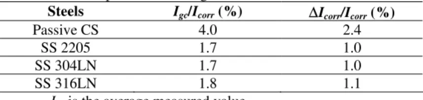
The corrosion rate of the corroding CS was measured by the linear polarization technique and was found to be 13.3 ± 0.4 µA/cm2 at the corrosion potential of –0.6 V vs SCE. The percentage increases of Igc between the corroding CS and the passive CS or the
SS over the corrosion current density of corroding CS at this potential are listed in Table I. Based on the experimental results showing that the Tafel slopes of anodic and cathodic polarization on corroding CS are 40 mV/decade and 60 mV/decade, respectively, the measured Igc is known to partially compensate (about 40%) for the decrease in the
cathodic current and contribute partially (about 60%) to the increase in the corrosion current density, ∆Icorr, on the corroding CS due to the coupling effect. Therefore, the
corrosion rate increase is about 2.4% due to the galvanic coupling between corroding CS and passive CS and is only about 1.0% due to the galvanic coupling between the corroding CS and SS. Since the galvanic coupling effect introduced by SS is about 1% and smaller than that of passive CS, galvanic coupling between SS and CS will not increase the risk of CS corrosion.
TABLE I. Relationship between Igc and Icorr for various steels
coupled to corroding CS at –0.6 V vs SCE
Steels Igc/Icorr (%) ∆Icorr/Icorr (%)
Passive CS 4.0 2.4
SS 2205 1.7 1.0
SS 304LN 1.7 1.0
SS 316LN 1.8 1.1
Igc is the average measured value.
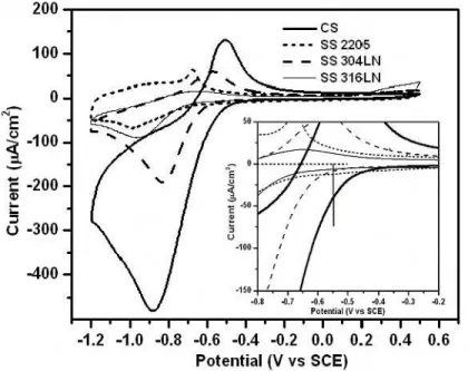
Effect of Oxygen on Cathodic Reduction Current
The oxygen reduction and oxidation reaction behaviours of passive CS and SS 2205, 304LN and 316LN were examined by a cyclic voltammetry technique, with the results shown in Figure 2. The cathodic and anodic current densities on all SS were significantly smaller than those on passive CS. The corrosion potential of the corroding CS is about – 0.55 V to –0.6 V. Therefore, the galvanic coupling potential of corroding CS with passive CS or SS should be at this potential range and the reactions on passive CS or SS are cathodic reductions. From the inset of Figure 2, it can be seen that the cathodic reduction current densities of all SS are much lower than that on the passive CS in this potential range. Clearly, the SS surface is not favourable for the oxygen reduction reaction.
The effect of dissolved oxygen on the cathodic reduction current density of passive CS electrodes was examined in an electrochemical cell. First, a cyclic voltammogram was measured in the cell open to the air; then oxygen was bubbled into the cell to saturate the solution and another cyclic voltammogram was measured. Subsequently, the solution in the cell was degassed by bubbling argon into the cell to remove the dissolved oxygen, and another cyclic voltammogram was measured, as shown in Figure 3.
Figure 2. Cyclic voltammograms of passive CS and SS measured in a saturated Ca(OH)2 solution (the inset shows an enlarged current scale around the coupling potential).
Figure 3. The cyclic voltammograms of passive CS under various oxygen conditions.
The cathodic current peak [attributed to ferric to ferrous transformations9
(FeOOH/Fe(OH)2)] had the smallest peak with a value of –180 µA/cm2 at –0.72 V when oxygen was purged from the solution. The areas (i.e. electric charges involved in the electrochemical reactions) of this cyclic voltammogram for the cathodic and anodic scans are almost equal, indicating that both reactions are mainly for the electrode surface reduction and oxidation. When oxygen content was increased (cell open to the air), the
cathodic current peak increased to a value of –330 µA/cm2 at –0.87 V. When the
concentration of oxygen in the solution was further increased (saturated by bubbling oxygen), the peak in cathodic current increased further to a value of –400 µA/cm2 at –1.0 V. The electric charge for the cathodic reduction also increased and indeed, became much larger than that for anodic oxidation, indicating that there was a significant oxygen reduction reaction involved.
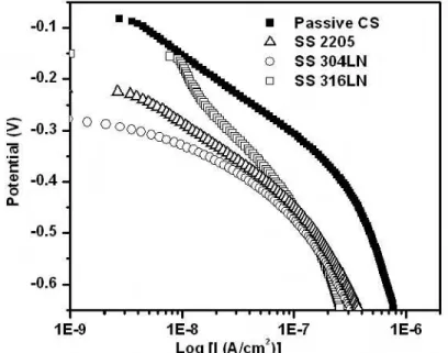
Figure 4 shows the cathodic polarization curves for passive CS and SS. The cathodic current densities on SS are all much smaller than those on passive CS in the region of –0.5 V to –0.6 V. As described above, Igc is limited by the cathodic reduction reaction on
the passive CS or SS when the corroding CS is coupled with them. Therefore Igc induced
by SS is much smaller than that induced by the passive CS when these steels are coupled with corroding CS.
Figure 4. Cathodic polarization curves of passive CS and SS measured in saturated Ca(OH)2 solution.
Effect of Resistance of Salt Bridge
The changes in the values of galvanic current density with the resistance of the salt bridge measured in an electrochemical cell are shown in Table II. When the resistance of the salt bridge increased from 0.9 KΩ to 33.0 KΩ, Igc decreased from 0.44 µA/cm2 to
0.18 µA/cm2 for the coupling between passive CS and corroding CS and from 0.20
µA/cm2 to 0.05 µA/cm2 for the coupling between SS 316LN and corroding CS. It is clearly shown that Igc decreased when the resistance of the salt bridge increased since the
high IR drop arising from this resistance reduces the driving force for galvanic coupling. It is important to note that Igc introduced by SS 316LN is always much smaller than that
induced by passive CS for the same resistance of the salt bridge, regardless of the resistance. The changes in resistance from 0.9 KΩ to 33.0 KΩ cover quite a wide range of concrete resistivity, which correspond to a wide range in the rebar corrosion rate (from low to high).10 Therefore, a change in Igc with an increase in resistance in the salt bridge
has a practical importance for simulating the resistivity change in the concrete (i.e. the galvanic current density can decrease significantly with increased concrete resistivity).
TABLE II. Igc (µA/cm2) measured by galvanic coupling experiments in an electrochemical
cell with different salt bridge resistances
Resistance of salt bridge (KΩ) 0.9 2.3 33.0
Passive CS coupled with corroding CS 0.44 0.32 0.18
Galvanic Coupling Between Passive CS and SS
For most concrete, the pH of the pore solution ranges from 12.5 to 13.5. As a consequence of its high alkalinity, CS and SS are both in the passive condition after they are cast into concrete. Therefore, the corrosion potentials, Ecorr, of these steels are quite
similar and can be connected to each other without the initiation of corrosion on CS. Measurements of Ecorr and the galvanic coupling current densities were performed in a
saturated Ca(OH)2 solution in the absence of NaCl, as shown in the first two data columns in Table III. The corrosion potentials were very close to –0.08 V for passive CS and between –0.15 V and –0.27 V for SS. While the Igc is approximately 1.48 nA/cm2
when coupled between two passive CSs, it falls below 1 nA/cm2 when coupled between passive CS and different SS as shown in the first column of data in the Table III.
TABLE III. Corrosion potentials and Igc between the passive CS and SS in saturated Ca(OH)2 solutions
with and without 3 wt% NaCl
Sat. Ca(OH)2 Sat. Ca(OH)2 + 3 wt% NaCl
Steel coupled with
passive CS Igc (nA/cm2) Ecorr (V) Igc (nA/cm2) Ecorr (V)
Passive CS 1.48 -0.08 -- --
SS 2205 -0.75 -0.22 -0.77 -0.32
SS 304LN -0.66 -0.27 -0.83 -0.32
SS 316LN -0.87 -0.15 -1.05 -0.28
When the CS reinforcement is substituted with SS in the critical areas, SS is very likely to be in an environment with a high chloride concentration. Experiments simulating this condition were tested by the addition of 3 wt% NaCl to the solution in the SS side and the results are shown in the last two data columns of Table III. It was found that the open circuit potentials were shifted slightly to more negative values. Moreover, the values of Igc were also increased slightly but remained very low, around 1 nA/cm2,
even though the SS was exposed to chloride ions. It is important to note that these values are less than Igc induced by the coupling of two passive CS electrodes.
An Igc value of 10 nA/cm2 is considered to be the long-term maintenance-free current
density11,12 for CS (i.e. the current density below which the corrosion of the CS reinforcement will not be initiated). The measurement of current density by holding the potential at +0.35 V (passive region) on passive CS showed residual current densities of 12 nA/cm2 and 16 nA/cm2 for the de-aerated and the aerated conditions, respectively. This residual current is called passivation-maintenance current13 that maintains the equilibrium of the surface passive condition at this potential. Igc values obtained from
coupling passive CS with SS are all much lower than these values, indicating that the risk of corrosion of passive CS is very low. The values of Igc and Ecorr on passive CS could
not be measured in 3 wt% NaCl solution since the passive CS became active soon after the electrode was immersed in this NaCl solution under open-circuit potential conditions.
1 hour.
Test in Concrete Specimens
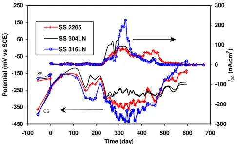
Active CS Coupled with Passive CS or SS. The galvanic coupling test was also performed in concrete specimens. Figure 5 shows the galvanic coupling potential and Igc
-450 -350 -250 -150 -50 50 150 250 -100 0 100 200 300 400 500 600 700 Time (day) Potential (mV vs SCE) -300 -200 -100 0 100 200 300 Igc (nA/cm 2 ) SS 2205 SS 304LN SS 316LN SS CS
Figure 5. Galvanic coupling potentials and Igc of corroding CS (in concrete with 1.5
wt% Cl-) coupled with SS (in the concrete with 3.5 wt% Cl-).
of active CS coupled with SS. CS rebars were cast in the concrete containing 1.5 wt% chloride ions while SS rebars were embedded in concrete containing 3.5 wt% chloride ions. Before coupling the two rebars, the open circuit potential of CS was more negative than that of SS (refer to the potentials before time 0). After the connection of the two rebars, the coupling potential varied between –0.08 V and –0.3 V over 220 days. During this time, the galvanic coupling current densities were relatively low (around a few nA/cm2), indicating no considerable galvanic coupling current. It was very likely that CS embedded in the concrete containing 1.5 wt% chloride was in an initial corrosion development stage. After the 220 days, the high temperature of the environmental chamber was changed from 45oC to 50oC. The coupling potential shifted towards more negative values at about –0.25 V to –0.45 V, while the Igc increased significantly to
around 80, 120 and 226 nA/cm2 for SS 2205, 304LN and 316LN, respectively. Igc then
decreased gradually to very low values (approaching 0) for all three SS due to increased contact resistance between CS and the concrete resulting from severe cracking of the concrete near the corroding CS rebars.
The galvanic coupling potential and Igc measured from active CS coupled with the
passive CS is shown in Figure 6. Two CS were embedded in the concrete specimens: one in chloride-free concrete and the other in concrete containing 1.5 wt% chloride ions. In the first 220 days, the coupling potential varied around –0.15 V, and the coupling current remained very low (< 20 nA/cm2). After 275 days, the coupling potential dropped to –0.4 V, while the coupling current increased rapidly to 850 nA/cm2, then decreased to a very low value, close to 0 nA/cm2, due to concrete cracking around the active rebars. It was therefore shown that Igc between active and passive CS was much higher than that
between active CS and SS, even when the SS was in concrete containing 3.5 wt% chloride ions.
This result is in good agreement with that obtained in the saturated Ca(OH)2 solution in the electrochemical cell. This proves that when SS reinforcing bars are coupled with corroding CS bars, Igc is much lower (less than 226 nA/cm2) than that observed when
passive and active CS rebars are coupled (about 850 nA/cm2). Therefore, replacing CS reinforcement with SS would not increase the risk of corrosion to the CS reinforcement.
-500 -400 -300 -200 -100 0 100 200 300 400 -100 100 300 500 700 Time (day) Pot e nt ia l ( mV v s SCE) -800 -600 -400 -200 0 200 400 600 800 1000 Igc (nA/cm 2 )
Figure 6. Galvanic coupling potentials and Igc of corroding CS (in concrete with 1.5 wt%
Cl-) coupled with the passive CS (in concrete with 0% Cl-).
It was also found that, unlike the measurement in the electrochemical cell, the galvanic coupling current in the concrete did not reach its stable value shortly after coupling. The current remained very low over more than 200 days before finally increasing. This is due to the fact that the CS used as an active electrode in the electrochemical cell was already substantially corroded before the experiment, and its corrosion potential was stable at around –0.55 V to –0.60 V. When this electrode was coupled with passive CS or SS, the observed galvanic coupling behavior was determined by the cathodic reduction reaction on passive CS or SS. However CS used in concrete specimens was corrosion free before it was cast in the concrete specimens. During the first 200 days, the corrosion gradually developed on the CS when exposed to 1.5 wt% chloride ions in concrete subjected to the high humidity and temperature cycling.
Figure 7 shows the photos of the concrete specimens in which the Active CS (in concrete containing 1.5 wt% chloride ions) was coupled with different types of SS (in concrete with 3.5 wt% chloride ions) or with passive CS (in concrete containing 0% chloride ions). The photos were taken at the end of the two-year testing time. It can be seen that with concrete containing 3.5 wt% chloride ions, all concrete specimens with SS were in good condition, while those with CS were severely cracked. This cracking is a direct consequence of the severe corrosion of CS reinforcement that occurs in the presence of 1.5 wt% chloride ions. The additional corrosion induced by the galvanic coupling was limited, especially in the case of coupling with SS as discussed earlier.
Passive CS Coupled with SS. The galvanic coupling potentials and Igc on specimens
in which the passive CS was coupled with different types of SS are shown in Figure 8. The CS was in chloride free concrete, while the SS alloys were in concrete containing 3.5 wt% chloride ions. These conditions were designed to simulate a situation where SS would be incorporated into areas of aggressive salt attack. Figure 8 shows that the corrosion potentials of CS and SS were between –0.17 V to –0.2 V before the galvanic coupling and varied at around –0.1 V to –0.2 V after galvanic coupling. Igc varied within
Corroding CS (1.5 wt% Cl-) coupled with passive CS (0% Cl-)
Corroding CS (1.5 wt% Cl-) coupled with SS (3.5 wt% Cl-)
Figure 7. Photos of concrete specimens in which the corroding CS (in concrete containing 1.5 wt% Cl-) was coupled with passive CS (in concrete with 0% Cl-) or SS (in concrete containing 3.5 wt% Cl-). Severe concrete cracking can be observed around the corroding CS. -400 -300 -200 -100 0 -100 100 300 500 700 Time (day) Pot e nt ia l ( mV v s SCE) -1.0 -0.5 0.0 0.5 1.0 1.5 2.0 Igc (nA/cm 2 ) SS 2205 SS 304LN SS 316 LN
Figure 8. Galvanic coupling potential and Igc of passive CS (embedded in concrete with
0% Cl-) coupled with SS (embedded in concrete with 3.5 wt% Cl-).
The results obtained from the concrete specimens agreed closely with those found in the electrochemical cell. When CS rebars are in a passive condition, coupling these rebars with SS rebars in concrete will not initiate the corrosion on passive CS since Igc was less
than 1 nA/cm2 even when the SS was exposed to 3.5 wt% chloride ions in concrete. The results from two CS rebars embedded in chloride-free concrete are shown in Figure 9. When both CS rebars are in the passive condition, no sign of corrosion was observed. The galvanic coupling potential changed progressively from –0.13 V to +0.05 V and its
Igc was less than 0.15 nA/cm2.
Figure 10 shows photos of the concrete specimens in which the passive CS was coupled with different types of SS (in concrete 3.5 wt% chloride ions). These specimens were kept in the environmental chamber at 80% RH and cycled between 25oC and 45oC
for almost two years. All the concrete specimens were observed to be in good condition; no cracking on either side of the specimens was found.
-200 -100 0 100 200 -100 100 300 500 700 Time (day) Pot e nt ia l ( mV v s SCE) -0.16 -0.12 -0.08 -0.04 0.00 0.04 0.08 0.12 0.16 Igc (nA/cm 2 )
Figure 9. Galvanic coupling potential and Igc of passive CS (in concrete with 0% Cl-)
coupled with passive CS (in the concrete with 0% Cl-).
Figure 10. Photos of concrete specimens in which the passive CS (in concrete with 0% Cl-) was coupled with different types of SS (in concrete with 3.5 wt% chloride ions). No cracks can be observed in the concrete specimens.
The above results clearly indicate that in a situation where no chloride ions are present, the CS rebars remained in a passive condition and can last for a very long time without initiating corrosion, even when coupled with stainless steel in the presence of 3.5 wt% chloride ions. However, the rebars corrode very easily when chloride ions at the CS reinforcement surface reach or exceed the corrosion threshold level. The value of Igc (<
0.8 nA/cm2) induced by coupling SS with passive CS would not initiate the corrosion on CS reinforcement in chloride-free concrete. Since the Igc values obtained from coupling
passive CS with passive CS or SS are all much lower than 1 nA/cm2, the risk of initiation of corrosion of passive CS is very low.
Conclusions
• The galvanic coupling of stainless steel (SS) and carbon steel (CS) in the saturated Ca(OH)2 will not increase the corrosion risk of CS even when these steels are in direct contact (electrically connected). In fact, the slight increase in corrosion rate of CS due to galvanic coupling of SS and corroded CS was less than that for the combination of non-corroded CS and corroded CS. Stainless steel, with its ability to resist chloride-induced corrosion, can be used in areas that are vulnerable to chloride ingress.
• The galvanic coupling process is dominated by the cathodic reduction reaction on passive CS or SS when these steels are coupled with a corroding CS in a saturated Ca(OH)2 solution. The cathodic reduction current density on SS is significantly lower than passive CS, leading to a much lower galvanic coupling current density (Igc)
induced by SS when compared to passive CS.
• The galvanic current density can decrease significantly with an increase in the resistance of the salt bridge. It implies that the galvanic current density will also decrease with an increase in the concrete resistivity.
• Galvanic coupling tests between passive CS and SS show that Igc was around
1 nA/cm2 for all three types of SS, well below the long-term maintenance-free current density for CS even when SS was in the solution containing 3 wt% chloride ions. Therefore galvanic coupling of passive CS and SS will not initiate corrosion on passive CS.
• The galvanic coupling tests carried out in concrete specimens confirmed the laboratory experimental results obtained in electrochemical cells. When SS reinforcing bars were coupled with passive CS bars, the value of Igc (<1 nA/cm2) was
well below 10 nA/cm2 and did not initiate corrosion of the CS reinforcement in chloride-free concrete. When SS reinforcing bars were coupled with corroding CS bars, Igc was much lower than in the coupling between passive and corroding CS
reinforcements and did not increase the risk of CS corrosion. Therefore, the judicious use of stainless steel in the high-risk areas of a concrete structure would be an option for preventing corrosion and thus extending the service life of concrete structures.
Acknowledgments
Grateful acknowledgment is made to The Nickel Institute (previously the Nickel Development Institute), Alberta Transportation, The City of Ottawa, The Ministry of Transportation of Quebec and Valbruna Canada Ltd for their contributions and support for this research project. Thanks are also due to Bruce Baldock, Glendon Pye, Gordon Chan and Bob Myers of IRC/NRC for their help with the experimental research work.
References
1. H. A. Webster, COR-97-7810-N, CORRENG Consulting Service Inc., Downsview, Ontario, (1997).
2. P. J. Seibert, M.Sc Thesis, Queen's University, Kingston, Ontario, Canada (1998).
3. A. Knudsen, F. M. Jensen, O. Klinghoffer and T. Skovsgaard, International Conference on Corrosion and Rehabilitation of Reinforced Concrete Structures, p. 15, Orlando, Florida, (1998).
4. A. Knudsen, T. Skovsgaard, Concrete Engineering, 5(3), 59 (2001). 5. O. Klinghoffer, T. Frolund, B. Kofoed, A. Knudsen, F. M. Jensen and T.
Skovsgaard, Corrosion of reinforcement in concrete: corrosion mechanisms and corrosion protection J. Mietz, R. Polder and B. Elsener, Editors, p. 121, London, (2000).
6. L. Bertolini, M. Gastaldi, T. Pastore, M. P. Pedeferri, P. Pedeferri, International Conference on Corrosion and Rehabilitation of Reinforced Concrete Structures, p. 13, Orlando, Florida, (1998).
7. L. Bertolini and P. Pedeferri, Corrosion Review, 20, 129 (2002).
8. B. Hope, Final report of MTO special project Q900076, ISBN 0-7794-0479-3, MI-181, Feb. (2001).
9. M. Vukovic, Corrosion Science, 37, 111 (1994).
10. P. Langford and J. Broomfield, Construction Repair, 1, No.2, p. 32, Palladian Pubs., May (1987).
11. K. C. Clear, Concrete International, 5, 58 (1992).
12. S. Erodgdu, T. W. Bremner, Transportation Research circular, 403, 5 (1993). 13. S. Y. Qian, H. Dumont and B. E. Conway, J. Applied Electrochemistry, 27, 1245