A Basis for Magnet Improvements in the U.S. Fusion Magnet Program Joel H. Schultz, Joseph V. Minervini, Richard J. Thome
April 21, 1999
M.I.T. Plasma Science and Fusion Center Report PSFC/RR-99-6
The following is a strategic vision for magnet development, focused on the goal of improving the cost and size of superconducting and normal magnets for the magnet and inertial fusion programs. This
program vision is an attempt to be responsive to the request that a development program must be able to define quantitatively the improvements in benefits and cost/benefits to our specific subsystem. At this preliminary stage, the vision statement has not yet been matched to budget, schedule, or available resources. Neither has it been correlated to a separate vision and program of improvements in analysis techniques. However, in its defense, it is - to the best of our knowledge - the first time that anyone
worldwide, in either the fusion or HEP programs, has attempted to lay out a complete statement of how to improve magnet systems with quantitative goals. Due to the absence of previous visions, this must be considered preliminary, but will henceforth be a "living" document to be continually refined and expanded. I. Overview
The United States should be developing magnet technologies that are specifically focused on the needs of the magnetic and inertial fusion programs that will substantially lower the cost of fusion power. There are primarily two ways in which a magnet technology can lower the cost of fusion: 1) by lowering the cost of the magnets themselves and 2) by reducing the size of the magnet systems, so that the cost of other fusion reactor subsystems may be reduced. That said, the normalized goodness parameter for a magnet system isn't totally clear. For instance, one could also argue that the primary virtue of a magnet is to produce a high magnetic field, since fusion power is proportional to B4. Another virtue of a good magnet system design is the ability to absorb high nuclear flux and fluence in order to reduce the size of the neutron shield protecting the magnet system and consequently the machine as a whole. Nevertheless, in order to create a manageable and affordable program, one has to choose the goodness parameters that are the most likely to make a difference and these are:
1) The volume-specific stored energy (J/m3)
V
Wm
=
α
2) The cost-specific stored energy (J/$)
$
m W
=
γ
3) The entropy-specific refrigeration load
e ref P P = δ
We maintain that maximizing α and γ, i.e. minimizing the specific cost and volume, should simultaneously develop the technologies needed for high-field. Maximizing δ is done by minimizing the wall power needed to remove a given refrigeration load. The most exciting method of maximizing δ is through the use of high-temperature superconductors.
The clearest way of ensuring that a magnet technology will simultaneously improve α,γ,and δ is to identify the goodness factors for each of the magnet components individually. In this "0-rev"vision, we propose major improvements that can be made in the following components:
(A) Superconductor (B) Stabilizer (C) Structure
(Ca) Conductor/Structure (D) Insulation
(E) Thermal Isolation (F) Joints
(G) Leads
(H) Quench Detection and Instrumentation (I) Isolators and Feedthroughs
Two more highly important components are not considered, but are left as placemarks for a future revision: (J) Field Errors and Tolerances
(K) Refrigeration
If important quantitative and achievable goals can be realized for all of these components individually, it should be possible to reduce the cost of fusion itself.
As discussed above, for most fusion applications, specific volume α is more important than specific mass, since the majority of applications are constrained more by space than by the floor bearing strength. However, magnet mass is frequently tabulated in the published literature, volume almost never. Another difficulty in pinning down specific mass or volume is that it is sometimes unclear whether tables include cold mass only, gravity supports, and/or the cryostat. With those caveats, we have attempted to tabulate the mass of efficiencies of several superconducting and normal magnet systems in Table I-1:
I-1 Mass Efficiencies of Superconducting and Normal Magnets
Magnet Stored Energy Mass Mass/Energy
(MJ) (tonnes) (kg/kJ) Ignitor TF 1309 96 (magnet) 436.8 (magnet+clamps) 0.0730.334 TFTR, TF 1366 580 0.425 PLT, TF 251 98 0.78 PDX, TF 182 73 0.401 ATC, TF 16.7 26 1.56 Alcator A, TF 24 5.8 0.335 Alcator C, TF 95 17.7 0.372 Ormak, TF 4.5 10 2.2 ISX-A, TF 19.4 12.0 0.618 ISX-B, TF 13.5 12.0 0.889 JET, TF 940 380 0.404 Zephyr, TF 1200 300 0.25 LCP 650 290 0.446 MFTF 409 341 0.834 Tore Supra 640 206 0.322 NMR Solenoid 0.4 0.082 0.205 CS Model Coil 650 150 0.231 FED 16300 4040 0.248 STARFIRE 50000 6000 0.12 WITAMIR 60,300 8,358 0.139 NUWMAK 35,700 1,540 0.043 UWMAK III 117,000 6,564 0.056 UWMAK II 233,000 25,508 0.109 UWMAK I 216,000 23,800 0.11
It is very striking how much less efficient the actual magnet systems are than the imaginary ones. The masses of paper study magnets may have to be completely discounted. However, there is a clear trend that paper studies of visionary systems to be built in the distant future weigh the least, while the masses increase from conceptual to preliminary to final design. Therefore, we might hope that, for example, the
ITER EDA or IGNITOR designs might be relatively accurate. We are not sure what the world's record is for a real magnet. Many magnet systems don't report mass or energy after magnet operation has begun It appears that, of real magnets, the best cryocooled magnet reported here is 0.335 g/J, while the best superconducting magnet is 0.205 g/J. These numbers can be compared with those of ITER and TPX, tabulated several years ago, during the TPX project, in Table I-2:
Table I-2
Mass Efficiencies of ITER and TPX
Coil System Stored Energy Mass Mass/Energy
(GJ) (tonnes) (g/J) ITER CDA TF 40.7 6,960 +1500, OOP structure 0.209 PF 18.7 ITER EDA TF 108 11,100 (with BC) +5000, OOP structure 0.148 PF 25.3 3069 0.121 TF+PF 133.3 19,000 0.143 TPX TF 1.05 138.6 (structure) 51.1 (windings) 0.181 PF 0.113 39.0 (windings) 9.0 (structure) 0.425 TF+PF 1.163 237.1 0.204
Here it appears that most of the coils should be in the range of 0.121-0.21 g/J. The analytical resources applied to ITER were very formidable, but since none of the coils were built, the estimates could still be optimistic.
A possible integrated coil project, discussed at the end of this memorandum, might be to build a coil system with a specific mass of 0.1-02 g/J (or 0.05-0.1 g/J for aluminum magnets), since it appears that this hasn't been done yet.
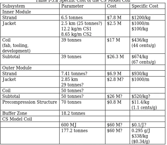
Reported costs are probably even more difficult to interpret than reported mass efficiencies, because of differences in methods of accounting. Some reported values of cost and specific cost are shown in Table I-3.a-d.
Table I-3.a Specific Cost of the CS Model Coil
Subsystem Parameter Cost Specific Cost
Inner Module Strand 6.5 tonnes $7.8 M $1200/kg Jacket 2.5 km (25 tonnes?) 12.2 kg/m CS1 8.65 kg/m CS2 $2.5 M $1000/m $100/kg Coil (fab, tooling, development) 39 tonnes $17 M $436/kg (44 cents/g) Subtotal 39 tonnes $26.3 M $674/kg (67 cents/g) Outer Module Strand 7.41 tonnes? $6.9 M $930/kg Jacket 2.85 km 29 tonnes? $2.8 M? $1000/m Coil 50 tonnes? Subtotal 50 tonnes? $26 M? $520/kg?
Precompression Structure 70 tonnes $0.8 M $11.4/kg (1.1 cents/g)
Buffer Zone 18.2 tonnes
CS Model Coil
600 MJ $60 M? $0.1/J?
177.2 tonnes $60 M? 0.295 g/J
$338/kg ($0.34/g)
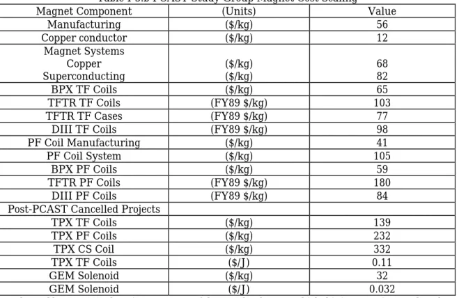
A 1995 interpretation of magnet costs by the PCAST Study Group1used the following scaling rules in its derivation of unit cost scalings. A later study added the cost of the TPX coils at the time of the project cancellation:
91-Table I-3.b PCAST Study Group Magnet Cost Scaling
Magnet Component (Units) Value
Manufacturing ($/kg) 56 Copper conductor ($/kg) 12 Magnet Systems Copper Superconducting ($/kg)($/kg) 6882 BPX TF Coils ($/kg) 65 TFTR TF Coils (FY89 $/kg) 103 TFTR TF Cases (FY89 $/kg) 77
DIII TF Coils (FY89 $/kg) 98
PF Coil Manufacturing ($/kg) 41
PF Coil System ($/kg) 105
BPX PF Coils ($/kg) 59
TFTR PF Coils (FY89 $/kg) 180
DIII PF Coils (FY89 $/kg) 84
Post-PCAST Cancelled Projects
TPX TF Coils ($/kg) 139 TPX PF Coils ($/kg) 232 TPX CS Coil ($/kg) 332 TPX TF Coils ($/J) 0.11 GEM Solenoid ($/kg) 32 GEM Solenoid ($/J) 0.032
We have not been able to recover the primary sources of the cost data base on which this intepretation was based. Since the cost of superconducting magnets is frequently confused by other issues, it should also be relevant to try to compare the numbers in the PCAST study with those of commercial magnets. The only large commercial use of superconducting magnets is that of Magnetic Resonance Imaging dipoles, with or without high field homogeneity requirements. According to unreferenceable sources, the cost of a
commercial MRI magnet with a typical specification of 2 T on axis, 3-4 T Bmax at the magnet, a 1 m bore, and a length of 2 m would have a stored energy of 4.0 MJ. The fabrication cost for a persistent mode magnet would be ~ $200 k and the sale cost would be $350 k. If the field homogeneity requirements were removed, the cost to the vendor would go down to $180 k. Using an "optimized" sale cost of $300 k for a low field homogeneity system, the specific cost would be $75/kJ or 7.5 cents/J.
A related field of considerable interest is the recent attempt to commercialized large Superconducting Energy Management Systems (SEMS), because the $/J is the single most critical
parameter for this application. We would suspect that a well-designed SEMS system would always have a better specific cost than the best fusion system, because it is far less topologically constrained and has no nuclear radiation. Two large SMES systems have been designed and costed in the past two years by BWXT. The first was an 1800 MJ system to be installed in Anchorage, Alaska. This project was cancelled, because of unfavorable cost/benefit analyses. The comparison was with gas turbines. If the magnet system had been compared to fusion magnets, it would have been a world-record breaker. As of April 1997, the entire 1800 MJ x 31.5 MVA SMES system (magnet, refrigerator, and power supply) was costed at $18 M ($0.01/J, $0.57/W). Some of the funding from the Anchorage project was transferred to a SMES project in Kentucky, costed at 30 M$ and 16 M$ for the magnet in a 100 MJ system. The specific cost is then $0.16/J. The cost is driven up significantly by the fact that it must be interfaced with an existing 25 kV bus. A summary of the specific cost of large commercial systems is shown in Table I-3.c
Table I-3.c Specific Costs of Large Commercial Superconducting Magnets
System Status Stored Energy Cold Mass Cost $/kg $/J
(MJ) (tonne) (M$) ($/kg) ($/J) MRI Commercial 4.0 0.35 0.075 SMES/Anchorage Demo/ Cancelled 1800 690 18 26 0.01 ($0.57/W) SMES/KY Demo/ Final Design 100 30 (system) 16 (magnet) 0.3 0.16
Finally, the costs of the surveyed magnets should be compared to the costs estimated for ITER magnets. The ITER magnet costs are arbitrarily recosted by multiplying by 10/6, solely on the overall multiplier between system costing in 1989 dollars ($6 B) and estimates that the actual cost would be $10 B.
Table I-3.d Specific Costs of the ITER Magnets ITER System Stored Energy Cost $/J (1989) $/J (1999)
(GJ) (M$) ($/J) ($/J)
TF 97.5 1244 0.0128 0.0213
CS 263
PF 25 (PF+CS) 222 0.0194 0.0323
These numbers are taken from the calibration column of my spreadsheet. I wasn't able to find the official numbers for ITER (but my spreadsheet adds up to $6 B.) We should probably find the official numbers before going further.
However, I note the obvious. ITER planned on building large magnet systems for 1-2 cents/J, which can be reinterpreted as 2-3 cents/J in inflated dollars. ITER Model Coils apparently cost 10 cents/J. The estimated cost of the TPX TF system, (a 1.1 GJ magnet system with Nb3Sn at only 8.5 T) by the end of Preliminary Design was also about 10 cents/J. Since no design improvements could be made between the Model Coils and ITER, the implication is that economies of scale alone would improve the specific cost by a factor of 3-10.
If the ITER costs were indeed aggressive, then the purpose of a successful development program that cuts the cost of magnets in half or in a third would be to validate the ITER costing, not improve upon it.
Because of the need to relate integrated magnet programs to subsystem programs, quantitative discussion of magnet system goals is postponed until the end of this memorandum.
A. Superconductor A.1 Introduction
Significant progress has been made in superconductors in the past 20 years, much of it funded or in support of the magnetic fusion program. The critical current densities of NbTi and Nb3Sn have improved at rates approximating 7 %/year. Recent developments in Nb3Sn have produced a new strand, being used both the fusion and high energy physics program, with about 60 % better current density than the ITER HP-I strand and 180 % better engineering current density. A new variant of NbTi, called the Artificial Pinning Center conductor, has been developed, with the promise of providing better performance than NbTi at fields below 5 T at half the price. A new A15 material, Nb3Al, has shown the possibility of
slightly better performance than Nb3Sn with a strain-sensitivity that may be sufficiently reduced to permit react-and-wind fabrication at high fields. Finally, high-temperature superconductors have begun to be commercialized. They are now the conductor of choice for leads below 15 kA and may also be the best superconductor for small, low-field magnets or smaller, high-field inserts.
A.2 State-of-the-Art
State-of-the-art performance of existing superconductors has tended to be expressed at three operating points with historic significance, but which do not necessarily represent the most relevant range of applications for magnetic fusion.
Table A-I: Achieved Values of Jc and Jeff, Present Superconductors Conductor B(T) T(K) Jc (A/mm2) Qh (mJ/cc +/- 3 T) NbTi 5 4.2 2700 Nb3Sn (HP-I) 12 4.2 700 600 Nb3Sn (HP-II) 12 4.2 550 200 High Tc 0 77 700 Jeff (A/mm2) NbTi 5 4.2 1,200 Nb3Sn (HP-I) 12 4.2 300 600 Nb3Sn (HP-II) 12 4.2 275 200 High Tc 0 77 210
Two near-term fusion projects, LDX and KSTAR are attempting to extend the performance of Nb3Sn from that already achieved for ITER. These near-term goals are shown in Table II:
Table A-II: Near-Term Strand-Development Goals
Conductor B(T) T(K) Jc (A/mm2) Qh (mJ/cc +/- 3 T) HP-III (KSTAR) 12 4.2 850 200 LDX 12 4.2 1,125 600 Jeff (A/mm2) HP-III (KSTAR) 5 4.2 340 LDX 12 4.2 700 600
A single prototype billet and heat has demonstrated the Jc, Jeff, and Qh performance mandated for both the LDX and the HP-III strand. 1,000 kg of HP-III strand and 100 kg of LDX strand are on order.
A.3 Goals
Based on conversations with vendors, we believe that the following goals can be met simultaneously within the next five years:
Table A-III: Five-Year Strand goals
Conductor B(T) T(K) Jc (A/mm2) Qh (mJ/cc +/- 3 T) Nb3Sn 12 4.2 1,500 600 NbTi/APC 5 4.2 3,600 High Tc 0 77 140 Jeff (A/mm2) Nb3Sn 12 4.2 1,100 600 NbTi/APC 5 4.2 1,800 High Tc 0 77 250
Adding some cost goals to the performance goals below, the improvements in strand technology to be achieved are summarized in Table IV:
Table A-IV: Improvements in Strand Technology, Next Five Years Conductor Jc
(A/mm2)
Improvement Jeff(A/mm2
) Improvement $/kg, now $/kg, 5 years Improvement Improvement $/kA-m Best NbTi/APC 3,600 33 % 1,800 50 100 50 2:1 2.7:1 Nb3Sn 1,500 2.1:1 1,100 3.6:1 800 500 1.6:1 5.8:1 High Tc 140 2:1 63 3:1 2,000 1,000 2:1 6:1
No individual purchase need be greater than a 50 kg billet. Therefore, it would be difficult to really get an accurate assessment of improvements in cost during this period. Improvements in performance will be easier to evaluate, since a 50 kg billet can provide adequate strand length for even the largest coil between joints. Thus, the performance of prototype billets will always be relevant to production, since there is always the option of using smaller billets, if scale-up is difficult.
Assessment of improvements in cost would be made by using prototype billet costs as a reality check and, hopefully, by the use of improved strand in production-scale purchases, during this period, such as KSTAR.
The improvement of Jeff in superconducting strands is the single most important goal of the next five years for the following reasons: 1) Nb3Sn strand costs have been a significant fraction of the total magnet costs for both fusion and HEP magnets, 2) strand fabrication has usually been on the machine critical path, 3) purchasing and testing prototype billets is relatively inexpensive and almost always leads directly to conductor improvement, and 4) the combined technique of using Superconductor-Laced Copper Conductor (SLCC) cables, described below, is a nearly certain way of achieving another factor of two reduction in strand weight and cost. Here is one scenario for the consequences of success. The improvement of 2.1:1 in Jc would reduce the weight of Nb3Sn in ITER from 800 tonnes to 380 tonnes, combined with success in developing SLCC, the weight would be reduced to 220 tonnes. If design efforts in ITER-RC abroad ever get as far as the Advanced Tokamak Burning Plasma Experiment (ATBX) and reduce the size of the coils by a factor of two, the weight would be reduced to 110 tonnes. At one extreme, it was feared that Nb3Sn strand in ITER might stubbornly remain at $1,000/kg, requiring a Nb3Sn strand purchase of $800 M. If performance improvements can be combined with the specific cost improvement to $500/kg postulated by ITER, the cost of Nb3Sn strand for an ITER-RC would be only $55 M. With a focused strand development program, we regard this as doable.
A.4 Plan
The improvement of Jc in a strand is relatively straightforward. At least two prototype billets should be purchased each year, and their critical current, critical temperature, and hysteresis loss should be measured. Despite their somewhat arbitrary nature, 5 T/4.2 K, 12 T/4.2 K, 0 T/77 K should probably be maintained as the reference fields and temperatures used for performance specification of low-field, high-field, and high temperature strand performance, during this period.
The improvement of Jeff is more complicated and can be subdivided into four parts. The first, already discussed, is simply to improve Jc with its associated improvement of Jeff, all other parameters being equal. The second is to decrease the copper/noncopper ratio of the strands. The LDX/D20 preprototype strand demonstrated a copper fraction of only 0.3, while the LDX production strand will have a copper fraction of 0.37. The third is to develop finer strands for a price that is competitive with thicker strands. S. Pourrahimi, working with Supercon, has demonstrated bronze-method strands with a diameter less than 0.1 mm and no stabilizer that meet HP-I specifications. Thus, they would not only have an effective current density that is 2.5 times higher than an HP-I strand with a copper/noncopper ratio of 1.5:1, but the cable might be able to operate at up to twice the overall stablizer current density, as discussed below, because it would have four times the wetted perimeter of a cable based on 0.8 mm strand. Finally, the effect on ramp-rate limitations of high Jeff cables has to be quantified. Ramp-rate limits will undoubtedly be more restrictive when stabilizing copper is moved from the composite strand to adjacent strands. Part of this degradation can be restored by the use of finer strands. The purpose of an R&D and theory program is to identify the design regimes in which the effect on conductor cost is first-order, while any negative effect on ramp-rate limitations is only second order. In order to do this, the most important requirement is to continue the series of ramp-rate limitation tests that were conducted on subcables for the DPC and TPX programs. These tests were terminated with the cancellation of TPX and never revived, because the pulsed magnets used to conduct the tests were rendered nonoperational by the closing of the Francis Bitter National Magnet Laboratory. They have not been duplicated by the National High Field Magnet Laboratory. A new superconducting pulsed solenoid should be built as the standard reference tool for testing ramp-rate limitations. This same magnet can also be used for testing quench detectors, all other pulsed field and cryogenic instrumentation, electrical isolators, and feedthroughs.
The plan for improving Jeff includes the following elements: 1) Build a 10 T x 2.5 T/s x 25 cm warm bore pulsed magnet
2) Purchase and test at least one high Jeff prototype billet/year, with not only high Jc, but also low copper fraction. If the strand performs well, a 27 strand subcable should be fabricated and its ramp-rate limitations measured, including the size and number of precursor/recovery "blips."
3) Purchase and test at least one high Jeff, low diameter strand, every two years. If the strand performs well, a 5 kA, 135 strand subcable should be fabricated and its ramp-rate limtiations measured.
A stabilizer matrix is required in parallel with superconducting material for several reasons, including the
protection of the magnet, if it should quench; the stability (recovery) of the conductor against disturbances, and the ability to draw or extrude the superconducting wire to its final size. In most, perhaps all, of the magnets contemplated for the fusion program, the size of a cable or conductor is determined more by the current density limits on the matrix than by the superconductor. Methods that can be used to increase the current density in the stabilizer matrix include the use of internal heater wires, finer strands, faster quench detection, and improvements in conductor fabrication techniques.
B.2 State-of-the-Art
The state-of-the-art can perhaps be best expressed through the single parameter of the stabilizer current density at the beginning of quench (A/mm2). This can be misleading. For example, the reason that the current density is less than half that of TPX or KSTAR is that there is 100 times as much stored energy in the coil system. If the current density were increased to > 200 A/mm2, the terminal voltages would either increase to 40 kV or a different type of quench method, such as internal heaters, would have to be developed. This is, in fact, what we recommend, since the approach of this program is that every component's performance must be improved across-the-board. State-of-the-art performance in stabilizer current density is shown in Table B-I.
Table B-I State-of-the-Art Performance in Stabilizer Current Density
Magnet Icond Acu Jcu t@J2t=2.9x10⁵ (A/mm2)2-s
(kA) (mm2) (A/ mm2) (s) Tore Supra 1.4 9.9 141 14.4 T-15 Nominal Extended 3.8 5.6 80 48.75 70.0 120.3 58.4 US-DPC 20 kA (1st quench) 32.kA (highest Iramp)
20 32 58.1 344.5 551 2.41 0.942 ITER TF HF TF MF TF LF 46 46 46 387 403.7 418.2 119 114 110 20.2 22.0 23.6 TPX TF CS PF Outer 33 200 219 160 7.15 5.96 11.2 HEP Dipoles Low Jcu High Jcu 800 1400 High Tc Superconductors 0.030 Aag=0.33 90 B.3 Goals
The goals of a five-year program to improve stabilizer current density should be separated into three categories: 1) CICC-low temperature superconductors, 2) Dipole/quadrupole (Rutherford cable)-low temperature superconductors, and 3) High-temperature superconductors. Based on analysis, we propose the following goals:
Table B.3 Stabilizer current density goals
Conductor Type Units Goal
CICC (A/mm2) 350
Quadrupole (Rutherford Cable) (A/mm2) 1800 High-temperature superconductor (A/mm2) 180
The goals for CICC and Rutherford cable imply the development and use of internal dump by electric heaters. The goal for high-temperature superconductor implies the use of passive self-protection without quench.
B.4 Plan B.4.i. CICC
The current density of an externally dumped magnet can only be increased to the first order by increasing the dump voltage or decreasing the dump energy by subdividing. Since there are obvious fundamental limitations to either approach, the primary strategy for improving CICC current density will be to adopt a variant on the HEP method of using heater blankets and cowind heater wires along with the cable. These heater wires should also be designed to be used as high-sensitivity quench detectors, as discussed below in Section I. In the ATBX design, we used simple hand calculations to demonstrate that the peak-average ratio of local energy deposition could be held to 10:1, using heaters with 1/100th the power rating requirements of external dump circuits. Therefore, the triple win of this concept is to 1) reduce the cost of interrupter/dump circuits, 2) increase the current density in the copper and 3) provide a "free" quench detection system at the same time.
The first step would be to develop the numerical tools for analyzing quenches whose propagation is enhanced by internal heaters. These tools would then be used to confirm the method's workability in ITER and ITER-RC, then to design an inexpensive demonstration experiment. Based on the experience of QUELL, a well-instrumented quench detection and propagation experiment can give very definitive confirmation of design code accuracy.
B.4.ii Quadrupole (Rutherford Cable)
The current method of installing heater blankets on the inside and outside radius of a well-contained dipole or quadrupole is probably close to the theoretical limits of magnet protectability. Nevertheless, we think that a prototype of a heavy ion fusion driver (HIFD) quadrupole should be built to push the limits, because the HIFD quadrupoles are higher current density and lower field than conventional dipoles, and thus smaller. An increase of the copper current density to 1,800 A/mm2 should be achievable, just because of the decreased thermal diffusion time. The HIFD program for IRE proposes to build a prototype quadrupole array each year for four years. The demonstration of high copper current density should be made in an early prototype array.
B.4.iii High-temperature superconductors
Doubling the current density in the stabilizer of a high-temperature superconductor should be simple from the standpoint of manufacturing and stability, because they are inherently very stable and the increase in stabilizer current-density doesn't require any additional manufacturing improvements, in superconductor fill-factor, since we had already postulated the improvements in Jc and Jeff. However, the conflict between protection and the improvement of current density is difficult to solve. High-temperature superconductors have the quintuple disadvantage that 1) they have a lower J2t integral between operating temperature and acceptable hot spot temperature by about a factor of 2 at 77 K, 2) at present the matrix material must be silver, whose J2t is not as good as copper's , 3) they can never depend on passive protection through rapid propagation of quench, since quench propagation is very slow, 4) the slow quench propagation also makes
propagation voltages low and hard to detect, and 5) they are hard to protect with heaters, because much more energy is needed to raise the high heat capacity metals to quench at high temperatures.
Operating high-temperature superconductors at low temperature solves some of these problems and is probably the design of choice in the near-future. However, a more exciting method of enhancing performance is to take advantage of the high heat capacity and low n-value of the high-temperature superconductors to make them intrinsically self-protecting. Unlike passively-protected low temperature magnets, which depend on the speed of quench diffusion through a magnet, a passively-protected high temperature magnet would depend on the high n-values to develop a resistive zone that could discharge the magnet safely without there ever being a local thermal instability (i.e. quench) in the magnet. This
phenomenon has been observed in High-Temperature magnet designers. The fusion plan would be to develop the theory and design tools necessary to calculate the regimes in which passive protection was possible. Having developed numerical tools, a demonstration magnet would be designed with a supplementary dump circuit that could straddle both regimes and demonstrate the limits. C. Structure
C.1 Introduction
Structural materials are required in order to contain the Lorentz loads of the magnetic pressure vessel, to contain pressurized helium in a CICC, especially during quench, and to contain gravitational forces (severe during an earthquake and particularly severe in Levitated Diples, during a loss-of-control
collision). Structural materials must also avoid excessive rigidity in the wrong locations, during thermal cooldown and quench heating. They must be compatible with coil winding, and, where applicable, with winding separation for insulation and with conductor heat treatment.
C.2 State-of-the-Art
The usual measures of structural goodness are the yield strength (MPa), ultimate strength (MPa), and the toughness KIC (MPa-m1/2). Frequently these parameters are more important in welds than in structural base material. The yield strength, ultimate tensile strength, and static allowables of several commonly used structural materials are shown in Table C.2-I
Table C.2-I Static Allowables of Structural Materials
Material Base/Weld T YS SUT 2/3 YS 1/2 SUT σallow Ratio
(K) (MPa) (MPa) (MPa) (MPa) (MPa)
304 LN Full Cold Worked Base 4 1558 2015 1038.7 1007.5 1007.5 1.5265
304 LN Full Cold Worked Base 300 1193 1320 795.3 660 660
304 LN HT Base 4 800 1600 533.3 800 533.333 2.667 304 LN HT Base 300 300 600 200 300 200 304 LN Weld 4 569 1703 379.3 851.5 379.333 1.942 304 LN Weld 300 293 658 195.3 329 195.333 316 LN Base 4 815 1360 543.3 680 543.333 2.7177 316 LN Base 300 300 550 200 275 200 316 LN Weld 4 720 1100 480 550 480 2.25 316 LN Weld 300 320 480 213.3 240 213.333 Incoloy 908 Base 4 1227 1892 818 946 818 1.1415 Incoloy 908 Base 300 1075 1443 716.7 721.5 716.666 Incoloy 908 Weld 4 1279 1648 852.7 824 824 1.25 Incoloy 908 Weld 300 1062 1316 708 658 658 Ti-5Al-2.5Sn Base 4 1450 1570 966.7 785 785 1.96 Ti-5Al-2.5Sn Base 300 740 800 493.3 400 400 Ti-5Al-2.5Sn Weld 4 1510 1380 1006.7 690 690 1.692 Ti-5Al-2.5Sn Weld 300 785 815 523.3 407.5 407.5 Inconel 625 Base 4 0 0 0 0 Inconel 625 Base 300 490 900 326.7 450 326.666 Inconel 625 Weld 4 0 0 0 0 Inconel 625 Weld 300 450 900 300 450 300 Inconel 718 Base 4 1300 1600 866.7 800 800 1.333 Inconel 718 Base 300 1000 1200 666.7 600 600 Inconel 718 Weld 4 900 1300 600 650 600 1.5 Inconel 718 Weld 300 600 900 400 450 400 Aluminum 6061 Base 4 360 500 240 250 240 1.5487 Aluminum 6061 Base 300 290 310 193.3 155 155 Aluminum 6061 Weld 4 260 340 173.3 170 170 1.8219 Aluminum 6061 Weld 300 140 210 93.3 105 93.3333 Aluminum 7039 Base 4 500 650 333.3 325 325 1.518 Aluminum 7039 Base 300 330 430 220 215 215 Aluminum 7039 Weld 4 260 360 173.3 180 173.333 1.2385 Aluminum 7039 Weld 300 210 350 140 175 140
1/2 Hard Copper Base 4 410 490 273.3 245 245 1.361
1/2 Hard Copper Base 300 330 360 220 180 180
Soft Copper Weld 300 70 200 46.7 100 46.6666 C.3 Goals
Inexpensive, relatively high performance 300 series steels will remain the low-cost structural materials of choice in both the short and medium term. Although very difficult, it may be possible to develop an alloy during a 5 year period with a combination of higher strength and toughness than Incoloy 908 with the same excellent strain compatibility with Nb3Sn. However, there are still several issues that remain in guaranteeing the use of the best structural materials in all fusion magnets. These include:
C.3.i) Incoloy development
C.3.i.a) Code qualification of Incoloy 908
A property data base has been developed for Incoloy 908 base metal, welds, and transition joints that has proved to be adequate for the ITER CS Model Coil. In order to use Incoloy 908 in ITER or an ITER-RC and to reduce the ultimate cost of Incoloy 908, the work should be completed in creating an adequate data base for ASTM code qualification. During the ITER program Extension of the data base for 908 still requires characterization of toughness, SAGBO, and crack growth as a function of heat treatment, as well as procedures and characteristics of joints to other materials. Incoloy 908 is relatively well characterized for the ITER heat treatment of 650 C for 200 hours. Other heat treatments of particular interest are the shorter and hotter treatments required by Nb3Al and high-temperature superconductors.
During the ITER period, advanced weld wire materials were developed at the PSFC with very low degradation of properties during prcoessing. The new weld wires were not developed in time for use in the ITER CS Model Coil. However, an adequate data base can be developed for ITER or ITER-RC. The same is true of the characterization of joints and terminations. A key issue is the guaranteed elimination of helium leakage at the joints.
The quantitative goal of complete qualification of Incoloy 908 is to generate broad acceptance of the material and reduce the specific cost by a factor of two from $40/kg to $20/kg.
C.3.i.b) SAGBO resistance in Incoloy
Fusion programs, beginning with the US-DPC magnets and concluding with the ITER CS Model Coil have developed the procedures for welding and heat treatment of Incoloy 908 so that embrittlement by Stress-Aggravated Grain Boundary Oxidation (SAGBO) does not occur. However, the risk of accident can be greatly reduced if a variation on the 908 alloy were developed with the same or even better mechanical properties, but more resistance to oxidation. Incoloy 908 can develop SAGBO at high tensile stress with an oxygen content of 0.1 ppm. Our goal is to develop an Incoloy series that is simultaneously stronger and tougher than 908 at cryogenic temperature and that resists SAGBO at any stress up to an oxygen content of at least 10 ppm, or an improvement of at least 100.
C.3.ii) Toughness of 300 series steel after heat-treatment
300-series steels such as 304LN or 316LN are less expensive and better qualified than Incoloy 908 for most applications. However, for the long heat treatments needed for Nb3Sn, they are actually less well characterized. The superiority of Incoloy 908 over 316LN is that it was designed to be compatible with Nb3Sn heat
treatments, over a broad range of temperatures and times. This is particularly important for internal tin designs, which tend to require heat treatments of 250-300 hours. For example, the toughness of Incoloy 908, KIC = 235 MPa m1/2 at 275 hr at 700 C. The toughness of 300-series base metal and welds degrades significantly, during long heat treatments. A typical curve is shown in Figure C.3.ii-1:
In order to survive the heat treatment, using 316LN, a low carbon steel, enriched with nitrogen was used. Reed and Walsh have shown that chrome carbide embrittlement can be avoided by reducing the carbon content of 316LN2. A similar, low-carbon, high-nitrogen 316LN was used by the National
High Field Magnet Laboratory in the 45 T Hybrid Nb3Sn Outsert coil. This material was designed for only a 90 hour heat treatment, and required a very low carbon content and consequently a high specific cost of $26/kg. The TPX and KSTAR Nb3Sn 's require 260 hour heat treatments: a regime where it can be seen that there is no data base at all and reason for concern that there will be severe degradation for all known 300 series steels.
The goal of a 300 series steel development program would be to characterize a 300 steel whose strength and toughness would be no worse than that of 304LN with a weld toughness of at least 250 MPa-m1/2 after a 700 C heat treatment of 260 hours and a specific cost of no more than $10/kg. C.3.iii Welds and transitions in Copper Alloy Plates
Several low-cost burning plasma experiment concepts involve the use of high-strength, high-conductivity plate materials. These might use either copper alloys with a good combination of strength and conductivity or sandwiches of a better conducting material, such as copper, and a structural material, such as steel. It has recently been suggested that the best combination of materials for a given mission might be a sandwich of copper alloys and copper. In previous designs of this sort, such as the Burning Plasma Experiment (BPX), the base beryllium copper had an allowable operating stress of ~ 430 MPa. However, the allowable stress in the welds was only ~ 175 MPa. Discussions with vendors indicate that beryllium copper plates can be welded with stress limits up to 90 % of the base metal.
The goal is to develop welding and bonding techniques, along with design analytical techniques that permit a primary membrane stress in the throat of a next-step TF magnet of at least 400 MPa with an averaged J2t of at least 8 x 10¹⁶ A2-s/m4 (double the allowable for BeCu in BPX).
C.4 Plan
Incoloy 908 welds and brazes to Monel should be characeterized until there is an adequate data base to obtain ASTM code stamp approval for use in pressure vessels.
Work should begin in developing a second-generation Incoloy with high working stress, toughness, and SAGBO resistance than Incoloy 908. The goals should include:
1) Yield stress > 1400 MPa
2) KIC after a 300 hour burn at 700 C > 300 MPa-m1/2.
3) No SAGBO at any stress at oxygen concentrations up to 10 ppm.
300 series steels should be characterized with high enough carbon contents to be economical, but with adequate resistance to heat treatments to achieve weld toughnesses of KIC > 250 MPa-m m1/2 after a 300 hour burn at 700 C. C.a Conductor/Structure
C.a.1 State-of-the-Art
In advanced, high-field normal magnets, it is necessary for the conductor to also be a strong structural material. In general, this means that the conductor should be either a high-strength alloy of copper or a copper/structure lamination, such as copper/steel. Both copper alloys and copper/steel laminates tend to lie upon a "classic" tradeoff curve between strength and conductivity. Two examples of these curves are given in Tables C.a.1 and C.a.2.
Table C.a.1 Yield Strength (ksi, MPa) vs. %IACS of Candidate Copper Alloys (coutesy I. Zatz, Princeton Plasma
Physics Laboratory)
Table C.a.2 Ultimate Strength (MPa) vs. %IACS of Candidate Copper Alloys (courtesy M. Bird, R. Walsh,
National High Field Magnet Laboratory)
Most copper alloys and copper/structure laminates follow approximately the following two equations:
3
.
13
)
%
100
(
360
=
−
+
=
YS YS YSK
IACS
K
σ
C.a.14
.
11
)
%
100
(
400
=
−
+
=
UTS UTS UTSK
IACS
K
σ
C.a.2The range of validity of these equations is approximately 70-100% IACS. Measurements of the performance of Cu-20%Ag in Japan and the National High Field Magnet Laboratory indicate that it is possible to develop plates in practical sizes that can raise KUTS from 11.4 to 23 MPa/%IACS and KYS from 13.3 to 17.4 MPa/%IACS3. A 16 T solenoid was built with this
alloy. Supercon has developed NbCu plates with similar characteristics. The disadvantages of the the more advanced alloys are (1) that they are not available in the range of sizes needed for burning plasma experiments ~ 0.5-5.0 cm x 20-50 cm or lose strength at higher thicknesses, (2) they are very expensive ($100-$300/kg), and (3) they don't have multiple vendors and the silver alloy has no domestic vendor.
C.a.2 Goal
Work with a US vendor to develop a practical copper alloy plate in sizes useful for near-term and proposed burning-plasma experiments with a value of KUTS of at least 23 MPa/%IACS and KYS from 13.3 to 17.4 MPa/%IACS from
70-95%IACS. C.a.3 Plan
Identify a US vendor willing and capable of developing the required size and capacity plates. If none, identify a foreign vendor. Prepare and test small samples of candidate alloys over range of thicknesses, test the G-function (A2
3 Y. Sakai et al, "Development of high-strength, high-conductivity Cu-Ag alloys for high-field pulsed magnet use," Appl.
s/mm4) from 30 K to 300 K, as well as resistivity and strength. Manufacture prototype plates in minimum and maximum thickness.
D. Insulation D.1 Introduction
Electrical insulation is needed to prevent leakage current and arcs due to magnet voltages during charging, discharging, and quench dump. The insulation must be able to withstand voltages that to date have gone as high as 25 kV. They must also act as a key structural element in maintaining winding pack stiffness or allowing local expansion, strain sharing, and load bearing in a conductor in plate design. Where insulators can develop tensile loads, they must have adequate shear strength to prevent tearing. In the front layers of a toroidal field magnets, insulation must also be able to withstand neutron and gamma irradiation. The ability to withstand this radiation is frequently the magnet limit that determines the thickness of the neutron shield.
D.2 State-of-the-Art
Individual components in insulation systems are frequently ranked by their compressive strength (MPa), shear strength (MPa), and dielectric strength (kV/mm). The properties of some candidate insulations are listed in Tables D.2-I-III.
Extensive insulation materials screening was done as part of the U.S. ITER Insulation Program. A report on materials screening results exists in a series of viewgraphs by Schutz of Composite Technology Development4. The results of the screening are tabulated below:
Table D.2-I Candidate VPI Resin Systems Screening Tests at 76 K Short beam shear test for apparent interlaminar shear strength
Resin Type Resin System Apparent interlaminar shear strength Coefficient of Variation
(MPa) (%) Flexibilized DGEBA CTD-101K 108 4 DGEBA Shell 826 112 113 DGEBA ER-321 84 4 DGEBA VRI-3407 64 10 Polyesterimide VRI-3308 23 5
Table D.2-II: Candidate Prepreg Resin Systems Screening Tests at 76 K Short beam shear test for apparent interlaminar shear strength
Resin Type Resin System Apparent interlaminar shear strength Coefficient of Variation
(MPa) (%)
DGEBA Epoxy SP-250 63 1
DGEBA Epoxy XP-1003 64 1
DGEBA Epoxy BASF-5216 34 2
DGEBA Epoxy LTM-12 27 1 TGDM/DGEBA Blend JDL-552 51 6 TGDM Epoxy CTD-112P 108 6 Bismaleimide CTD-200P 37 6 Polyimide CTD-320P 41 6 Polyimide AFR-700 110 3
4 J.B. Schutz, "Materials screening for ITER TF coil insulation," Proceedings of ITER Workshop on U.S. Insulation Program and OFE Base Program Review of Low-Temperature Structural Alloys," Oct 12 and 13, Hyannis, MA
Table D.2-III: Candidate VPI Resin Systems Screening Tests at 4 K and 76 K 45o Shear/Compression Strength
Resin Type Resin System Shear/Compression Strength Coefficient of Variation
(MPa) (%) 76 K Flexibilized DGEBA CTD-101K 176 2 DGEBA Shell 826 171 7 TGDM CTD-110X 137 7 4 K Flexibilized DGEBA CTD-101K 178 3 DGEBA Shell 826 177 5
Schutz's conclusions were that DGEBA epoxy systems were superior to other VPI resin systems and that TGDM epoxy systems were unsuitable for ITER. Flexibilized DGEBA (CTD-101K) and DGEBA (Shell 836) resin systems were selected for further evaluation in the ITER irradiation program. CTD-101K was ultimately selected. By contrast, Schutz concluded that TGDM and polyimide prepreg systems were superior to DGEBA, DGEBA blend, and BMI resin systems. TGDM (CTD-112P) and polyimide (AFR-700) resin systems were selected for further evaluation.
Schutz also provided a summary table of the dielectric strength of the candidate insulation systems. Table D.2-IV: Dielectric Strength at 76 K of Candidate Insulation Systems
Material Specimen Thickness Breakdown Voltage Dielectric Strength
(mm) (kV) (kV/mm)
VPI epoxy systems
CTD-101K/2 plies 6781 glass fabric 0.53 40 76
Shell 826/2 plies 6781 glass fabric 0.52 46 88
VPI epoxy systems with barrier
CTD-101K/6781 glass fabric/Kapton HA 0.55 >50 > 90
CTD-101K/6781 glass fabric/IM1498-37B Mica 0.57 >46 >82
Prepreg epoxy systems
CTD-112P/2 plies 6781 glass fabric 0.55 44 80
CTD-105P/2 plies 6781 glass fabric 0.64 34 53
JDL-552/2 plies 6781 glass fabric 0.58 30 51
CTD-1PFS/2 plies 6781 glass fabric 0.59 46 77
Prepreg epoxy systems with barrier
CTD-112P/1 ply 6781 glass fabric/IMI 498-37B 0.63 49 78
CTD-112P/1 ply 6781 glass fabric/VRI #6293 0.5 42 85
CTD-112P/1 ply 6781 glass fabric/MM #553 0.59 >48 >81
CTD-112P/2 plies 6781 glass fabric/Kapton HA 0.57 >46 >82
Prepreg polyimide systems
CTD-320/2 plies 6781 glass fabric/IMI 498-37B 0.69 >55 >79
AFR 700/2 plies 6781 glass fabric 0.50 >55 >79
Prepreg polyimide systems with barrier
AFR 700/2 plies 6781 glass fabric/Kapton HA 0.52 49 94
As with the TPX tests, reported below, all candidate insulation systems look quite good. However, the CTD-101K/6781 glass fabric/Kapton HA VPI epoxy/barrier hybrid system is an obvious first choice, since it also has good shear strength. TPX sample tests indicated that EPON 826 had higher performance than CTD 101-K, the ITER choice. Kapton was the best all-around unreinforced polyimide for high dielectric strength.
The combined mechanical and electrical limits of a potted winding pack with rectangular conduits, which does depend upon shear strength was determined by the TPX electrical insulation development program. The following table is a summary of the 3x3 conductor stack insulation model test designs. The pulsed load applied to each stack was 28 MPa on top of a clamped preload of 14 MPa. This approximately doubled the severity of the actual mechanical load on the TPX insulation. Every one of the insulation systems, with the exception of Model 65, had excellent performance and thus 1-5 are all good candidates for
any high mechanical and electrical stress magnet design. The insulation topologies studied and the results are shown in Table D.2.V.
Table D.2.V: 3x3 Conductor Insulation Systems Tested for TPX
Model Insulation System Insulation Details Corner Roving
VPI System Turn-turn withstand (kVdc) 1-CDR Baseline 2D S-glass
Double thick
TTI Satin weave wrap 3/4" x 0.1" with G-10 L-L barriers
Glass bundle - epoxy
Shell 826 10 2-Slip plane option Kapton at the conduit with
2D weave overwrap
Kapton H 0.001" with XMPI adhesive , TTI plain weave wrap 3/4"x0.008" Glass bundle - epoxy Shell 826 28-39 (post15000 cycles) 30-38 (15,000 cycles+stress to failure) 3-CDR Baseline with Araldite
2D S-glass TTI plain weave wrap 3/4" x 0.008" with G-10 L-L barriers Araldite-filled Epoxy Shell 826 22, RT 5-12 (15,000 cycles+stress to failure) 4A-Interim baseline with 3D Overwrap Kapton at conduit; 3D weave overwrap
Kapton H 0.001" w/o adhesive and 3D 1"x .014" wrap 3-D Shape Dry (16) Shell 826 28-38, RT 31-40 (15,000 cycles) 20-35 (15,000 cycles+stress to failure) 4B-Interim Baseline with 3D Overwrap Kapton at conduit;2-50 %, 0.025 mm thick Kapton, type HN (no adhesive) wraps 3D weave overwrap
Same as 4A.
1-50 %, 0.356 mm thick (thin) 3D S2 fiberglass tape overwrap
3-D Shape Tackified (16), S2 fiberglass woven preform Shell 826 26-40, RT 28-40 (15000 cycles) + (stress to failure) 5A-Hybrid Prepreg with 3-D Overwrap
Kapton interleaved with 2D glass prepreg; 3D weave overwrap
CNF Plain weave 1" x 0.007" with CTD112P prepreg & Kapton H 1"x0.007" on top with 3-D 1"x0.014" overwrap 3-D Shape Tackified CTD 101K (No mold preheat) 5B-Hybrid Prepreg with 3-D Overwrap
Kapton - interleaved with 2D glass prepreg; 3D weave overwrap Same as 5A 3-D Shape Tackified (12) Dry (4) CTD 101K (No mold preheat) 101K <23, RT 0 (15,000 cycles) 6A-3-D Cigar roll 3D weave S-2 glass
overwrap 3-D cloth 3.75" x 0.032" with 0.016" seam tabs 3-D Shape Tackified (8) Dry (8) Shell 826
6B-3-D Cigar roll 3D weave S-2 glass overwrap Same as 6A 3-D Shape Tackified (9) Dry (7) Shell 826
5 T. Antaya has argued that Option 6 was fabricated incorrectly and that the tests were irrelevant to the fundamental limits of that insulation option.
The baseline design kapton over the conduit, a 3D weave overwrap and a 3D tackified corner fill -- was confirmed as the highest performing option. However, all of the options with the exception of the cigar roll had objectively high performance. The superiority of the TPX interim baseline is that when it fails mechanically, it fails through the VPI part of the insulation, without damaging the kapton wrap, so that large through cracks don't affect electrical integrity. Option 2, the kapton slip-plane with 2D overwrap, also had this "belt-and-suspenders' advantage over the other three design options.
The intrinsic dielectric strength of the best solid organic insulations exceeds 500 kV/mm. However, in service, the electrical field in an organic insulation is unlikely to exceed 2 kV/mm. In ITER, the
maximum design electric field in the TF insulation was 5 kV/mm in 4 mm or 1.25 kV/mm. In TPX, it was 500 V/mm. The electric field in KSTAR is not known yet, but since the insulation is the same thickness as TPX' and the terminal voltages are lower, it should be below 500 V/mm.
D.3 Goals
D.3.i Higher specific performance in the insulation
The transmission line practice of allowing 2 kV/mm in an epoxy-glass system and 10 kV/mm in kapton has not yet been adopted by the fusion community. An obvious and inexpensive next-step in
reducing the volume and cost of insulation would be halve the thickness of the insulation. This can be done either by halving the number of glass fabric plies from two to 1 or by using plies of half the thickness. For rectangular, potted winding packs, the interturn resistance can be reduced from 1.6 mm to 0.8 mm. This has a second benefit of reducing the bending in the corners of the conduits, because of reduced insulation compliance. It has a third benefit of reducing the cusp area in which it is hardest to avoid resin-rich regions. In an ITER TF-like design with individual ground wraps around each conductor, insulation thickness is also useful as a cushion between the conductor and plate, during a quench, when the conductor expands from overpressure and heating.
The overall goal should be to reduce the insulation thickness by a factor of 2.5 for square conduits in winding packs and by 1.5 for conduits in plates. The goals can be restated as validating design to 1.25 kV/mm, nominal, in winding packs and to 2 kV/mm in conductor in plate.
D.3.ii Compatibility with heat treatment
The process of insulating a winding can be simplified if insulation can be applied during winding, then the winding and its insulation go through the heat treatment together. This is followed by vacuum impregnation. The cost savings in winding and insulation are counterbalanced by any damage to the insulating material or degradation during the winding and heat treatment. Significant testing has been done in Europe on different glasses and ceramics, showing that ceramics and some variants of S-glass show little degradation during heat treatment.
Another difficulty in putting the insulation through the heat treatment is the possibility of contaminating the surface of the conductor conduit with sizing or water vapor. In a famous or infamous experiment at the National High Field Magnet Laboratory, an Incoloy 908 conduit was destroyed by SAGBO, after heat treatment with its insulation. Outgassing of water from the insulation was blamed for the SAGBO, although this was never established. A specific goal would be to demonstrate the compatibility of Incoloy 908 with external insulation, either by 1) proving that water vapor was not the cause of the NHFML failure, 2) eliminating the failure mechanism by shot-peening, 3) developing an Incoloy alloy, as mentioned above with higher resistance to SAGBO, or 4) improving the desizing/baking techniques to maximize glass strength, while minimizing outgassing. The specific goal would be to demonstrate at least two orders of magnitude safety margin in water-outgassing for an insulation and Incoloy system.
The overall goal of the compatibility task would be to equal ITER and TPX performance (i.e. 1.25 kV/mm) in an insulation system that has gone through the heat treatment.
D.3.iii Radiation resistance
The improved electrical performance goals of D.3.i will be demonstrated at radiation dosages up to 109 rads in 3x3 stacks of rectangular and at radiation dosages of > 1010 rads for a circular conductor in plate. This is a factor of 10 improvement over ITER.
D.4 Plan
D.4.i Higher specific performance in the insulation
The inexpensive TPX insulated conduit stack tests will be repeated with 3x3 stacks of candidate conduit-insulation systems. In TPX, 6 sets of stacks were tested. Here, four stacks should be adequate, including halving the number of glass layers, halving the width of a glass layer, using a potentially improved material, and using a glass with better fill-factor or contraction properties, such as a 3D weave.
D.4.ii Compatibility with heat treatment
A 3x3 stack of rectangular conduit conductors and Incoloy 908 will be heat treated with a preapplied glass fiber insulation, and tested for SAGBO. If there are no signs of SAGBO, the stack will be impregnated. Dielectric stregnth before and after 20,000 mechanical cycles will be measured. Design to 1.25 kV/mm will be confirmed.
D4.iii Radiation resistance
Improvements in radiation resistance have usually been achieved by identifying and testing improved materials. At this point, it is probably most useful to test and confirm the radiation resistance of insulation systems. In particular, we have been claiming that the ITER TF insulation should be good to high radiation dosages of up to 1010 rads and beyond, because the insulation is always in compression with negligible shear. Radiation of a 2x2 cross-section of this insulation should be irradiation to 109 rads, 1010 rads and 510 rads, if affordable, and the dielectric strength, with and without mechanical load cycles should be measured. The same should be done for 3x3 stacks of rectangular conduit insulation systems, identical to those proposed for the insulation improvement experiments, described above. These should presumably degrade at lower radiations and be less appropriate for the TF plasma-side layers.
Industrial partners have proposed the development of superior insulating materials with simultaneous
improvements in insulation strength and radiation resistance. These should be supported through the fusion program or SBIR's. Whenever they become available, 2x2 and 3x3 stacks, identical in topology to those described in the previous paragraph should be fabricated and tested in order to measure the relation between improvements in material properties and insulation system performance.
E. Thermal Isolation E.1 Introduction
A superconducting magnet operates at cryogenic temperatures from 1.8 K to 80 K. The heat leak from the magnet to the outside world at room temperature must be limited. There are basically three components that isolate the magnet from the outside world: 1) the gravity supports, 2) cold-surface insulation against thermal radiation, and 3) bumpers. The bumpers are used to support off-normal loads, such as earthquakes and plasma disruptions. In the case of Levitated Dipoles, the off-normal loads also include collisions with the vacuum vessel wall.
E.2 State-of-the-Art
E.2.i Gravity supports
Heat leak through gravity supports can be limited by selecting a material with a good strength to thermal conductivity ratio, such as a G-10 column, and by making the support as long as possible. A long column remains as strong in compression as a short column, but the heat leak decreases proportionally with the length. However, many
magnet systems have space limitations and long-length also makes a support more vulnerable to off-normal loads and buckling. Most important, the longer the support column, the larger and more expensive the cryostat. Therefore, the goodness factor for a gravity support should be G=W/(M-L) (W/tonne-m), where M is the cold mass (tonne) and L is the length of the gravity support (m). The material goodness factors for four candidate materials are shown in Table E.2.i-1
Table E.2.i-1 Normalized Strength/Conductivity of Candidate Gravity Support Materials
Material σU RT k fmax Mpa W/(m-K) 104 x N/(W*m) 300 - 80 K SS-304 659 12.3 18.26 Inconel X-750 1222 12.5 33.33 G-10CR 420 0.28 511 G-11CR 461 0.28 562 80-5 SS 304 659 4.5 146 Inconel X-750 1222 5.0 244 G-10CR 420 0.165 2545 G-11CR 461 0.165 2794
The results of Table 1 shows that support of G11CR has the heat flux almost 17 times less than support of Inconel at 300 -80 K and 11.5 times less at -80 - 5 K (for the same force and cross section, same pressure and length).
The heat leak through a support structure can be made less than that of the material itself by 1) supporting the structure in tension at a shallow angle, so that the distance along the support is much greater than the distance to the cryostat wall, and 2) creating a convoluted path in compression. Convoluted paths include 1) Nested cylinders, supporting each other alternately at the top and bottom, 2) a meander, and 3) disks with punchouts. The latter are typically used in accelerator magnets where space is at an extreme premium. A typical thermal spacer is shown in Figure E.2.i-1. Recently, a "Pipetron" approach to a Very Large Hadron Collider (VLHC) has been proposed, that could have several hundred kilometers of underground cryostat and requires a very low leak design. The structural spacer proposed for the Pipetron is shown in Figure E.2.i-2.
Figure E.2.i-1 Conventional Dipole Magnet Gravity Support Figure E.2.i-2 Pipetron Gravity Support E.2.ii Bumpers
Bumpers can be considered as the series combination of a support column and two radiation surfaces. However, there cannot be any superinsulation between a bumper and the moving structure it is designed to protect. The goodness factor for a bumper is tonnes/W-m, but a collision factor has to be added. For example, if you want to protect a 1 tonne weight against a 10 g collision, the bumper has to support 10 tonnes. However, since the bumper only has to support the high weight for a short time, it is acceptable to have a thermal short during the collision, and apply the goodness factor only to the steady-state thermal leak.
For example, a bumper can have lower heat leak than a gravity support by stacking thin shim stock6. Stacking
0.02 mm stainless steel stock achieves an effective thermal conductivity as good as that of G-11 at a pressure of 8-10 MPa. Conductivity continues to decrease a little slower than linearly with pressure, down to 1 MPa. A pinned stack of washers is being used in LDX which requires 10 g bumpers, in order to minimize the heat leak. Somewhat better performance should be achieved by using Inconel X-750 washers. An early version of the LDX bumper design is shown in Figure E.2.ii-1
6 Scott R.B., Mikesell R.P., in “Applied Cryogenic Engineering”, ed. by Vance R.W. & Duke W.M., N.Y., J. Wiley & Sons, p. 510, 1962
Hot Wall
Cold Wall
Radiat ion Shield Thermal Short ( o pt io nal) Spr in gs MLI Bum per St ack of Inco ne l Pla t es
Cent ral ² -shaped Pole in an 0 -shaped Hole Pole Welded t o t he Wall
X Flexible Ro ds
Figure E.2.ii-1 LDX Bumper Design E.2.iii Vacuum insulation
Vacuum insulation systems between cold and warm surfaces can be a simple vacuum space alone or contain an insulating material. The most commonly used insulator is a multiple layer of insulators and reflective sheets, called Multilayer Insulation (MLI) or superinsulation. The goodness of a thermal insulation system is its effective conductivity:
T t Q ke ∆ ′ ′ =
where Q" is the surface heat flux (W/m2), t is the thickness of the insulation (m), and DT is the temperature difference between the cold and warm surfaces (K). Some representative values of ke are shown in Table E.2.i.
Table E.2.i Effective Thermal Conductivity of Conductive/Radiative Insulations
Material Temperature Range Units ke
Perlite in high vacuum 77-290 K (mW/m-K) 1.9
Perlite, atmospheric 90-300 K (mW/m-K) 26-44
Aerogel superinsulation, atmospheric 80-300 8.5-14
Superinsulation in vacuum 80-300 (mW/m-K) 0.05
Superinsulation at 10 mm 80-300 (mW/m-K) 1
Superinsulation at 100 mm 80-300 (mW/m-K) 10
The aerogel superinsulation has about the same apparent density as conventional aluminized mylar at high vacuum. It's advantage is that it is an order of magnitude better than conventional superinsulation at low vacuum and atmospheric pressure.
E.2.iii E.3 Goals
Develop a gravity support with a specific strength of 10,000 tonnes/W-m or 4 times that of a G-10 column, but with adequate strength to support lateral and off-normal loads.
Develop a bumper support with a specific strength of 25,000 tonnes/W-m or 10 times that of a G-10, with adequate strength to support off-normal bumper loads, including earthquakes, disruptions, and loss-of-levitation collisions.
Develop a thermal radiation barrier with an effective thermal insulation of 10 µW/m-K. E.4 Plan
Three techniques for reducing steady-state heat leaks or spacing between magnet and cryostat look particularly promising.
1) The use of complex pattern punchings for high strenght - low heat leak gravity supports 2) The use of stacked shim washers for bumpers
and, the, as yet unmentioned, use of:
3) Supermirrors: These are a recently announced technique of applying an extremely reflective, multiple-layer coating to a surface. The effect is much like superinsulation, but without the constraints of mechanical application and the need to maintain "fluffiness." This technique is being investigated for use in the 2 cm gap in LDX. It may be very
important in reducing the size of Heavy Ion Fusion quadrupoles, by reducing the gap between the bore and the magnet from 1 cm to 1 or 2 mm.
1) Design studies would be used to optimize the patterns on punched supports. A heavy object (not a superconducting magnet) with conventional MLI would be cooled down and the design analysis verified.
2) A cold press would be applied to a platform supported by pinned washers. The heat leak vs. applied pressure will be measured. Strength vs. compressive and lateral loads will be measured.
3) Several supermirror coatings of different thickness and material combinations will be applied to candidate materials. The material will be cooled down on lightweight platforms and the radiation losses will be measured. F. Joints
F.1 Introduction
Joints between superconducting cables are necessary at the terminations of every magnet. They may also be needed within a magnet, because of the length limitations of the strands and cable, typically to no more than 1 km or 2 km at the utmost. Joints can also be convenient for layout and assembly of the buswork to avoid pieces that are difficult to transport. F.2 State-of-the-Art
F.2.1. DC Resistance
The DC resistance of a conventional lap joint can be made arbitrarily small by increasing the area of the joint. The normalized badness factor for DC resistance in a lap joint is Rjoint Ajoint. A typical state-of-the-art joint for the US-DPC, in which the final stage was spread in a flat blade was 2-3 µΩ-mm2. Joints in which the final stages are left in place generally do worse than that.
F.2.2. Specific Volume
Although there is a fair amount of literature concerning the DC resistance of joints, the volume taken up by a joint and the transitions to a joint, while clearly a cost factor, are almost never reported. Butt joints tend to be far superior to lap joints, even though twice as many joints are frequently needed, as in a hairpin design. The volume of a butt joint should increase roughly with the current. The volume of a lap joint should increases with the 3/2 power of the current, since both the transverse and longitudinal areas of the joint should increase proportionally to the current.
Table F.2.2-I Specific Joint Volumes
Joint Current Length Width Height Volume VSpecific VSpecific
(kA) (m) (m) (m) (m3) (mm3/A) (mm3/A3/2) ITER US-Prototype 50 0.457 0.089 0.046 1.87 x 10 -3 37.4 0.167 ITER US-Prototype (box included) 50 0.72 0.127 0.062 5.67 x 10 -3 113.4 0.507 F.2.3 AC Losses
Pulsed losses in a joint are more difficult to characterize and rank for a number of reasons. The first is the intrinsic complexity that they are dependent on the time history and orientation of the field ramp, as shown in Table F.2.3-I.
Summary of Pulsed Joint Losses
Parallel Transverse, Broad (Into Plane of Joint)
Transverse,Narrow (In the joint plane) Flat Lap Joint,
Praying Hands 2l w2 h2 tJ I I
∑
= = Nstages n p i jo l r dt dB L V 1 2 int π andP= 2V
2R
=
V
2(h
2w
2– h
1w
1ρ
l
τ
=
µ
0h
2w
22(w
2– w
1)
ρ
jacketτ
=
µ
0l (t
J+ h
2)
4w
2R
joint wherewhere 2 int 2lw t R J jo ρ ≅ and 4 ) ( 2 0 int h t l Ljo J + ≅µ ,∆
I =
∆
Bw
2µ
0τ
t
ramp 1 / 1 –τ/tramp ,∆
I
τ> > t ramp=
∆
Bw
2µ
0 , and J J ramp ramp t h t l w t B t I ρ τ 2 ( ) ( << = ∆ 22 + 2 ∆ [TU91]Flat Lap Joint, Clasping Hands 2l w2 h2 tJ I I
∑
= = Nstages n p i l r dt dB m V E 1 2 ) / ( π and ) ( 3 ) 2 ( ) ( int 2 2 2 Ω = jo R m l E W P [MA96]n
τ
||=
µ0
A
cable , eff12 l R
joint andI
||, coupling=
5
A
cable , effB
|| 272 R
joint [CI96]τ
=
µ
0h
2w
22(w
2– w
1)
ρ
jacketτ
=
µ
0l (t
J+ h
2)
4w
2R
joint whereR
joint
∼ ρ
t
J2lw
2 andL
joint
∼ µ
0l (t
J+ h
2)
4
,,∆
I =
∆
µ
Bw
2 0τ
t
ramp 1 / 1 –τ/tramp ,∆
I
τ> > t ramp=
∆
Bw
2µ
0 ,and J J ramp ramp t h t l w t B t I ρ τ 2 ( ) ( << = ∆ 2 2 + 2 ∆ [TU91] Untwisted cable, lap jointV = L
jointd B
d t
π
r
i2l
pΣ
n = 1 Nstages– 1[CI96] D. Ciazynski, "Behaviour of a CSMC hybrid lap joint between a LHH cable and a RHH cable under pulsed field," EURATOM-CEA Note, June 19, 1996
[MA96] N. Martovetsky, "Losses in the parallel field in the joint with the opposite twist in the mating cables," ITER/US/96/EV-MAG/N. Martovetsky/07/05/1
[TU91] B. Turck, "Circulating currents in the superconducting joints of the NET Model Coil and Related Phenomena," NET Memorandum: Note P/EM.91/17
One might try to simplify the design goals as follows. DC resistance is inversely proportional to width x length, while pulsed losses are usually dominated by tranverse field. If the losses are proportional to joint volume x t, then they are proportional to width x length. Therefore, since only pulsed losses threaten stability, wdith should be reduced by not flattening the cable and the length should be shortened until the DC resistance begins rising nonlinearly as the length
becomes less than a twist pitch. However, this approach isn't guaranteed to work for two reasons: 1) The approximation that loss is proportional to Volume x τ is only valid in the fully penetrated regime. However, conventional lap joints in large conductors have time constants of several seconds, while the pulses of greatest interest, such as initiation and disruptions are short. 2) In almost all fusion applications, the integrated refrigeration load from the DC losses is
significantly higher than that from the pulsed transient losses, even though the pulsed transient powers are much higher. It should also be noted that butt joints tend to have extremely low pulsed losses, but marginal stability against pulsed losses.
Therefore, this suggests that the best goodness factor for pulsed losses would ignore the loss power per se, and specify the stability against pulsed loads. The ITER joints have been quenching at pulsed loads of ~ 1 T/s at 4 T and 1.5 T/s for parallel field ramps. The range of joint stability results is shown in Figures F.2.3-1 for the ITER US and Japanese TF Prototype Joints. The Japanese joint was a double butt joint with a hairpin jumper between two conductor legs; the US joint is a lap joint. The US Preprototype Joint tests results are not shown, because they were consistently inferior to the Prototype and thus not state-of-the-art. The European ITER joint may be superior to either the US or Japanese joint, but it's pulsed characteristics have not been tested.
0.0 0.2 0.4 0.6 0.8 1.0 1.2 1.4 1.6 0 5 10 15 20 4.4 K stable 4.4 K quench 5.8 K stable 5.8 K quench 7.0 K stable 7.0 K quench
Transverse field ramp rate [T/s]
Helium mass flow [g/s/termination] -50 kA current, 4.0 T transverse field pulse amplitude
Figure 2.3-1a ITER US Prototype Joint
0.0 0.2 0.4 0.6 0.8 1.0 1.2 1.4 1.6 0 5 10 15 20 4.5 K stable 4.5 K quench 5.8 K stable 5.8 K quench 7.0 K stable 7.0 K quench
Transverse field ramp rate [T/s]
Helium mass flow [g/s/termination] +50 kA current, 4.0 T transverse field pulse amplitude
Figure 2.3-1b ITER US Prototype Joint
0.0 0.5 1.0 1.5 2.0 0 5 10 15 20 6.5K stable 6.5 K quench 7.9 K stable 7.9 K quench
Parallel field ramp rate [T/s]
Helium mass flow [g/s/termination] +50 kA current, 4.0 T parallel field pulse amplitude
Figure 2.3-1c ITER US Prototype Joint
Figure 2.3-1d ITER JA Prototype Joint Ramp-rate (T/s) vs. Top (K), 40 kA, 4 T, and 5 g/s
Figure 2.3-1e ITER JA Prototype Joint Ramp-rate (T/s) vs. Peak Field (T), 40 kA, 6.5 K, and 5 g/s
Figure 2.3-1f ITER JA Prototype Joint Parallel field ramp-rate (T/s) vs. Top (K),
4 T, 40 kA, and 5 g/s Figure F.2.3-1 Stability limits of the ITER US and Japanese Prototype joints.
Since losses should be proportional to (dB/dt2A joint with an order of magnitude better stability against pulsed losses should be able to ramp at 3 T/s to 4 T.
F.3 Goals
In order to know that a joint is "superior", it should simultaneously improve the goodness factors for volume, DC loss, and AC loss. The goal should be to independently develop joints for NbTi and Nb3Sn with the following properties: