Publisher’s version / Version de l'éditeur:
Proceedings of the Annual Conference of the Prognostics and Health
Management Society - PHM 2011, pp. 1-11, 2011-09-29
READ THESE TERMS AND CONDITIONS CAREFULLY BEFORE USING THIS WEBSITE. https://nrc-publications.canada.ca/eng/copyright
Vous avez des questions? Nous pouvons vous aider. Pour communiquer directement avec un auteur, consultez la première page de la revue dans laquelle son article a été publié afin de trouver ses coordonnées. Si vous n’arrivez pas à les repérer, communiquez avec nous à PublicationsArchive-ArchivesPublications@nrc-cnrc.gc.ca.
Questions? Contact the NRC Publications Archive team at
PublicationsArchive-ArchivesPublications@nrc-cnrc.gc.ca. If you wish to email the authors directly, please see the first page of the publication for their contact information.
Archives des publications du CNRC
This publication could be one of several versions: author’s original, accepted manuscript or the publisher’s version. / La version de cette publication peut être l’une des suivantes : la version prépublication de l’auteur, la version acceptée du manuscrit ou la version de l’éditeur.
Access and use of this website and the material on it are subject to the Terms and Conditions set forth at
Using the validated FMEA to update trouble shooting manuals : a case
study of APU TSM Revision
Yang, Chunsheng; Létourneau, Sylvain; Zaluski, Marvin
https://publications-cnrc.canada.ca/fra/droits
L’accès à ce site Web et l’utilisation de son contenu sont assujettis aux conditions présentées dans le site LISEZ CES CONDITIONS ATTENTIVEMENT AVANT D’UTILISER CE SITE WEB.
NRC Publications Record / Notice d'Archives des publications de CNRC:
https://nrc-publications.canada.ca/eng/view/object/?id=2d3d3c11-a6f5-4478-b24a-a681d3836d28
https://publications-cnrc.canada.ca/fra/voir/objet/?id=2d3d3c11-a6f5-4478-b24a-a681d3836d28
Using the Validated FMEA to Update Trouble Shooting Manuals:
a Case Study of APU TSM Revision
Chunsheng Yang, Sylvain Létourneau, and Marvin Zaluski Institute for Information Technology, National Research Council Canada
Ottawa, Ontario K1A 0R6, Canada
Chunsheng.Yang@nrc-cnrc.gc.ca, Sylvain.Letourneau@nrc-cnrc.gc.ca, and Marvin.Zaluski@nrc-cnrc.gc.ca
A
BSTRACTTrouble Shooting Manuals (TSMs) provide useful information and guidelines for machinery maintenance, in particular, for fault isolation given a failure mode. TSMs produced by OEMs are usually updated based on feedback or requests from end users. Performing such update is very demanding as it requires collecting information from maintenance practices and integrating the new findings into the troubleshooting procedures. The process is also not fully reliable as some uncertainty could be introduced when collecting user information. In this report, we propose to update or enhance TSM by using validated FMEA (Failure Mode and Effects Analysis), which is a standard method to characterize product and process problems. The proposed approach includes two steps. First, we validate key FMEA parameters such as Failure Rate and Failure Mode Probability through an automated analysis of historical maintenance and operational data. Then, we update the TSM using information from the validated FMEA. Preliminary results from the application of the proposed approach to update the TSM for a commercial APU suggest that the revised TSM provides more accurate information and reliable procedures for fault isolation.*
1. INTRODUCTION
TSMs are useful resources for machinery maintenance, in particular, for fault isolation given a failure mode. Fault isolation in a complex system involves identifying a root contributing component or ranking the contributing components given a failure mode. This is generally complicated and time consuming. The TSM guides the technician through the process by providing a potential list of causes along with procedures to be executed in order to identify the fault(s) and fix the failure. The list contains a set of possible components and corresponding maintenance procedure. However, these components or causes are
* This is an open-access article distributed under the terms of the Creative Commons Attribution 3.0 United States License, which permits unrestricted use, distribution, and reproduction in any medium, provided the original author and source are credited.
typically not ranked and this introduces ambiguity during fault identification. In other words, without the ranking information, the technician has difficulty to decide which component should be first investigated in isolating the contributing component. We believe that enhancing the TSM with an ordered list of components based on experiences from historical maintenance would help increase efficiency. To achieve this objective, we propose to validate FMEAs based on historical operation and maintenance data and then use the validated information to revise and enhance the TSM.
Failure Mode and Effects Analysis (FMEA) models are available for a wide variety of machineries. They provide a foundation for qualitative reliability, maintainability, safety, and logistic analysis by documenting the relationships between failure causes and failure effects. In particular, FMEA models contain useful information such as Severity Class (SC), Failure Rate (FR), and Failure Mode Probability (FMP) for determining the effects of each failure mode on system performance. Our intent is to exploit such information to update and enhance TSM. However, since FMEAs are produced at design time and then hardly validated after deployment of the corresponding system, there is a risk that the information provided is incomplete or no longer accurate. The likelihood for such inaccuracies is particularly high for complex systems such as aircraft engines that operate over a long period time. In such cases, using the initial FMEA information without adequate validation could result in the introduction of irrelevant recommendations. To avoid this issue, the initial FMEA information needs to be validated and then updated as required. In Yang et al. 2009, we proposed a process to validate FMEAs using real-world readily available maintenance and operational data. In particular, we investigated validation of a FMEA for an APU (Auxiliary Power Unit engine). To constrain the study, we focused on components related to the “Inability to Start” failure effect. In this work, we explore the use of the validated FMEA to enhance the sections in the TSM that are related to the same problem (i.e., APU Inability to Start). Our objective is to
order the contributing components listed in these TSM sections and modify the corresponding procedures based on the parameters from the validated FMEAs.
The next section provides an overview of validation of FMEA using historical operational and maintenance data. Then we present the TSM revision by applying the validated FMEA information. In Section 4, we discuss the results. The final section concludes the paper.
2. OVERVIEW OF VALIDATING FMEA
APU FMEA documents used in this study were provided by the OEM. As usual, the FMEA was created during the design phase. It contains typical FMEA information: failure effect, failure mode (failure identification), failure cause, contributing components, symptoms, functions, corrective actions, Failure Rate (FR), Severity Class (SC), Mean Time between Failures (MTBF), and Failure Mode Probability (FMP). For validation purpose, we focus on key quantitative parameters such as SC, FR, and FMP. The validation process (Yang et al, 2009) combines database retrieval and data mining techniques to automatically adjust the initial values based on actual experiences as recorded within the maintenance database.
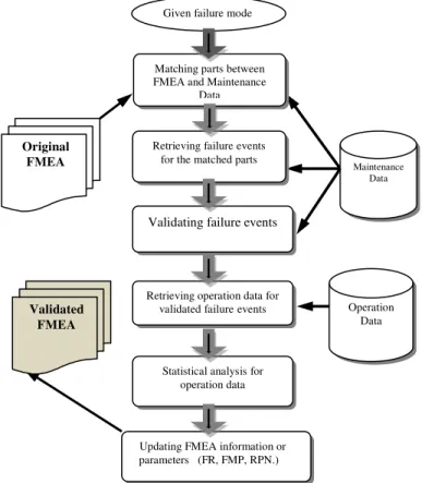
Figure 1 illustrates the proposed approach for FMEA validation. The various tasks can be grouped into three main phases:
1. Obtain the failure events from maintenance database given a failure mode in FMEA
2. Gather the relevant data for the failure events and conduct the statistical analysis for APU usage time 3. Update the FMEA parameters using statistical
information
2.1 Obtaining Failure Events
The goal is to retrieve information for all relevant failure events or component replacements from the maintenance database that relate to the given failure effect. In this case, we want to retrieve all occurrences of replacement of components that relate to the APU “Inability to Start” effect. The components of interest are the ones identified in the FMEA as contributors to the failure effect “Inability to Start”. As we mentioned in previous section, retrieving these components is a difficult task for a number of reasons: part numbers change over time and we often ended up with several numbering schemes, data entry errors or omission errors, technicians’ personal preference when entering part names when referring to a given component, and sometimes a component is mentioned in the textual description of the repair without being actually replaced. For example, in the database, we found that “ignitor”, “igniter”, “ignitor plug”, ‘ignition exciter’ and “ignition unit” are all use to refer to the component “Igniter”. All of these difficulties need to be taken into account when establishing part names (part description) and part IDs for a given component.
The second step uses the part numbers and part names identified to retrieve all occurrences of replacement of the given part (the so-called failure events) from the maintenance data. This step results in a list of occurrences of part replacements with detailed event information (e.g., repair date, aircraft identification number, and reason for replacement). Further validation is needed to remove duplicates and irrelevant entries from the list of occurrences.
Next, we analyze the maintenance history around each occurrence of replacement in order to get insights on other potentially related fixes (or components). In this work, we considered all APU maintenance repairs in the 60 day interval around each replacement event (i.e., up to 30 days before the given replacement and up to 30 days after the replacement). A number of software tools were developed to help automate the search but manual validation is still needed.
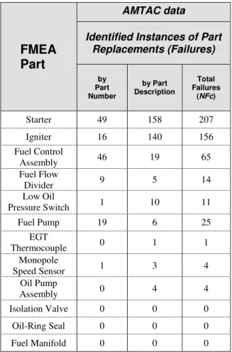
Table 1 shows the preliminary results obtained. The left column lists the components contributing to the failure effect considered (“Inability to Start”) based on the FMEA.
The other three columns show the number of replacement occurrences found using the part ID only and the part name only, respectively. From Table 1, we observe that we have been able to retrieve a significant number of occurrences of
Figure 1. The procedure of FMEA validation
Retrieving failure events for the matched parts
Original FMEA Operation Data Maintenance Data Matching parts between
FMEA and Maintenance Data
Validating failure events
Retrieving operation data for validated failureevents
Statistical analysis for operation data
Updating FMEA information or parameters (FR, FMP, RPN.)
Given failure mode
Validated FMEA
replacement for some FMEA components contributing to the selected failure effect. However, very few or even no replacements have been found for other FMEA contributing components such as Fuel Manifold and O-Ring Seal. This is surprising as the operator’s maintenance database covers more than 10 years of operation for a fleet of over 100 aircraft. A couple of hypotheses may be proposed to explain this situation. It is possible that some of the contributing components mentioned in the FMEA simply never failed during the period of maintenance data. Since the FMEA APU and APU used in the study is not the same model, it is also possible that some of the contributing components mentioned in the FMEA do not exist in the APU used in the study.
For the rest of the analysis, we focused on the contributing components which were actually replaced and ignored the other components.
FMEA
Part
AMTAC data
Identified Instances of Part Replacements (Failures) by Part Number by Part Description Total Failures (NFc) Starter 49 158 207 Igniter 16 140 156 Fuel Control Assembly 46 19 65 Fuel Flow Divider 9 5 14 Low Oil Pressure Switch 1 10 11 Fuel Pump 19 6 25 EGT Thermocouple 0 1 1 Monopole Speed Sensor 1 3 4 Oil Pump Assembly 0 4 4 Isolation Valve 0 0 0 Oil-Ring Seal 0 0 0 Fuel Manifold 0 0 0
Table 1. Instances of replacements for components for failure effect, ‘Inability to Start”
2.2 Data Analysis for APU Usage Time
In order to compute statistics about actual failure rate, we need to determine the cumulative usage of the entire fleet of APU over the period covered by the maintenance data. This is done by retrieving the most recent value of the APU_OPERATIING_HOUR parameter, which is automatically reported as part of the APU starting report, for each APU and then adding all values. For the dataset considered, we obtained a total APU usage of 4,328,083 operating hours (noted as UT). In the later section, we use this life consumption of APU engine when updating the FMEA parameters.
2.3 Updating FMEA Parameters
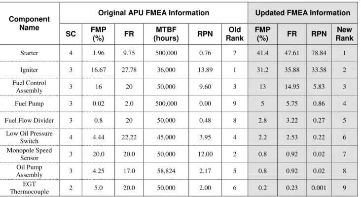
As mentioned before, we are interested in updating quantitative FMEA information, such as FR, FMP, SC, and MTBF. We also considered the “Risk Priority Number” (RPN) (Sellappan and Sivasubramanian 2008, ASENT 2009), which is defined as the product of SC, FMP, and FR. The RPN is a measure used when assessing risk to help identify critical component associated with the failure effect. A large RPN indicates that the given component is more likely to need replacement. The left hand side of Table 2 presents the values for all parameters of interest for each components for which we have been able to retrieve examples of replacements from the maintenance data. Based on RPN, most occurrences of APU “Inability to Start” problems should be resolved by replacing either the “Igniter” or the “Monopole Speed Sensor”. However, when considering the number of actual replacements (NFc in Table 1), we notice that the “Starter” comes first, followed by the “Igniter” and the “Fuel Control Assembly”. Moreover, the “Monopole Speed Sensor” which was one of the first components to be suspected based on original FMEA is almost never replaced by the maintenance crew (only 4 replacements as reported in Table 1). Such discrepancies between the original FMEA information and real maintenance practice clearly show the need for regular updates of the FMEA information.
We propose to update the FMEA information by relying on data acquired as part of normal operation. First, to update the FR and FMP parameters based on actual maintenance history, we introduce the following equations
UT
NFc
FR
=
--- (1)RN
NFc
FMP
=
--- (2) where:• NFc: The number of replacements of a given component (Table 1);
• UT: The total APU usage (in hours) for the entire fleet; it is 4,328,083 hours in this study; • RN: The total number of APU parts replaced during the investigation. It is a sum of NFc in Table 1. In this study, RN = 487.
4
The last four columns in Table 2 show the revised information. FMP and FR are computed from Eq. (1) and Eq.(2) using NFc from Table 1 and UT obtained as described above. RPN is recomputed using the revised parameters. The revised RPN results closely reflect the real maintenance practice. We also add ranking information based on RPN. The larger RPN number is associated with a higher ranking (a smaller value of ranking). The ranking parameter is useful for component ranking during fault identification as described in next section. We believe that the revised information, although quite different from the original number, are more representative of real world practice and therefore potentially more appropriate for decision-based support system to assist the operator in the maintenance of the APUs.
3. TSM REVISION
Troubleshooting is the process of diagnosing the source of a problem. It is used to fix problems with physical components or subsystems in a complex system. The basic theory of troubleshooting is that you start with the most general (and often most obvious) possible problems, and then narrow it down to more specific issues.
In this study, the APU TSM is provided by an OEM to enable the systematic identification, isolation and correction of aircraft warnings and malfunctions reported in flight and on the ground.
Like all TSMs, the provided APU TSM is a highly structured document designed to help identify and
isolate the fault by performing prescribed procedures. There is at least one chapter for each failure effect and each chapter contains 4 sections:
• Possible Causes, • Job Set-up Information, • Fault Confirmation, and • Fault Isolation Procedure (FIP).
Appendix A is an example of the original TSM chapter. Given a failure mode, the Possible Causes section lists the possible components which may contribute to the given failure mode or effect. This list is not ordered and has no priority for each component. Therefore, it is difficult for the end user to decide where to start the investigation. Most mechanics perform troubleshooting based on the symptoms, TSM, and their experiences. They use a sequential trial and error approach with guidance from the TSM until a solution is found. The Job Set-up Information section lists the AMMs (Aircraft Maintenance Manuals), which may relate to the FIPs and provides the detail instructions for installing or removing a contributing component. The Fault Confirmation section advises technicians how to check and test the failure symptoms in order to confirm the failure effects. Finally, the FIP section lists the ordered procedures for fixing failures. Depending on the type of failure, the problem symptoms could lead into a lengthy troubleshooting session especially when addressing intermittent
Component Name
Original APU FMEA Information Updated FMEA Information
SC FMP (%) FR MTBF (hours) RPN Old Rank FMP (%) FR RPN New Rank Starter 4 1.96 9.75 500,000 0.76 7 41.4 47.61 78.84 1 Igniter 3 16.67 27.78 36,000 13.89 1 31.2 35.88 33.58 2 Fuel Control Assembly 3 16 20 50,000 9.60 3 13 14.95 5.83 3 Fuel Pump 3 0.02 2.0 500,000 0.00 9 5 5.75 0.86 4
Fuel Flow Divider 3 0.8 20 50,000 0.48 8 2.8 3.22 0.27 5
Low Oil Pressure
Switch 4 4.44 22.22 45,000 3.95 4 2.2 2.53 0.22 6 Monopole Speed Sensor 3 20.0 20.0 50,000 12.00 2 0.8 0.92 0.02 7 Oil Pump Assembly 3 4.25 17.0 58,824 2.17 5 0.8 0.92 0.02 8 EGT Thermocouple 2 5.0 20.0 50,000 2.00 6 0.2 0.23 0.001 9
Note: (1) Risk Priority Number = SC · FMP · Rate; (2) Failure Rate (FR) is failures in million hours; (3) The shaded columns show the updated parameters
.
failures. To reduce costs and improve the efficiency of fixing a failure, it is expected that TSM can provide relatively accurate and accountable FIPs, such that technicians can quickly insolate the contributing components for fixing the failure.
There exist two issues with TSMs. First, the Possible Causes are not ordered and have no priority information. Second, the FIP may become out of date with respect to the aircraft and ultimately provide an inappropriate procedure for troubleshooting or fault isolation. In this work, we attempted to set an order for the Possible Causes and modify the FIP to reflect the historical maintenance experiences when suggesting a troubleshooting procedure. In particular, we update the Possible causes and FIP by using the “new rank” information from Table 2. We now detail this procedure.
3.1 Procedure of TSM Updating
The developed procedure for updating TSM based on the validated FMEA contains the following three steps.
1. Retrieve the relevant TSM standard chapters for the failure mode or effect of interest.
2. Verify that the order of the possible causes in the TSM corresponds to the ranking obtained with the validated FMEA. In case of discrepancies, update the Possible Causes section so that components are presented in the same order as shown in Table 2. 3. As needed, also align the FIP orders in the TSM
with the ranking provided by the validated FMEA. We repeat these steps for all chapters in the TSM that relate to the failure of interest.
3.2 The Preliminary Results
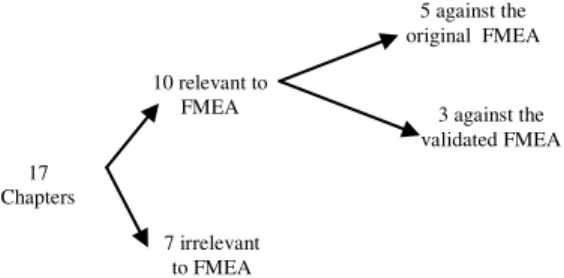
Following the procedure above, we updated the chapters related to the failure mode “Inability to Start” in APU TSM document. We first retrieved all chapters. There are 17 chapters in APU TSM document. Among them, only ten chapters contain the contributing components which appear
in FMEA document. We focused on these ten chapters. Second, we checked the consistency between the TSM and the validated FMEA or the original FMEA for those ten chapters. The Figure 2 shows the result of the ten chapters against the validated FMEA and the original FMEA. For the original FMEA the “old rank” data is used; for the validated FMEA, the ‘new rank” data is used. Both “rank” data are from Table 2.
Finally, we updated the three chapters where we found discrepancies with the validated FMEA following the steps explained above. Appendix B shows the results of this process when applied to the original TSM chapter shown in Appendix A. After the revision, the order for the Possible Causes became:
• IGNITER PLUG • GNITION UNIT P10 • FUEL CONTROL UNIT • OIL PUMP
• FLOW DIVIDER AND DRAIN VALVE ASSY • PRIMARY FUEL NOZZLE AND MANIFOLD • SECONDARY FUEL NOZZLE AND MANIFOLD • ECB (59KD)
We also revised the sequences of FIPs by changing the procedure of replacing OIL PUMP to follow the new rank of the validated FMEA. We highlighted the changes in italics in Appendix B. Such revisions of the TSM FIPs will improve the maintenance efficiency by reducing irrelevant component replacements and also potentially help with planning/scheduling troubleshooting (e.g., right people, right parts). For example, every time the root contributing component is FUEL CONTROL UNIT, the revised TSM will allow the technician to converge to the solution by investigating three components instead of four as initially recommended by TSM FIPs. Since this component fails relatively frequently, this simple change may lead to significant gain in efficiency over time.
4. DISCUSSION
TSM updating depends on the validated FMEA. Most FMEAs are created during the design phase of a system or product and the information may not be accurate enough for practical maintenance decision support system. FMEA should be regularly updated and validated in order to accurately reflect the fleet operation reality. This updated FMEA would provide more reliable and accurate information to enhance the TSM revision.
We only demonstrated the feasibility to update TSM documents using the validated FMEA by showing one failure mode, the ‘Inability to Start”. There are a large number of failure modes in TSM documents. Trying to update the full TSM would represent a significant undertaking. The main challenge comes from the 17 Chapters 10 relevant to FMEA 7 irrelevant to FMEA 5 against the original FMEA 3 against the validated FMEA
Figure 2. The TSM chapters for “Inability to Start” failure model
validation of FMEA. In particular, as noted in the paper, the processing of large amounts of historical maintenance data, which are often characterized by incompleteness and ambiguities, is time consuming and difficult to automate. This might be addressed by integration of even more advanced text processing techniques. An alternative would be to remove free text fields from maintenance data and implement better data validation tool to increase data quality.
There is also a gap between TSM and FMEA documents. For example, we found 7 TSM chapters which could not link to FMEA because the contributing components to the “Inability to Start” effect were completely different. We currently have no explanation for such a gap. Reconciliation would require the participation of the OEM and the end users. As we mentioned in the previous paper (Yang et al, 2009), there is also discrepancies between FMEA document and the operational and maintenance data. All of these create more challenges when updating TSM and validating FMEA.
Other challenges exist in updating TSM that are not related to the data collected from the end users. For example, we have to deal with some business and legal issues. One is the possible effect of the result with respect to the business process within the OEM because updated FMEA and TSM may request the unforeseen changes in the design of the system or component that may enhance the reliability of the system. Also, trade secrets, intellectual property, and competitive advantages can make the OEM reluctant in disclosing its FMEA and design documentation. In turn, this makes it more difficult to validate FMEA and update TSM. Finally, the TSM is considered a legal document that operator must follow in the maintenance. Modifications to this document without OEM consent may have legal ramifications and this issue must be investigated before implementing this procedure into the maintenance organization.
We believe in that the validated FMEA, in particular, the ranking information in Table 2 provides the useful resource for improving fault identification/isolation for a given failure effect or mode. Usually, when a failure has occurred, we have to identify which component is the root cause or to isolate the fault to a specific contributing component in order to schedule a maintenance action. As we introduced, we can use the revised TSM to isolate the root contributing component. However, TSM-based fault isolation procedure is still complicated and time consuming. To further enhance the troubleshooting procedures, we are developing a data mining-based fault isolation technology for PHM systems, which applies the updated FMEA to rank models and uses the operation data prior to failures as input to identify the root contributing component for a given failure mode. Initial results from this work were presented in another paper (Yang, et al, 2010).
5. CONCLUSION
In this paper, we proposed to update TSM by using the updated FMEA which is validated using historical
operational and maintenance data. We conducted the TSM revision for the failure mode of the “Inability to Start” by using the corresponding ranking information from the validated FMEA. The preliminary results obtained suggest that the validated FMEA provides more reliable and accurate information for updating TSM documents. The revised TSM provides more accurate information and reliable procedure for isolating the root components given a failure mode or effect.
ACKNOWLEDGMENT
Many people at the National Research Council Canada have contributed to this work. Special thanks go to Xijia Wu for providing the electronic FMEA documents and to Jeff Bird and Ken McRae for their support and valuable insights.
NOMENCLATURE
FR failure rate
FMP failure mode probability MTBF mean time between failures
NFc number of replacements of a Component RN total number of APU unit replaced RPN risk priority number
SC severity class of a failure mode UT total APU usage time
REFERENCES
ASENT FMEA Software. (2009). FMEA RPN, available at http://www.fmea-fmeca.com/fmea-rpn.html, 2009. C. Yang, S. Létourneau, E. Scarlett, and M. Zaluski.
(2009). APU FMEA Validation using Operation and Maintenance Data, in Proceedings of the Annual Conference of the Prognostics and Health Management Society. San Diego, CA, USA October 2009
M. Zaluski, N. Japkowicz, and S. Matwin. (2003). Case Authoring from Text and Historical Experiences, in Proceedings of the Sixteenth Canadian Conference on Artificial Intelligence (AI2003), June 11-13, 2003 N. Sellappan and R. Sivasubramanian. (2008). Modified
Method for Evaluation of Risk Priority Number in Design FMEA, The Icfai Journal of Operations Management, Vol. 7, No. 1, pp. 43-52, February 2008 C. Yang, S. Létourneau, M. Zaluski, and E. Scarlett
(2010), FMEA Validation and Its Application to Fault Identification, In Proceedings of the ASME 2010 International Design Engineering Technical Conference & Computer and Information in Engineering Conference, August 15-18, 2010, Montreal, Quebec, Canada
Dr. Chunsheng Yang is a Senior Research Officer at the Institute for Information Technology of the National Research Council of Canada. Chunsheng is interested in data mining, machine learning, reasoning technologies such as case-based reasoning, rule-based reasoning and hybrid reasoning, multi-agent systems, and distributed computing. Chunsheng received a B.Sc. (Hon.) in Electronic Engineering from Harbin Engineering University, China, an M.Sc. in computer science from Shanghai Jiao Tong University, China, and a Ph.D. from National Hiroshima University, Japan. Chunsheng worked with Fujitsu Inc., Japan, as a Senior Engineer and engaged on the development of ATM Network Management Systems. Chunsheng has been the author for over 50 papers and book chapters published in the referred journals and conference proceedings. Chunsheng was a Program Co-Chair for the 17th International Conference on Industry and Engineering Applications of Artificial Intelligence and Expert Systems. Chunsheng was a guest editor for the International Journal of Applied Intelligence. Chunsheng, as a senior IEEE member, has served Program Committees for many conferences and institutions, and has been a reviewer for many conferences, journals, and organizations, including Applied Intelligence, NSERC, IEEE Trans., ACM KDD, PAKDD, AAMAS, IEA/AIE, etc.
Dr. Sylvain Létourneau a Senior Research Council Officer with the National Research Council of Canada. Sylvain received his BS in computer science and mathematics and his MS in multi-agent systems from Université Laval in Québec City. He obtained his Ph.D. in machine learning from University of Ottawa. Sylvain is now leading the data mining group on Equipment Health Management at the Institute for Information Technology, National Research Council Canada.
Marvin Zaluski is with the Institute for Information Technology at the National Research Council Canada (NRC-IIT). Marvin received his B.Sc. (Hon.) with Honors from the University of Regina in Saskatchewan. Since joining the NRC-IIT in 1996, Marvin has received his Masters in Computer Science at the University of Ottawa in 2003. Marvin is involved in the development of knowledge discovery and knowledge management tools. His current work focuses on the development of data mining-based models for assisting maintenance personnel and managers in predicting faults on board jet aircraft. Marvin has experience working with companies in aerospace and open pit surface mining.
Appendix A: A chapter in TSM for the “inability to Start”
TASK 49-00-00-810-821 **ON A/C 201-234, 251-285, 401-449,APU AUTO SHUT DOWN - NO FLAME, Ignition System -, or Fuel Control Unit -, or ECB 59KD - Fault (GTCP36-300)
- IGNITER PLUG 1. Possible Causes
- IGNITION UNIT P10 - OIL PUMP
- FUEL CONTROL UNIT
- FLOW DIVIDER AND DRAIN VALVE ASSY - PRIMARY FUEL NOZZLE AND MANIFOLD - SECONDARY FUEL NOZZLE AND MANIFOLD - ECB (59KD)
A. Referenced Information 2. Job Set-up Information
______________________________________________________________________
REFERENCE DESIGNATION
AMM 28-22-00-710-001 Operational Test of the APU Fuel-Pump System on Ground to Purge the Fuel Line
AMM 49-00-00-710-004 Operational Test of the APU (4005KM) (GTCP 36-300)
AMM 49-31-41-000-001 Removal of the Primary Fuel Nozzle and Manifold (8020KM) (GTCP 36-300) AMM 49-31-41-400-001 Installation of the Primary Fuel Nozzle and Manifold (8020KM) (GTCP 36-300) AMM 49-32-11-000-001 Removal of the Fuel Control Unit (FCU) (8022KM) (GTCP 36-300)
AMM 49-32-11-400-001 Installation of the Fuel Control Unit (FCU) (8022KM) (GTCP 36-300)
AMM 49-32-12-000-001 Removal of the Flow Divider and Drain Valve Assembly (8023KM) (GTCP 36-300)
AMM 49-32-12-400-001 Installation of the Flow Divider and Drain Valve Assembly (8023KM) (GTCP 36-300)
AMM 49-41-38-000-001 Removal of the Ignition Unit (8030KM) (GTCP 36-300) AMM 49-41-38-400-001 Installation of the Ignition Unit (8030KM) (GTCP 36-300) AMM 49-41-41-000-001 Removal of the Igniter Plug (8031KM) (GTCP 36-300) AMM 49-41-41-400-001 Installation of the Igniter Plug (8031KM) (GTCP 36-300) AMM 49-41-43-000-001 Removal of the Electrical Lead - Igniter Plug (GTCP 36-300) AMM 49-41-43-400-001 Installation of the Electrical Lead - Igniter Plug (GTCP 36-300) AMM 49-61-34-000-001 Removal of the Electronic Control Box (ECB) (59KD) (GTCP 36-300) AMM 49-61-34-400-001 Installation of the Electronic Control Box (ECB) (59KD) (GTCP 36-300) AMM 49-91-45-000-001 Removal of the Oil Pump (8080KM) (GTCP 36-300)
AMM 49-91-45-400-001 Installation of the Oil Pump (8080KM) (GTCP 36-300)
A. Purging of the APU Fuel Feed-Line and Test 3. Fault Confirmation
(1) Purge the APU fuel-feed line AMM TASK 28-22-00-710-001.
NOTE : If the fuel supply to the APU is not correct, do the applicable troubleshooting procedure(s) in the Chapter 28.
(2) Do the operational test of the APU AMM TASK 49-00-00-710-004.
A. If an APU auto shutdown occurs during the APU start sequence and the APU SHUTDOWNS report gives the maintenance message:
NO FLAME - CHECK IGNITION SYSTEM OR FCU OR ECB 59KD: -do a check at the APU compartment drain-mast for fuel drain. (1) If there is no fuel drain:
-go to step (5). (2) If there is fuel drain:
-replace the IGNITER PLUG
-AMM TASK 49-41-41-000-001 and AMM TASK 49-41-41-400-001. (3) If the fault continues:
-replace the IGNITER PLUG ELECTRICAL-LEAD
-AMM TASK 49-41-43-000-001and AMM TASK 49-41-43-400-001 . (4) If the fault continues:
-replace the IGNITION UNIT P10
-AMM TASK 49-41-38-000-001and AMM TASK 49-41-38-400-001. (5) If the fault continues:
-remove the FUEL CONTROL UNIT P19 -AMM TASK 49-32-11-000-001,
NOTE : TURN THE MANUAL DRIVE SHAFT OF THE STARTER MOTOR WITH A TORQUE WRENCH. THE TORQUE LIMIT IS 29 lbf.ft (3.9318 m.daN) . DO NOT TURN THE SHAFT WITH A TORQUEMORE THAN THE LIMIT. A TORQUE MORE THAN THE LIMIT WILL DAMAGE THE COMPONENT.
-to make sure that the oil pump input-shaft is not broken, turn the manual drive shaft of the starter motor(8KA) in a counterclockwise direction (the direction of the arrow on the housing) and make sure that the oil pump output-shaft (which drives the FCU) turns constantly. (a) If the oil pump output-shaft does not turn constantly (the oil pump input-shaft is broken):
-replace the OIL PUMP
-AMM TASK 49-91-45-000-001and AMM TASK 49-91-45-400-001, -install a serviceable FUEL CONTROL UNIT P19
-AMM TASK 49-32-11-400-001. 1
-install a new FUEL CONTROL UNIT
If the oil pump output-shaft turns constantly (the oil pump input-shaft is not broken): -AMM TASK 49-32-11-400-001.
(b) If the fault continues:
-replace the FLOW DIVIDER AND DRAIN VALVE ASSY
-AMM TASK 49-32-12-000-001and AMM TASK 49-32-12-400-001. (c) If the fault continues:
-replace the PRIMARY FUEL NOZZLE AND MANIFOLD
-AMM TASK 49-31-41-000-001and AMM TASK 49-31-41-400-001. -replace the SECONDARY FUEL NOZZLE AND MANIFOLD -AMM TASK 49-31-41-000-001and AMM TASK 49-31-41-400-001 . (d) If the fault continues:
-replace the ECB (59KD)
-AMM TASK 49-61-34-000-001and AMM TASK 49-61-34-400-001. B. Do the operational test of the APU AMM TASK 49-00-00-710-004.
Appendix B: The revised chapter for the original document in Appendix A.
TASK 49-00-00-810-821 **ON A/C 201-234, 251-285, 401-449,APU AUTO SHUT DOWN - NO FLAME, Ignition System -, or Fuel Control Unit -, or ECB 59KD - Fault (GTCP36-300)
- IGNITER PLUG 1. Possible Causes
- IGNITION UNIT P10 - FUEL CONTROL UNIT - OIL PUMP
- FLOW DIVIDER AND DRAIN VALVE ASSY - PRIMARY FUEL NOZZLE AND MANIFOLD - SECONDARY FUEL NOZZLE AND MANIFOLD - ECB (59KD)
A. Referenced Information 2. Job Set-up Information
______________________________________________________________________
REFERENCE DESIGNATION
AMM 28-22-00-710-001 Operational Test of the APU Fuel-Pump System on Ground to Purge the Fuel Line
AMM 49-00-00-710-004 Operational Test of the APU (4005KM) (GTCP 36-300)
AMM 49-31-41-000-001 Removal of the Primary Fuel Nozzle and Manifold (8020KM) (GTCP 36-300) AMM 49-31-41-400-001 Installation of the Primary Fuel Nozzle and Manifold (8020KM) (GTCP 36-300) AMM 49-32-11-000-001 Removal of the Fuel Control Unit (FCU) (8022KM) (GTCP 36-300)
AMM 49-32-11-400-001 Installation of the Fuel Control Unit (FCU) (8022KM) (GTCP 36-300)
AMM 49-32-12-000-001 Removal of the Flow Divider and Drain Valve Assembly (8023KM) (GTCP 36-300)
AMM 49-32-12-400-001 Installation of the Flow Divider and Drain Valve Assembly (8023KM) (GTCP 36-300)
AMM 49-41-38-000-001 Removal of the Ignition Unit (8030KM) (GTCP 36-300) AMM 49-41-38-400-001 Installation of the Ignition Unit (8030KM) (GTCP 36-300) AMM 49-41-41-000-001 Removal of the Igniter Plug (8031KM) (GTCP 36-300) AMM 49-41-41-400-001 Installation of the Igniter Plug (8031KM) (GTCP 36-300) AMM 49-41-43-000-001 Removal of the Electrical Lead - Igniter Plug (GTCP 36-300) AMM 49-41-43-400-001 Installation of the Electrical Lead - Igniter Plug (GTCP 36-300) AMM 49-61-34-000-001 Removal of the Electronic Control Box (ECB) (59KD) (GTCP 36-300) AMM 49-61-34-400-001 Installation of the Electronic Control Box (ECB) (59KD) (GTCP 36-300) AMM 49-91-45-000-001 Removal of the Oil Pump (8080KM) (GTCP 36-300)
AMM 49-91-45-400-001 Installation of the Oil Pump (8080KM) (GTCP 36-300)
A. Purging of the APU Fuel Feed-Line and Test 3. Fault Confirmation
(1) Purge the APU fuel-feed line AMM TASK 28-22-00-710-001.
NOTE : If the fuel supply to the APU is not correct, do the applicable troubleshooting procedure(s) in the Chapter 28.
(2) Do the operational test of the APU AMM TASK 49-00-00-710-004.
A. If an APU auto shutdown occurs during the APU start sequence and the APU SHUTDOWNS report gives the maintenance message:
4. Fault Isolation
This list is ordered with the rank information from the validated FMEA.
NO FLAME - CHECK IGNITION SYSTEM OR FCU OR ECB 59KD: -do a check at the APU compartment drain-mast for fuel drain. (1) If there is no fuel drain:
-go to step (5). (2) If there is fuel drain:
-replace the IGNITER PLUG
-AMM TASK 49-41-41-000-001 and AMM TASK 49-41-41-400-001. (3) If the fault continues:
-replace the IGNITER PLUG ELECTRICAL-LEAD
-AMM TASK 49-41-43-000-001and AMM TASK 49-41-43-400-001 . (4) If the fault continues:
-replace the IGNITION UNIT P10
-AMM TASK 49-41-38-000-001and AMM TASK 49-41-38-400-001. (5) If the fault continues:
-remove the FUEL CONTROL UNIT P19 -AMM TASK 49-32-11-000-001,
NOTE : TURN THE MANUAL DRIVE SHAFT OF THE STARTER MOTOR WITH A TORQUE WRENCH. THE TORQUE LIMIT IS 29 lbf.ft (3.9318 m.daN) . DO NOT TURN THE SHAFT WITH A TORQUE MORE THAN THE LIMIT. A TORQUE MORE THAN THE LIMIT WILL DAMAGE THE COMPONENT.
-to make sure that the oil pump input-shaft is not broken, turn the manual drive shaft of the starter motor(8KA) in a counterclockwise direction (the direction of the arrow on the housing) and make sure that the oil pump output-shaft (which drives the FCU) turns constantly. (a) If the fault continues:
-install a new FUEL CONTROL UNIT -AMM TASK 49-32-11-400-001.
(b) If the fault continues and the oil pump output-shaft does not turn constantly (the oil pump input-shaft is broken):
-replace the OIL PUMP
-AMM TASK 49-91-45-000-001and AMM TASK 49-91-45-400-001, -If the oil pump output-shaft turns constantly
(the oil pump input-shaft is not broken):
-replace the FLOW DIVIDER AND DRAIN VALVE ASSY
-AMM TASK 49-32-12-000-001and AMM TASK 49-32-12-400-001. (c) If the fault continues:
-replace the PRIMARY FUEL NOZZLE AND MANIFOLD
-AMM TASK 49-31-41-000-001and AMM TASK 49-31-41-400-001. -replace the SECONDARY FUEL NOZZLE AND MANIFOLD -AMM TASK 49-31-41-000-001and AMM TASK 49-31-41-400-001 . (d) If the fault continues:
-replace the ECB (59KD)
-AMM TASK 49-61-34-000-001and AMM TASK 49-61-34-400-001. B. Do the operational test of the APU AMM TASK 49-00-00-710-004.
Revision:2011-04-01 Print Date: 2011-04-06 49-00-00
This FIP is updated with the rank information from the validated FMEA.