Automated Remote Microscope for Inspection
of Integrated Circuits
by
Somsak Kittipiyakul
Submitted to the Department of Electrical Engineering and Computer Science in Partial Fulfillment of the Requirements for the Degree of
Bachelor of Science in Electrical Engineering
and Master of Engineering in Electrical Engineering and Computer Science
at the MASSACHUSETTS INSTITUTE OF TECHNOLOGY
September 6, 1996
© Somsak Kittipiyakul, 1996. All rights reserved. The author hereby grants to M.I.T. permission to reproduce, to distribute publicly paper and electronic copies of this thesis
and to grant others the right to do so.
Author
Department of Electrical Engineering and Computer Science September 6, 1996
Certified by
/ ' Donald E. Troxel
Professor of Electrical Engineering Thesis Supervisor
Certified by
~.\~~CF
Frederic R. Morgenthaler ChairmanDepartment Committee on Graduate Students
-• ..• •
Automated Remote Microscope for Inspection
of Integrated Circuits
by
Somsak Kittipiyakul
Submitted to the
Department of Electrical Engineering and Computer Science
In Partial Fulfillment of the Requirements for the Degree of
Bachelor of Science in Electrical Engineering
and Master of Engineering in Electrical Engineering and Computer Science
Abstract
The MIT remote microscope system being developed as part of the Computer Aided Prototyping of Advanced Microsystems project has demonstrated the feasibility of a remote microscope which operates over the internet and its effectiveness to inspect inte-grated circuits during remote fabrication. It also helps to provide more collaboration and sharing of resources among researchers in the field of semiconductors. However, because the first generation remote microscope was controlled manually by an attendant, an auto-mation of the remote microscope provides a full computer control and a better precision, convenience, and computer-based analysis of images. In addition, the automated remote microscope will be able to support new valuable functionalities that require exact and automatic positioning of the microscope. Thus, the automation of the remote microscope raises the value and effectiveness of the initial remote microscope as a remote inspection tool and collaboration tool during remote or even local semiconductor fabrication.
Thesis Supervisor: Donald E. Troxel
Acknowledgments
I would like to thank Professor Troxel deeply for his kind support and advice through-out this past year. In addition to support me financially as a research assistant, he haS given me good advice for many times when I had problems with my research. Because English is not my first language, I have a lot of trouble of explaining things, but he always tries to listen to my poor English and helps me with my bad writing. I am grateful to have such a
generous adviser as Professor Troxel.
I also would like to thank James Kao who is the first person to start this remote micro-scope project. He patiently taught me what he had done for the micromicro-scope project and suggested many valuable ideas. His basic architecture of the remote microscope was nicely done and thus makes the incorporate of the automated microscope which is the important part of my thesis easily. Actually, my thesis includes and mentions a lot of his thesis. I would like to thank William Moyne for his help and his great knowledge about computer. I am grateful for everyone in the CIDM group for suggestion and support.
My family and my friends at MIT have provided inspiration and support for me to progress and go on with my research.
Table of Contents
List of Figures ... ... 7
List of Tables... ... 9
Chapter 1 Overview ... 10
Chapter 2 Background ... 16
2.1 The First Generation of the Existing MIT Remote Microscope ... 16
2.2 Incorporation of Automation to the Remote Microscope ... 18
Chapter 3 Functionality of the Automated Remote M icroscope ... 20
3.1 Automation of the Microscope ... 20
3.2 Overall operation of the automated microscope ... ... 21
3.3 Client User Interface ... 23
3.3.1 The Client's Control Window ... ... 26
3.3.2 Client's Display Windows: Window A and Window B... 29
3.3.3 Auto Focusing... 30
Chapter 4 Hardware Implementation... ... ... 32
4.1 Automated Microscope System ... 34
Chapter 5 Software System Overview ... 36
5.1 Architecture of the Automated Remote Microscope System... ... 36
5.2 Microscope Controller Module ... 38
5.3 Additional Messaging for Automated Remote Microscope ... 40
Chapter 6 Important Features of the Current Automated Microscope ... 43
6.1 Built-In Automatic Focus Algorithm ... ... ... 43
6.2 Offsets for Objectives ... 48
6.3 Depths of Focus ... 54
6.4 Built-In Safety Mechanism ... 54
Chapter 7Automated Microscope Controller Module: Software Implementation Details
... 56
7.1 Tools to Operate the Automated Microscope... ... ... 56
7.2 Movement Algorithm... 58
7.2.1 Focus Map ... 59
7.2.2 Assumptions about Safe Movement ... ... 61
7.2.3 Movement Strategy...62
7.2.4 Offset Calibration ... 67
7.2.5 Coordinate Transformations ... 69
7.2.6 Estimation of Focus Position ... ... 71
7.3 Dynamically Handlings of Messages... 78
7.4 Communication with the Automated Microscope ... ... 79
Chapter 8 Software Implementation of the Modified Microscope Server...81
8.1 Maintaining Current States of Images and Microscope ... 82
8.2 Handling of Client Requests ... 82
8.3 Video Module... 83
Chapter 9 Software Implementation of the Modified Client User Interface ... 86
9.1 Handling Inputs from the Client Interface ... ... 87
9.2 Coordinate Transformation ... 90
9.3 Handling Messages From Server ... 91
Chapter 10 Possible Improvements and Future W ork ... 92
10.1 Autofocus ... 92
10.2 Client User Interface ... 94
10.3 Image Quality ... ... 94
10.4 Future Functionalities ... 95
10.5 Authentication ... 96
Chapter 11 Conclusion...97
References ... 99
List of Figures
FIGURE FIGURE FIGURE FIGURE FIGURE FIGURE FIGURE FIGURE FIGURE FIGURE 1. 2. 3. 4. 5. 6. 7. 8. 9. 10. FIGURE 11. FIGURE FIGURE 12. 13. FIGURE 14. FIGURE FIGURE 15. 16. FIGURE 17. FIGURE FIGURE FIGURE 20.Remote microscope main console. ... ... 13
Remote microscope WINDOW A display ... 14
Remote microscope WINDOW B display. ...15
Overall Operation of the Automated Remote Microscope ...22
Initial connection window ... ... 23
"Console," WINDOW A," and "WINDOW B" windows that makes up client interface... ... ... 25
X, Y, and F coordinate system for the microscope stage position. ...26
Component setup for remote microscope ... 33
Architecture of the Automated Remote Microscope System. ...37
Microscope controller module in relation with the server and the video m odule... ... 39
Example of messaging between each programs for the "GRABFRAME" command ... 42
Plot of Ideal Focus Quality as a function of focus axis position ... 45
Example of the actual focus quality curves of every magnification lenses as a function of focus axis position... ... 47
Comparison of the focus quality curves of adjacent magnifications for three different areas on the same wafer... 51
Example of the Focus Map ... 60
Example of the "Safe" box around the current position of the microscope. It is assumed that the microscope can move safely within the safe box....61
Diagram of the movement strategy used by the Microscope Controller to move to new position, (nx, ny, nf), and with new magnification, nmag....65
Diagram for the "Safe" move algorithm. ... 66
Algorithm for changing magnification.. ... 67
FIGURE 21. FIGURE 22. FIGURE 23. FIGURE 24. FIGURE 25. FIGURE 26. FIGURE 27. FIGURE 28. FIGURE 29. FIGURE 30. FIGURE 31.
Transformation from the system coordinates to the microscope
coordinates... ... 70
Three-point linear interpolation/extrapolation...73
Two-point linear interpolation/extrapolation ... 74
The rule for qualification of the three points used for extrapolation... ... 75
The rule for qualification of the two points used for extrapolation... ...76
...7 6 Algorithm for estimation of focus position at the new (x, y) position and new magnification, nmag ... ... 77
An Example function provided by OS/2 for setting the baud rate of the RS-232 communication ... 80
Model of execution after receiving "GRABFRAME" message from daemon (originating from Tcl/Tk Client) ... 83
Code that is executed when the EXECUTE button is pressed...89
Transformation between the pixel coordinate system and the global coordinate system. ... 90
List of Tables
TABLE 1. Approximated cost of each component of the automated remote
microscope hardware. ... ... 33
TABLE 2. Commands for the Beltronics Automated Microscope System...34
TABLE 3. Additional and modified Message formats used between Tcl/Tk Client and D aem on... ...40
TABLE 4. Examples of the offsets between pairs of consecutive objectives. ...49
TABLE 5. X and Y offsets for each pair of consecutive objectives for the current m icroscope ... ... ... 53
TABLE 6. Approximated depths of focus for a plain wafer ... 54
TABLE 7. Package of tools to operate the automated microscope ... 57
TABLE 8. Messages used between the microscope controller and the server ... 78
TABLE 9. List of Variables related to the functions of the automated microscope ....86
TABLE 10. CHAT message passing tool ... 102
TABLE 11. Video module package ... 103
TABLE 12. Microscope controller package ... 103
TABLE 13. Server package ... ... 103
TABLE 14. Tcl/Tk client interface package ... 104
Chapter 1
Overview
The MIT remote microscope1 allows a user to remotely control and view a distant microscope over the internet. Although the remote microscope was primarily designed to be used as a remote inspection tool during a remote fabrication of integrated circuits, it is actually a general tool that will allow any user with an access to an X-window UNIX workstation to view any type of specimen under the microscope [Kao95]. The remote automated microscope which is the initial remote microscope incorporated with an auto-mated microscope provides a convenient, precise, and computer-controlled operation of the microscope. It provides a remote, hand-free microscope that needs no attendant other than for initial loading of a wafer.
The automated remote microscope is versatile; it operates over the internet and con-sists of a graphical user interface running on an X-window UNIX workstation that com-municates with a server program running on a PC connected to an automated inspection microscope. The server program also communicates to a microscope controller which controls the automated microscope and a video module that contains a frame grabber board which is capable of capturing a video signal from a CCD camera that is mounted on
1. The initial manual remote microscope version was developed by James Kao in the MIT CIDM group. The automated remote microscope is the modification of the initial manual remote microscope. See
the top of the microscope. To a user though, the remote microscope is simply a graphical user interface that runs on a workstation because the hardware implementation is hidden
from the user.
Typically, a user operates the microscope by setting an X-Y-F pan position,1 selecting a magnification setting of the microscope and a method of focusing (either automatic focus or manual focus) for the new image, and then requesting a new image from the microscope. When the server process receives a request, it relays the request to the micro-scope controller to position the micromicro-scope and do auto focus if requested. After the con-troller has notified the server that the microscope is ready for an image capture, the server directs the video module to grab a new image of size 640 x 480 pixels at 16 bits per pixel2 from the video camera. Then, the server transmits the image back to the client to be dis-played.
The remote microscope also allows multiple clients to connect to view the microscope at the same time during a conference inspection session. This allows any number of indi-viduals on the internet to simultaneously view the microscope cooperatively, which can be very productive and effective when semiconductor researchers work together during pro-cessing steps.
The current automated remote microscope enables inspection functionalities that require an exact coordinate positioning and computer-controlled movement of the micro-scope. The current automatic functionalities include automatic focusing, microscope posi-tioning, and changing of magnification. Other functionalities which might be added in the future include storing a sequence of images of the wafer during processing steps for later inspection, scanning the wafer to find areas of interest, computer-based analysis of micro-scope images such as finding defects on the wafer, and matching and comparing between a circuit layout and the actual wafer after processing steps. These possible applications of the automated remote microscope will prove to be useful even for inspection within local facility.
1. F-axis is the focus axis which is the vertical motion of the microscope stage.
2. Actually the colors are quantized to 200 colors which are used in the GIF format image before transmis-sion. See appendix A.
Because safety is a major concern in the remote operation of any automated micro-scopes, the current automated remote microscope has incorporated a safety check ensuring that no microscope objective will crash into the wafer as a user lets the microscope oper-ates automatically without his/her presence. Because the microscope does not have a sen-sor telling the distance of the objective and the wafer, it relies on the autofocus algorithm to find the optimal focus position which guarantees that the microscope is in a safe focus position.
The hardware needed to implement the automated remote microscope includes a PC running OS/2 Warp operating system, a framegrabber board, a high resolution CCD video camera mounted on an inspection microscope, and an automated microscope that has three computer-controlled stepper motors to control the microscope stage in the X-Y-F axes, a mechanism to select an objective lens, a programmable illuminator, and an RS-232 serial interface. The client, server, and microscope controller software was written at MIT and is easily exportable to other systems.
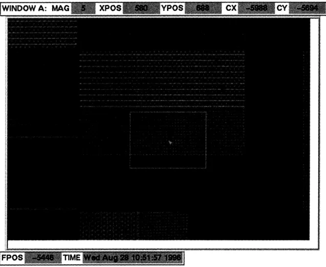
The user of the automated remote microscope is presented with a very natural inter-face to the microscope that provides two views of the microscope images. The user is allowed to set the magnification of the microscope, to set a new pan position by either entering coordinates or clicking on a region within the display windows, to set the method of focusing, and finally to initiate a capture where an image from the microscope is dis-played into a selected window. The following diagrams are screen dumps of the remote microscope main console and two display windows of microscope images.
CURRENT
MAGNIFICATION
SET MAGNIFICATION
FIGURE 1. Remote microscope main console.
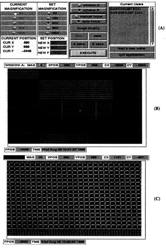
---FIGURE 2. Remote microscope WINDOW A display. This shows a panoramic view at 5x. The rectangle around the middle shows the region of interest that will be zoomed in. This next image is shown in Figure 3.
FPOS -3632 TIME Wed Aug 28 1052:54 199
FIGURE 3. Remote microscope WINDOW B display. This shows area of interest at 20x.
Chapter 2
Background
Being developed at MIT as part of the Computer Aided Prototyping of Advanced Microsystems project (CAPAM) supported by the Advanced Research Projects Agency, the remote microscope was designed "to provide an inspection tool to aid in the remote fabrication of integrated circuits, which hopefully will improve the efficiency and flexibil-ity of current semiconductor manufacturing technologies." By having an abilflexibil-ity to per-form different wafer processing steps at different facilities, wafer manufacturing can be more cost effective and robust. For example, expensive machines can be shared, rather than duplicated, among several facilities and wafers can be rerouted to different facilities if a machine goes down in a production line. In addition, the process designers and circuit designers can provide more interactive and collaborative role in maintaining quality by inspecting the wafer after each sensitive processing step at the remote facilities [Kao95].
2.1 The First Generation of the Existing MIT Remote Microscope
The initial remote microscope has demonstrated that it effectively allows a user to operate and view in "real-time," with a small delay, an actual microscope located at a dis-tant facility. Thus, it has exhibited the feasibility of a remote microscope to inspect wafers during remote fabrication. In addition, the remote microscope has proved to be extremely versatile; it operates over the internet and allows a user to run the graphical microscope interface on any standard X-windows UNIX terminal. It also allows multiple users to
view the microscope at the same time in a conference inspection. Thus, it provides more collaboration and sharing of resources among researchers in the field of semiconductors.
The MIT remote microscope was the first example of remotely viewing a microscope over the internet. The initial remote microscope was officially demonstrated between Stanford University and MIT, where users at Stanford could see and manipulate in real time a wafer located under a microscope at MIT. This was demonstrated at the August 1995 Stanford TCAD Symposium, "Hierarchical Technology CAD Process, Device, and Circuits," where the MIT-Stanford team described "A New Research Paradigm using Internet Collaboration" that would allow distributed researchers to work together in the semiconductor field [Kao95].
The software and hardware to implement the manual remote microscope uses avail-able parts. The hardware includes a PC running OS/2 Warp operating system, a Targa+ framegrabber board, and a video camera mounted on top of an inspection microscope. The software was developed here at MIT and easily exportable to other systems. Thus, the remote microscope is a highly portable, low cost solution to provide remote inspection capability to researchers.
The initial remote microscope system has proved to be a useful foundation for future development such as automation of the microscope. This prototype system provides a cli-ent graphical user interface that is fully interactive, user friendly, and functional. The com-munication among the client(s) and the server program has been implemented with the CHAT messaging system [Car95] which can easily incorporate new programs into the sys-tem by messaging interface between each program.
In addition, there is generally a delay greater than 30 seconds between when a user requests a new microscope image and when he/she finally receives the updated picture. Although tolerable, this delay should be reduced to make the microscope more effective. The delay consists of several factors, including the network delay, and most importantly delay due to converting the image file format from a TGA format provided by the frame grabber board to a GIF format utilized by the Tcl/Tk client. To speed up the conversion, the current automated remote microscope has improved the conversion.
2.2 Incorporation of Automation to the Remote Microscope
Initially, the remote microscope was controlled by an attendant who manually set the magnification, pan, and focus of the microscope whenever the server received a request for a new microscope image from the user. After the attendant had positioned the micro-scope properly, the server grabbed an image from the video camera mounted on top of an inspection microscope and sent the image back to the clients to be displayed. Because the exact way in which the microscope moves is irrelevant to the remote user, this manual setup would still appear, form the user point of view, to be fully automated [Kao95].
However, there are several difficulties in using this "manual" microscope. Not only this manual microscope needs an attendant to operate the microscope all the time, but also it is difficult to pan to the exact X-Y-F microscope coordinates. Thus, it does not allow the applications that need well known microscope coordinates and the capability of an auto-mated microscope such as automatic focusing, comparing the layout with the actual wafer after processing steps, and keeping record of wafer after each processing step.
The incorporation of the automation of the microscope thus provides a true remotely computer-controlled microscope and improves the usefulness of the remote microscope as an inspection tool for both remote and local inspection of integrated circuits. The auto-mated remote microscope requires presence of an attendant only for putting a wafer prop-erly on the microscope stage. After that, the microscope is able to pan, zoom, and do focusing automatically. Thus, a process designer can view and operate the microscope without suiting up to go into the clean room to operate the microscope. Integrating the automated remote microscope into the clean rooms would make the inspection process much more versatile, providing remote access as well as easy access to images in elec-tronic form.
The automation of the remote microscope will be proved much more useful in the future as new inspection functionalities are developed. We hope that it will enhance the existing capability of providing feedback between process designer and remote facility during collaborative semiconductor fabrication in the future.
the user, we must build a control algorithm that knows how to move the microscope stage and rotate the objective turret safely and thus not to crash the wafer. This automated con-trol operation will be based on the current microscope position and magnification and the autofocus analysis of the video images of the wafer.
Chapter 3
Functionality of the Automated Remote Microscope
The remote microscope system was initially built for remote fabrication and inspec-tion of integrated circuits. It enables a more collaborative and more distributed approach to fabrication of ICs. A user can have her wafer fabricated in the distant factory and still be able to inspect the wafer from her X-terminal and can do conference inspection with others engineers and designers. [Kao95].
The new functionality and improvement from the initial remote microscope system is mainly incorporation of automated microscope to the existing system. The general opera-tion and set up of the remote microscope system, thus, still remain unchanged. The system still allows a user to view and "virtually control" a microscope over the internet. It also provide a conference inspection for multiple clients. The client/server architecture and most of the client user interface still unchanged as was described in Kao's thesis. How-ever, to be able to fully control the automated microscope, a new version of the client user interface is introduced and the server has been modified to accommodate the automated microscope controller module.
3.1 Automation of the Microscope
In the initial version of the microscope system, the microscope is controlled manually
by an attendant. But the current microscope system is fully automated; an attendant is
has incorporated computer-controlled command interface to the microscope. Thus, a user can specify the position for the microscope stage to move to and the magnification. At the new position and new magnification before the new image frame is grabbed, the user must choose either he/she wants to use the automatic focus algorithm or manual focus, which the focus axis position for the microscope must be specified.
The true remotely controlled microscope is needed for convenience, precision, com-puter-based processing of images, and full computer control. However, the incorporation of the automatic microscope into the current system needs more functionality at the client user interface that will enable a user to set the pan and magnification, either manual focus or autofocus of the microscope. More details of how a user uses the automated microscope is discussed section 3.3.
3.2 Overall operation of the automated microscope
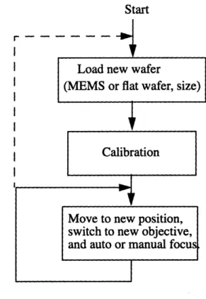
The overall operation of the automated microscope shown in Figure 4 starts with the loading of a new wafer onto the stage, wafer calibration, then it goes into a waiting loop for a user's requests to pan, change magnification of the microscope and do auto focusing, or to load a new wafer.
FIGURE 4. Overall Operation of the Automated Remote Microscope
Start
Load new wafer
(MEMS or flat wafer, size)
Calibration
1
I
Move to new position, switch to new objective, and auto or manual focus
In the current system, during loading a new wafer, the wafer is put at about the middle of the stage but with no accuracy in the location. This unspecification of the wafer position might cause a problem in the future when we needs to access the same position in a con-tinuous inspection of the same wafer for several wafer-processing steps. Thus we will need some kind of position marking such as a perpendicular corner or a mark indicating the previous position of the wafer.
Before the calibration of the new wafer, the user must specify type (MEMS or regular flat wafer), size, approximated thickness of the new wafer so that the system can adjust the system parameters for movement and focusing algorithms. These parameters are impor-tant for the safety of both the microscope lenses and the wafer itself since an objective might be able to crash into the wafer if the parameters are incorrectly specified. For exam-ple, for a flat wafer, the system can afford to move the stage while under a high magnifica-tion lens (i.e. 100x) to a new point within the bounded area around the current posimagnifica-tion. For a MEMS wafer, which is rougher than a flat wafer, the bounded area is, possibly much, smaller than the area for a flat wafer. If incorrectly specified the type of the new
I I1. --NN4
~---wafer from MEMS to flat, the ~---wafer is possible to be crashed.
During the calibration step, the microscope takes samples of focus positions for all magnification lenses at several locations on the wafer. It pans to several positions of the wafer and tries to get the focus positions under all the magnification lenses at each posi-tion. The user should be aware that this step takes some time to finish (usually about 5
minutes). More detailed description of the calibration step is in 7.2.4.
3.3 Client User Interface
To run the automated remote microscope system, a user must first connect to the server program which is running on a PC at the microscope site. The user will run the client's user interface on his workstation and connect to the remote microscope server. Multiple clients can connect to the server, but only one is allowed to control the microscope. All the clients will receive the same image that the client in control requests to the server. When a request for a frame by the client in control is sent to the server, the server relays the request to the microscope controller which moves the microscope to the desired position and magnification. Then the controller notifies the server to grab a new frame from the video camera, converts the image to a GIF format, and transmits the image back to all cli-ents.
Before the microscope can be used, the server program must be already running on the PC and be ready to accept connections via socket from clients. When the client interface is initially started up, the user is prompted with a dialog box to input the server address and the port number1 [Kao95].
FIGURE 5. Initial connection window. Process is requesting user to enter microscope location.
1. The connection to the server and the dialog box were kept unchanged from the initial version written by James Kao.
After a connection is made, the client is presented with three windows which consti-tute the microscope interface: control window, window A and window B1. These three windows have been modified to accommodate the control of the automated microscope. The control window displays the current position and magnification of the microscope. It allows the user to set the new position and magnification, to choose method of focusing, and to select either window A or B in which the new captured frame will be displayed. Then the user can initiate a capture. The two windows are identical in all functionality. In the current system, we have only two windows to display images. Although having more than two windows is more effectively, the user can utilize the two windows effectively by keeping a large reference view in one window, and in another window, examining in more details a magnified view of an individual feature. The three windows of the remote micro-scope client user interface are shown in Figure 6.
The three windows which constitute the microscope interface was well implemented by James Kao especially the communication and the control of multiple clients. But the client user interface did not have enough functionality for controlling an automated micro-scope. Thus, only new interface for the automated microscope has been added to the initial implementation. The description of the initial version of the interface is well written by James Kao in his thesis [Kao95], and will not be repeated here. Only the new client user interface for the automated microscope will be described.
MAji
vied xpos arro vpos cix cv
FIGURE 6. "Console," WINDOW A," and "WINDOW B" windows that makes up client interface
(A)
(B)
(C)
j#PiJS g9UiIM 1EEjgp
3.3.1 The Client's Control Window
The client's control window is shown in Figure 6(A). The left most column displays to the user the current X-Y-F1 position of the microscope stage2 and the current magnifica-tion of the microscope. The direcmagnifica-tions of X-Y-F coordinate for the microscope stage posi-tion are shown in Figure 7. A global coordinate system is used in the remote microscope. The unit of the coordinates is in 0.1 microns (10-7 meters). The reason for this choice of unit is that a step of the focus axis stepper motor of the current automated microscope moves the stage 0.1 microns, and 0.4 microns for a step of the X-axis or Y-axis stepper motor. Thus, one increment of the F direction is equal to one step of the focus axis motor and four increments of the X or Y directions is equal to one step of the x-axis or y-axis motor. The calibration of the actual microscope position and the display position, which is derived in pixels, is critical for a correct transformation of the pixels to meters, and thus for a correct match between the display and the actual microscope position. The calibra-tion and transformacalibra-tion will be described in seccalibra-tion 7.2.5.
Y
FIGURE 7. X, Y, and F coordinate system for the microscope stage position.
The next column consists of radio buttons that allow the user to select a new magnifi-cation setting for the microscope. Below these buttons are the entries for the X, Y, and F coordinates, NEW X, NEW Y, and NEW F, that the user would like to pan towards. If the user wants to increase the magnification, the new F position is ignored. Also, the user can set "NEW X" and "NEW Y" coordinates by clicking the left most button mouse on the display windows. The microscope is set so that the F coordinate is equal to 0 at the
1. F-axis is the focus axis which is the Z-axis in the regular X, Y, Z coordinates.
2. I will use the position of the microscope and the position of the microscope stage interchangeably. ,,
mechanical stop. Thus, the possible working area of the microscope stage is in the nega-tive F coordinate.
For safety reason, there are limits for each new X, Y, and F coordinates the microscope can pan to.The X and Y limits depend on the size of the microscope stage since there is nothing beyond the stage. Because the stage can move up as far as the bottom tip of the objective, the distance between the objective and the stage when the microscope is in focus determines the limit on F direction. For example, at low magnification lenses (5x and 10x), the stage can move up to the mechanical stop without crashing the wafer. Thus the limit on F is about the mechanical stop position. At other magnification lenses (20x, 50x, and 100x), the stage can move only to a new F position which is within a bounded distance from the current F position. However, the user need not to know about how big these limits are since the microscope will take care of the checking and adjustment of the new F position so that it will not violate the limit.
The "window A" and "window B" buttons in the next column allow the user to choose which window the new image will be displayed in once it is sent back from the server. Both windows are identical in functionality. The user can choose the method of focusing for the new image by pressing either "manual focus" or "auto focus" buttons. If the "man-ual focus" button was chosen, the new image is grabbed from the video camera immedi-ately after the microscope stage has changed to the new position and magnification. In contrast, if the "auto focus" button was chosen, the microscope will attempt to do the auto-matic focus algorithm before capturing the image. Although the focus algorithm may not be successful, the image will be captured anyway and returned to the clients.
After setting the new position and magnification, the window to display the new image, and the method of focus, the user can execute the image capture by pressing the "EXECUTE" button at the bottom of the column. This button sends request containing all the settings to the server. The request will first cause the microscope stage to move to the correct coordinates and magnification (do auto focus if requested) and secondly initiate a video capture by the PC and transmit the image back to the client. The "Busy" window is popped up to every clients to let them know that the new request for an image capture is being processed.
The "TAKE" and "CEDE" control buttons are important for orchestrating the control of multiple clients for the remote microscope. The control of who is in charge of the microscope and the display of the current users in the next column are unchanged from the initial version and described in [Kao95] p. 32-35. The user can save the images in the two windows by choosing "A save" or "B save". The image will be saved in the GIF format. This functionality is useful for keeping a record during the fabrication in an electronic image which can be easily viewed by a program such as XV and incorporated into docu-ments [Kao95}.
To load a new wafer onto the stage, the user must first press the "Load A New Wafer" button in the right most column. This button send a request to the microscope controller to prepare for a new wafer by changing magnification to the lowest (5x), lowering the stage, and moving it out so that the attendant who has been called from the user can safely and properly put a new wafer on the stage and then inform the user in control that the wafer is loaded and ready for wafer calibration. The user, who after clicking the "Load A New Wafer" button, is now being presented with a window asking the user to select OK if the wafer is ready for calibration, can now click the OK button to start the calibration.
Finally, the "Image Quality" menubutton contains several functions that allow the user to adjust the quality of the next image capture. The reason for the user to improve the image quality is that during the conversion of the captured image from TGA format to GIF format, the colors are quantized to less than 200 represented colors. The quantization takes a while to find the represented colors. To speed it up, the color table which maps every possible colors to the quantized color is generated and can be used for later conversion so that the quantization needs just only mapping the colors. The color table should be gener-ated for each new wafer loaded. However, sometimes the represented colors do not do the job well. For example, if the color table is found from the mostly blue image, the repre-sented colors are mostly in the blue tone. If a new, red-tone image is captured, the quan-tized image using the previous color table will have very few levels of colors since the previous, represented colors of red are few. Thus the user might try to grab the image again but this time with a color table generated specially for this image. The colors of the new image will be better represented.
The other function provided in the "Image Quality" menubutton is the type of color: gray or color. Although the gray image option helps to speed up the quantization, it is not much useful in reducing the quantization time when we can use the previous color table. But still this option is provided.
3.3.2 Client's Display Windows: Window A and Window B
Window A and window B (Figure 6(B) and 6(C)) display the microscope images. Any particular microscope image in the display has an associated magnification, X-Y-F posi-tion corresponding to the microscope stage, and the time the image is taken. In addiposi-tion, each window also keeps track of the current cursor location whenever it is positioned within the microscope image (CX and CY values). These coordinates reflect the global coordinate system of the wafer, and as a result scale appropriately with changing magnifi-cations.
The cursor position in each window plays a primary function during the operation of the microscope because one usually pans the microscope stage by positioning the cursor at an appropriate location and then clicking the first mouse button in order to set the NEWX and NEWY value (in the Control Window) that will be sent to the microscope during the next Execute command. The NEWX and NEWY (which will become the XPOS and YPOS values in the display after the grab is complete) correspond to the middle of the new microscope image. When the first mouse button is clicked and the NEWX and NEWY values are set, a pointer will also appear on the image, indicating to where the microscope will pan. In fact, every client connected to the server will see the pointer in the image, so that in effect, the pointer can be used to communicate between users to bring everyone's attention a certain feature in the microscope image.
The new pan position for the next frame grab can also be explicitly set by manually entering a value into NEWX and NEWY, and press return. Then the pointer will be placed according to the position specified in NEWX and NEWY. If however, the point to which one would finally zoom lies outside the borders of the global display, the easiest and quickest way to set the pan location is to manually enter the coordinates. Obviously, if one first views the microscope at the lowest magnification and makes incremental adjustments,
then it will be easy to quickly locate the desired area of interest by a series button clicks on the mouse.
In addition to a pointer appearing in the image after a button click, a rectangle detail-ing the region that will be magnified will also appear. However, this rectangle is only cre-ated when the new magnification setting in the console window is higher than the current magnification of the reference image, because otherwise the effective rectangle would stretch beyond the boundaries of the display. Also, the dimensions of the rectangle are directly proportional to the ratio of reference magnification to new magnification. Effec-tively, the rectangular region will show exactly what fraction of the microscope image will be blown up during the next view. As the user changes the magnification in the control window, the size of the rectangle change according to the new magnification.[Kao95]
The user can also generate arbitrary size rectangles by dragging the mouse while click-ing the middle mouse button. Although this rectangle will no longer have the meanclick-ing of showing what the next microscope image will be, it does serve a purpose (like the pointer) to direct people's attention to various features or regions within the microscope. The third mouse button is used to clear the rectangle. [Kao95]
Since the user might toggle between the two windows, the time stamp at each image capture can tell the user which window is the most recent image taken and thus the current view from the microscope. In addition, the green background at "WINDOW A" or "WIN-DOW B" at the upper left corner of the windows shows the most recent image capture.
3.3.3 Auto Focusing1
Usually, the autofocus algorithm gets the microscope to the correct position so that the microscope is in focus. However, sometimes the returned image looks blurred or totally empty because the auto focus algorithm fails to find the optimal focus position. If the fea-tures in the returned image looks blurred but can still be seen, the user should try another autofocus. The possible causes of the failure of the auto focus algorithm is discussed in section 6.1. If it still is not in focus, the user should try manual focus by setting the NEWF
variable manually.
However, if the returned image looks almost empty (cannot see any features), there are two possible reasons. First, the autofocus algorithm fails because the initial position of the microscope stage is too far from the optimal focus position and thus the sharpness infor-mation of the image is too small to start with. Secondly, the image looks empty because there is really no features in that region. To separate which reasons, the user should change the microscope to lower magnification and try to do another autofocus. The suggested lower magnifications if the microscope is already in high magnification are 20x, 10x, and 5x because at these magnifications the autofocus algorithm is more successful than at high magnifications like 50x and 100x. Supposedly, the autofocus algorithm should give a bet-ter result, but if not, change to lower magnification and repeat the auto focus.
Sometimes, the autofocus algorithm finds the focus position of dust on the wafer in stead. Since dust is on top of the wafer, it means that the F-position of the microscope stage is too far from the objective. To get to the desired features on the wafer, the stage must move up. The user can manually increment the NEWF a little and use manual or auto focus. The drawback of using autofocus in this case is that if the NEWF is not close enough to the real optimal focus position of the features, the autofocus algorithm will get to the same focus position of the dust. Thus it is suggested that for the dust case the user should increment the NEWF and use manual focus until the features in the image can be seen, and then can use autofocus.
However, for all of the above failures of the autofocus algorithm, the user can ignore the above suggestion and play with the manual focus. The user does not need to worry about the possibility of crashing the wafer because the limit on F-direction which protects the wafer already will adjust the NEWF value to correspond to the safety rule.
Chapter 4
Hardware Implementation
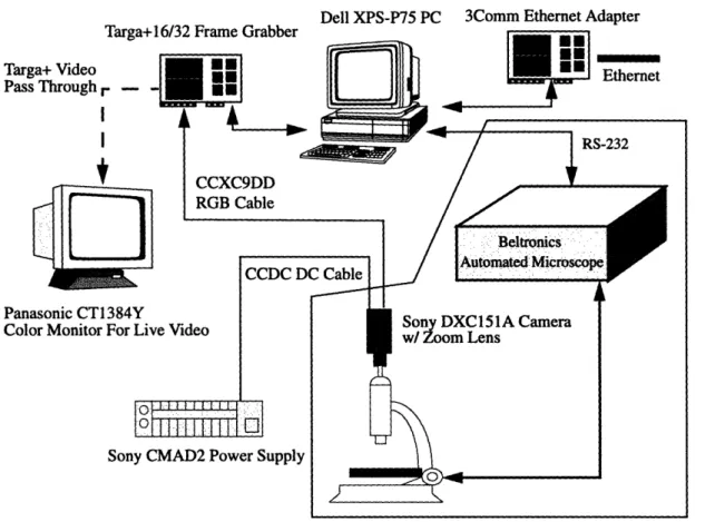
The current automated remote microscope system adds the automated microscope to the initial remote microscope system. The automated microscope includes the capability for the PC to automatically position, change magnification, and focus the microscope. The complete set up for the automated remote microscope is shown in Figure 8.
Although the cost of the automation of the microscope is the main cost, the cost of the entire system (which excludes the cost of the microscope) is in the order of $55,800. The cost of each component of the automated remote microscope is shown in Table 1. Because the automated microscope is only the prototype made specially for this automated remote microscope system, its cost is higher than it would be in the future. Other more economi-cal microscopes can be used as well as long as they provide the same serial interface and commands as the current automated microscope because the communication between the automated microscope and the microscope controller is well defined in the current system.
Dell XPS-P75 PC 3Comm Ethernet Adapter Targa+ Video
Pass Through
Panasonic CTI Color Monitor
FIGURE 8. Component setup for remote microscope. The components in the shaded area are added to the initial manual remote microscope.
TABLE 1. Approximated cost of each component of the automated remote microscope
hardware. The costs of all components except the automation of the microscope were for 1995.
Component Cost
75 MHz Pentium PC -$2100
Targa+ 16/32 Image Capture -$1800
Video Camera Equipment -$1900
Automation of the Microscope -$50000
Total (excluding the Zeiss Axiotron microscope) -$55800
Zeiss Axiotron Microscope -$30000
Total (including the Zeiss microscope) -$85800
,,, . , I z l - .
-r
I I
4.1 Automated Microscope System
We need an automated microscope system that has a computer interface so that the commands for the microscope can be ordered by a PC. The PC receives the user's request from the server and processes the request by sending commands to the microscope and receiving replies back when the microscope has finished the order.
For the current system, we have Beltronics build an automated microscope system. The Beltronics Automated Microscope System consists of a Zeiss Axiotron microscope equipped with computer controlled: X-Y stage, auto focus system, an illuminator, and an objective lens selector. One RS-232 interface is required to control the system, which con-tains the following hardware modules: power supply, X-Y-F axis motor controllers and drivers, an I/O card used to select and monitor position of microscope objective, and a programmable illuminator. The automated microscope provides commands for controlling the movement of the microscope stage, changing magnification, setting light intensity, and automatically focusing. The list of some useful commands provided by the automated microscope system is in Table 2. The resolution in X and Y directions is 0.4 microns, and in F direction is 0.1 microns. The current setting for RS-232 interface is at baud rate of
9,600, no parity check, and 2 stop bits [Be196].
TABLE 2. Commands for the Beltronics Automated Microscope System
Stage Commands Functions
calib s calibrate stage
halt stop all the motors
here define the current position
move move to specified absolute position
movrel move relative to current position
speed define final motor speed
status checks if motors are running
where returns position of axis
Focusing Commands Functions
focus I focus image using parameters optimized for 5x objective. focus m focus image using parameters optimized for 10x and 20x objectives.
focus h focus image using parameters optimized for 50x and 100x objective. fspeed defines focus axis motor speed when focusing
Idprdist transfers memory array data into focus hardware modulea rdprdist reads vertical distance parameters directly from focus module hardware
-TABLE 2. Commands for the Beltronics Automated Microscope System
Stage Commaands
Functions
sig f computes and returns value proportional to focus quality write focus array defines optimal focus parameters for each objective, specifically the
verti-cal distance between each focus position in focus profile, and stores param-eters in a memory array.
Turret Relating Com Functins
read IO0 check if 5x objective is in position
write o2=0 and then rotates turret to the next objective in direction of decreasing magnificationb write o2=1
write o3=0 and then rotates turret to the next objective in direction of increasing magnification write o3=1
Light Setting Functions
volt i read and set the intensity of the light
a. Ldprdist command requires a short time to update the memory in the focus module hardware. Thus, we cannot do read this memory immediately right after write into it.
b. To rotate multiple objectives, one must wait at least 1.2 seconds before issuing a next command to rotate turret to the next objective.
Although the automatic focus algorithm in the current microscope is implemented in hardware, it can be implemented easily in software running on the PC and might help to reduce the cost. However, the advantage of having in hardware is speed and simplicity. The future more economical automated microscope system might not need the auto focus hardware module.
Chapter
5
Software System Overview
The software architecture of the automated remote microscope is based on the archi-tecture of the initial remote microscope. The important additional part is the automated microscope controller module. Moreover, to be able to control the microscope a few more messages are needed between the clients, the server and the microscope controller.
5.1 Architecture of the Automated Remote Microscope System
The architecture of the automated remote microscope (Figure 5) includes multiple cli-ent units which run on UNIX workstations, a server process, a microscope controller, and a video module which grabs video frames. The last three run on a PC at the microscope site. More than one client can connect to the running server. Each client unitl consists of a Tcl/Tk user interface and a client daemon for processing binary data. The communication between the client user interface, the client daemon, the server, and the microscope con-troller is implemented by the CHAT message passing tools [Car95]. The communication of the video module and the server is a socket interface (like a pipeline).
1. In the future the client unit might be implemented in JAVA.
Client
iviessage interI e Functional Interface
N
FIGURE 9. Architecture of the Automated Remote Microscope System. The remote client units run on X terminals. The server, video module and the microscope controller module run on a PC at the microscope site.
The reason for this architecture is simplicity because we already have the initial remote microscope working. Thus, we add the automated microscope controller which replaces the attendant who manually controls and adjusts the microscope for the initial version. The video module is attached to the server since after the attendant manually pan the stage and change magnification, the server is notified and then asks the video module to grab a frame from the video camera. Therefore, the easiest and most effective way to add the automated function is to make a microscope controller module connected to the server by the CHAT messaging interface. The server's main responsibility here is to keep records of clients and of who is in control of the microscope. It can relay messages from a client to other clients as well.
This architecture is not what I had in mind at the beginning. At first, I thought that
,,Ai
Nl
the microscope controller module would include the video module as its submodule. This was because at first I thought that the controller had to implement the autofocus algorithm in itself and thus had to be able to grab multiple frames of the microscope easily and quickly. For an autofocusing, the controller moves the stage to different F-position, calcu-late a measure of focus quality of the image at that position, then repeats moving and cal-culating the focus quality until it gets to the optimal focus point. However, since the autofocus algorithm is already in the automated microscope hardware, we can use this one instead and simplify the programming of the microscope controller. Including the video module in the controller module would not be much harder because we just need to move the interface already in the server into the controller instead. If in the future we want to develop our own autofocus algorithm, the video module might need to be packed into the controller module.
Actually, it should be noted that the server need not be located on the PC at the micro-scope site because all the interface between the micromicro-scope controller and the video mod-ule is implemented by TCP/IP socket interface. Although the interface between the server and the video module is not CHAT message passing, it is connected by TCP/IP socket. Thus, the server can be located anywhere in the internet network. In some cases, it might be desired that the server be separated to be located elsewhere. For example, when the microscope is located at MIT, while most clients are in California. Having the server located in California, near most of the clients, will save network delay time to send images from the server to all the clients.
5.2
Microscope Controller Module
When a request for a frame capture at new position and magnification from the user of the remote microscope arrives at the server, the request will be relayed to the microscope controller. Then the controller interprets the request and calculates the sequence of com-mands which will be sent to the automated microscope to move the microscope stage to the requested position and to rotate the turret to the requested magnification. The micro-scope also does the auto focusing if requested. After the micromicro-scope has reached the new position and magnification, the microscope controller sends message to the server to notify that the server can initiate a frame grab from the video camera now. Then the server
will notify the video module to grab a microscope image, convert the image to GIF for-mat, and return the image to the server. The server then returns the GIF image to the user. At this point, one operation of frame capture is thus completed. The structure of the micro-scope controller module and the relation of the controller, the server, and the video module are shown in Figure 10.
L
Micl
clients
FIGURE 10. Microscope controller module in relation with the server and the video module.
The microscope controller module can be represented as three components: Function Translator, Safety Check Filter, and the Automated Microscope. The function translator translates the received request for the new position, magnification, and method of focus from the microscope server into a series of microscope commands such as move the stage, change magnification, and do auto focus. Before these series of command be carried out by the Beltronics automated microscope, they must be checked by the safety-check filter
to avoid possibility of crashing the objective to the wafer. The limit on the F-coordinate of the new position is also checked by the safety-check filter. The commands are sent from the safety-check filter to the automate microscope via the RS-232 interface.
5.3
Additional Messaging for Automated Remote Microscope
The backbone of the communication between the client, the server, and the microscope controller programs is the message passing built into the CHAT communication tools. It is very easy to use the messaging interface to integrate the different programs in the remote microscope system [Car95].
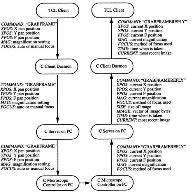
The current automated microscope system only modified and added a few more mes-saging to the "manual" remote microscope version. The modified and additional messages (Table 3) are relating to request to grab a frame into either windows ("GRABFRAME" and "ZOOMGRAB") and to request to load and calibrate a new wafer ("LOADNEWWA-FER" and "CALIB"). For details of the initial messaging that are still in use in the current automated version (see [Kao95] section 6.6).
TCL CLIENT -TO
-DAEMON-TO-SERVER-TO-MICROSCOPE DAEMON - TO - TCL CLIENT
COMMAND: "GRABFRAME" COMMAND: "GRABFRAMEREPLY"
XPOS: X pan position XPOS: X pan position
YPOS: Y pan position YPOS: Y pan position
FPOS: F position FPOS: F position
MAG: microscope magnification setting MAG: microscope magnification setting FOCUS: method of focus (auto or manual) FOCUS: method of focus (auto or manual)
COMMAND: "ZOOMGRAB" COMMAND: "ZOOMGRABREPLY"
XPOS: X pan position XPOS: X pan position
YPOS: Y pan position YPOS: Y pan position
FPOS: F position FPOS: F position
MAG: microscope magnification setting MAG: microscope magnification setting FOCUS: method of focus (auto or manual) FOCUS: method of focus (auto or manual)
COMMAND: "LOADNEWWAFER" COMMAND: "LOADNEWWAFERREPLY" XPOS: X pan position
YPOS: Y pan position FPOS: F position
COMMAND: "CALIB" MAG: microscope magnification setting DOIT: do calibration or not. FOCUS: method of focus (auto or manual) TABLE 3. Additional and modified Message formats used between Tcl/Tk Client and Daemon.
The "LOADNEWWAFER" request prepares the microscope stage for manually load-ing a new wafer. Then the "CALIB" request initiates the calibration of the new wafer. After calibration is done, the image of the new wafer at the middle of the stage and at the lowest magnification is returned with the "LOADNEWWAFERREPLY" to the user's win-dow A.
When the user sends a request for frame capture or loading a new wafer to the server program, the server relays it to the microscope controller program. After the controller has finished preparing the microscope for next frame capture, it sends a reply back to the server which then uses the video module to grab a frame and converses it into a GIF for-mat image. Then, the server packs the image into the reply sent from the controller. This reply will be sent to the client C daemon who saves the image into a file for the TCL client to read and display. The rest of the reply is sent to the TCL client. An example of the mes-saging between each programs for the "GRABFRAME" request is shown in Figure 11.
TCL Client
COMMAND: "GRABFRAME" XPOS: X pan position
YPOS: Y pan position FPOS: F pan position MAG: magnification setting FOCUS: auto or manual focus
C Client Daemon
COMMAND: "GRABFRAME" XPOS: X pan position
YPOS: Y pan position FPOS: F pan position MAG: magnification setting
FOCUS: auto or manual focus
C Server on PC
COMMAND: "GRABFRAME" XPOS: X pan position
YPOS: Y pan position FPOS: F pan position
MAG• mrninficatinn ePtting
FOCUS: auto or maanual focus
TCL Client
COMMAND: "GRABFRAMEREPLY" XPOS: current X position
YPOS: current Y position FPOS: current F position MAG: current magnification FOCUS: method of focus used TIME: time when is taken CURRENT: most recent image C Client Daemon
)
COMMAND: "GRABFRAMEREPLY" XPOS: current X position
YPOS: current Y position FPOS: current F position MAG: current magnification FOCUS: method of focus used SIZE: size of image
IMAGE: vector of image bytes TIME: time when is taken
CURRENT: most recent image ,r on PC
C Serve
COMMAND: "GRABFRAMEREPLY" XPOS: current X position
YPOS: current Y position FPOS: current F position lMAG d. mnafiri iUrrIJ
MA:CrUc:
FOCUS: n
LerIL IIncg llcatIon method of focus usedC Microscope C Microscope
Controller on PC Controller on PC
FIGURE 11. Example of messaging between each programs for the "GRABFRAME" command which requests to grab a new image at the new pan position and magnification with automatic focus or manual focus.
L
C Server on PC )
t
Chapter 6
Important Features of the Current Automated Microscope
This chapter will describe some important features of the current automated micro-scope that constrains how and under what conditions the micromicro-scope can move and rotate the turret safely and fast. The microscope controller which includes mainly of the move-ment algorithm for the microscope will be described in the next chapter. Thus, this chapter describes the features of the Beltronics Automated Microscope System that are the con-straints or limitations to the movement algorithm of the microscope. These features are the built-in automatic focus algorithm, offset between a pair of objectives in the focus posi-tions, depths of focus of each objectives, and the built-in safety mechanism.
6.1 Built-In Automatic Focus Algorithm
Because all algorithms relating to safety implicitly trust the autofocus algorithm to move the microscope stage to the correct optimal focus position, the autofocus algorithm is very important for the safety of the microscope. Although at 5x and 10x there is a mechanical stop that protects the wafer, at other objectives only the correct focus position ensures that the objective does not crash the wafer.
The autofocus algorithm depends on how the focus quality of an image is measured. When the microscope is at the "optimal" focus point, the image looks the sharpest. As the
we can invent a measure of focus quality as the contrast of the image. The plot of focus quality as a function of focus axis position will have a maximum at the optimal focus posi-tion. If the measure of the focus quality is accurate, the image at the optimal focus position must looks in focus to our eyes as well.
In the current implementation, the autofocus algorithm is implemented in the hardware of the automated microscope. The focus quality at a given vertical stage position is calcu-lated by high pass filtering the video signal to detect edges and integrating the output of the high-pass filter within a window which has the size of two third of the video image for 100 video frames [Bel96].
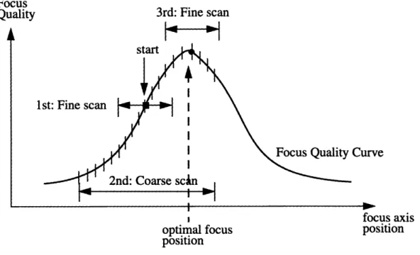
Basically, the autofocus algorithm is as following: from the starting F-position, the stage lowers by a half of the search range and then takes incremental steps up for the spec-ified number of steps. At each step, the focus quality is measured and a focus quality pro-file is generated. The propro-file is examined to determine if a local maxima exists. If it does, the corresponding F-position is used as the optimal focus position. If a maxima does not exist the scan range is increased to encompass a larger distance. The smaller scan is called "fine scan" and the wider is "coarse scan." If there exists a local maxima in the coarse scan, a fine scan is performed between the two coarse positions surrounding the maxima. The maxima located in this second fine scan is the optimal focus position. If no local max-ima is detected in the coarse scan, the algorithm is aborted.
The number of steps in a scan and the ranges of the fine and coarse scan must be opti-mized and must be optiopti-mized for each lens of the microscope because low magnification lenses, such as 5x objective, have a much larger depth of focus than high magnification lenses, such as the 100x objective.
An example of a search for optimal focus position is shown in Figure 12.
FIGURE 12. Plot of Ideal Focus Quality as a function of focus axis position
Focus
Quality 3rd: Fine scan
Curve
IOcus axis
optimal focus position
position
When the current automated microscope is asked to do an autofocus, it does not return the result whether the autofocus attempt is successful. It only moves the stage back to the starting position if the autofocus cannot find the local maxima within the coarse scan. Hence I implemented the way to detect the result of the autofocus by after the autofocus is done1, the focus quality is calculated by the "sig f" command at the current position, a lower F-position, and a upper F-position. If the focus quality at the middle point is the maximum among those at the three points, the autofocus execution is assumed to be suc-cessful. This is in a way finding a local maximum by using three samples on the focus quality curve. Because it takes time to move the stage and wait before measuring the focus quality, I use only three samples which should be sufficient. It would be faster and easier if the autofocus algorithm in the hardware returned the result of autofocusing because it has already known the focus quality profile. The positions of the lower and higher samples depend on the depth of focus for each magnification.
For the low magnification such as 5x, 10x, and 20x, there is enough room between the
1. It is checked by detecting if the stage stays in the same F-position for at lest 60 milliseconds.
45
jL i' 'I
Is