HAL Id: hal-03086730
https://hal.archives-ouvertes.fr/hal-03086730
Submitted on 23 Dec 2020
HAL is a multi-disciplinary open access
archive for the deposit and dissemination of
sci-entific research documents, whether they are
pub-lished or not. The documents may come from
teaching and research institutions in France or
abroad, or from public or private research centers.
L’archive ouverte pluridisciplinaire HAL, est
destinée au dépôt et à la diffusion de documents
scientifiques de niveau recherche, publiés ou non,
émanant des établissements d’enseignement et de
recherche français ou étrangers, des laboratoires
publics ou privés.
Current-driven electromagnetic ion cyclotron instability
at substorm onset
S. Perraut, O. Le Contel, A. Roux, A. Pedersen
To cite this version:
S. Perraut, O. Le Contel, A. Roux, A. Pedersen. Current-driven electromagnetic ion cyclotron
in-stability at substorm onset. Journal of Geophysical Research Space Physics, American Geophysical
Union/Wiley, 2000, 105 (A9), pp.21097-21107. �10.1029/2000JA900059�. �hal-03086730�
JOURNAL OF GEOPHYSICAL RESEARCH, VOL. 105, NO. A9, PAGES 21,097-21,107, SEPTEMBER 1, 2000
Current-driven electromagnetic ion cyclotron instability
at substorm
onset
S. Perraut, O. Le Contel, and A. Roux
Centre d'ttude des Environnements Terrestre et Planttaires, CNRS/UVSQ, V•lizy, France A. Pedersen
Department of Physics, University of Oslo, Oslo, Norway
Abstract. ULF waves at frequencies of the order of the proton gyrofrequency are systematically detected at the early development of substorm breakups. The observed characteristics of these
ULF waves,
namely
their polarization
and fiE/fiB
ratio are consistent
with being
electromagnetic
waves driven unstable by a parallel current. In order to take into account properly wave particle interactions, a kinetic approach is used. We show that a parallel drift between electrons and ions leads to a strong instability, resulting from a coupling between the shear Alfvtn (SA) mode and the fast magnetosonic mode via this drift. We call it current-driven Alfvtn instability (CDA). We have carried out a parametric study of this current-driven electromagnetic instability in a
parameter range adapted to conditions prevailing at the geostationary orbit before and during breakup. We conclude that even a modest parallel drift between electrons and ions (Vd), caused by a parallel current, can alestabilize CDA waves. When the ratio between Vd/V A (V A being the Alfvtn velocity) increases, the CDA mode couples with SA mode. These two modes have a substantial parallel electric field that leads to a fast parallel diffusion of the electrons. We suggest that this parallel diffusion leads to an interruption of the parallel current.
1. Introduction
The signature on particles instruments and fluxgate magnetometer of a substorm with dispersionless injected
particles, occurring while the European geostationary spacecraft GEOS 2 was close to the magnetic equator, has been described by
Roux et al. [1991a, b] and ?erraut et al. [1995]. These studies provide evidence for the formation of thin current sheets, even as close from the Earth as the geostationary orbit [Lui et al., 1977].
Similar observations have been carried out on AMPTE/CEE by
Lui et al. [1992]. For the present study we have selected one substorm event: January 25, 1979 (a detailed description of field and particle measurements for this event is given by Roux et al. [1991a, b] and Perraut et al. [1993]) that occurred while GEOS was 3 ø off the geomagnetic equator. In addition to particle and fluxgate magnetometer measurements, we use wave
measurements from the electric field instrument and from the
low-frequency triaxial search coil magnetometer. Robert et al.
[1984] have already pointed out that large-amplitude
electromagnetic fluctuations are observed at substorms with most
of the energy being below FH+, the proton gyrofrequency. The frequency range, howewer, largely exceeds FH+. In this frequency
range one expects to find fast magnetosonic (FMS hereafter) waves and therefore expects the polarization to be right- handed/compressional (depending on the direction of the wave normal) and the 1•SEI/I/SBI ratio to be of the order of the Alfvtn
Copyright 2000 by the American Geophysical Union. Paper number 2000JA900059.
0148-0227/00/2000JA900059509.00
velocity
VA
(more
precisely
Vn•-•[)-•Fa+)
:r, where
F is the
emission frequency). Pertaut et al. [1993] found that the polarization characteristics and the 1tSEI/ltSBI ratios are not consistent with the waves being FMS waves. One possibility, put forward by Perraut et al., is that the mode is the intermediate mode studied by Formisano and Kennel [1969] with a bifluid approach. Yet the bifluid approach is not necessarily valid especially at and above F,•+, then a kinetic approach is needed to resolve this issue. Given that the observed waves are strongly related to breakup and could therefore play a role at triggering substorms, we have carded out a more detailed study with more refined tools, in particular we use the kinetic theory to identify the modes and reanalyze GEOS 2 data.
In section 2, we present the main observations underlying the present study; we characterize waves around F•,+. Section 3 describes the solutions of the dispersion relations of low- frequency waves in a large 15 plasma (15 is the ratio between the kinetic and the magnetic energies, ~1) obtained with a kinetic approach. We have chosen a set of parameters that describe the plasma conditions encountered in the plasma sheet. We show that the presence of field-aligned electrons leads to the development of a strong instability resulting from a coupling (via electrons drifting along field lines with respect to ions) between the FMS mode and the shear Alfvtn (SA) mode. In section 4, the kinetic theory is used for a parametric study of this electromagnetic current-driven instability. The results obtained for different drift velocities, and magnetic field amplitudes (or 15) are compared with observations. Section 5 is devoted to the coupling between the electromagnetic current-driven instability and the SA mode. Finally, the propagation of the waves along the field lines is briefly discussed, and a scenario is proposed to explain the role that these waves could play at substorms.
21,098 PERRAUT ET AL.' CURRENT-DRIVEN ION INSTABILITY AT SUBSTORM ONSET 2. Characterization of the ULF Waves Observed at
Substorms and Free Energy Source
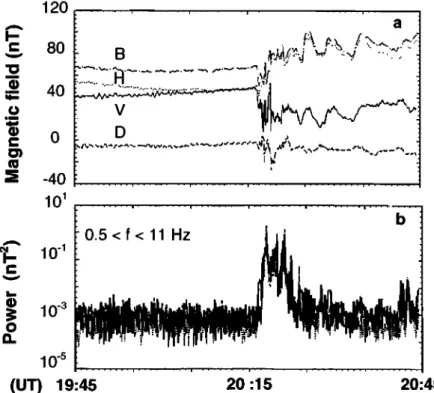
The selected event corres[x)nds to dispersionless injection of energetic elecmms and ions. The lack of energy dispersion (not shown) suggests that the acceleration is a local process. The three components V, D, and H of the dc magnetic field B. displayed in Figure l a, give key intbrmation about the magnetic configuration. A large V component (in this case V=H prior to breakup) indicates that a thin current sheet has developed and that GEOS, though being close to magnetic equator, is not at the center of this current sheet. The increase of the H component is a clear indicator of the dipolarization of the B field. The integrated [x)wer of the magnetic fluctuations up to 10 Hz are also displayed in Figure 1. A detailed analysis of the spectra of the electric and magnetic components of the Pil has been reported by Perraut et ai. 11993l tk•r this event. These waves have a broad band spectrum observed in the same frequency range as Pil oscillations observed on the ground IHeacock, 1967, Biisinger et ai., 19811. Figure 1 shows (1) that while the dipolarization develops, -1 rain period oscillations (identified as ballooning modes of the thin current sheet [Holter et al., 19951) with periods in the Pi2 range superiml•)se on the quasi-do increase of H and (2) that higher~
frequency transient fluctuations (F~ F,+) develop simultaneously
in the Pil range. The occurrence of waves in the Pil range is a salient feature of substorm breakup. This is regularly observed, at least for dispersionless injections events ]Perraut et ai., 1998 I.
The /k)rmation of thin current sheets during substorm growth phase has been studied by Le Contel et al. [1998, 2{XX)I. It has been shown that time variations associated with the fi•rmation of a current sheet impose, via the quasi-neutrality, a field-aligned
electric field. Such an electric field will accelerate electrons along the field lines, either equatorward or toward the ionosphere, depending on the ltxzal time variation of the perturbation iml•)sed by the solar wind and on the direction of the pressure gradient. This parallel electric field can produce the free energy source that drives waves unstable. The parallel potential drop found by Le Contel et al., is of the order of I(X} V. There is a parallel current asstx:iated with this parallel electric field; the corresponding drift velocity between electrons and ions should be of the order of a t•w 1½) • m/s, which is difficult to measure. Whenever a sufficient pitch angle coverage was available, field-aligned electrons were found together with waves IShepherd et al., 1990; Perraut et al., 19981. at breakup. This suggests that field-aligned low-energy electrons are related to the intensification of the ULF waves. Similar observations have been made by Johnswne et ai. 119941, who have also observed field-aligned bursts of electrons in the low energy range, often associated with changes in the configuration of the magnetic field. These intensifications were found by Johnswne et ai,. to be generally bidirectional. but fluxes depend on the latitude of the spacecraft and are not the same in the parallel and antiparallel directions: hence there is a current. These observations and the corresponding increase in the field- aligned electron flux are consistent with the presence of a field- aligned drill of elecm)ns with respect to ions that can drive waves unstable. Motivated by these results, we have solved numerically the full electromagnetic, linear dispersion relation for Mawellian electrons streaming with a drift velocity V,, (along the magnetic field B) with respect to Maxwellian ions, in a homogeneous, infinite Vlasov plasma. Like Gary. et ai. [19761 and Forslund et ai. [ 19791. we are considering a finite 13 plasma.
120 I::: 80
ß
-•
40
c:
0
-4010 •
A
0_.
•
0-3
10 -5
0.5<f<
1Hz
'
! 'ß
_(UT) 19:45
20 '15
20:45
Figure 1. (a) V, D, and H components (V is radial from the Earth, D is azimuthal, and H orthogonal to V and D) and total dc magnetic field B. (b) Integrated power of B components of waves around F,+, between 0.5 and 11 Hz. All
these parameters have been measured on GEOS 2 on January 25, 1979. Notice the simultaneity between the
occurrence of the "high-frequency waves" around the proton gyrofrequency, the fluctuations of the dc magnetic
PERRAUT ET AL.' CURRENT-DRIVEN ION INSTABILITY AT SUBSTORM ONSET 21,099
3. Electromagnetic Current Driven Instability
Electrostatic current-driven instabilities have been extensively studied fi)r very low 13, a situation that applies to the ionosphere. For instance, Kindel and Kennel 119711 have studied the tx•ssible role of ion acoustic/ion cyclotron waves driven unstable by electrons drifting with respect to ions.In the equatorial region where our observations took place. the parameter 13 is typically ~1. Gary and Forslund [19751. Gat'), et ai. [19761 and Forslund et al. [19791 have shown that. in a large 13 plasma, the usual current-driven instability (see, for instance, Drummond and Rosenbluth 11962]) is modified. As soon as
13>m/m,. a new electromagnetic instability is found. with a velocity threshold comparatively (i.e., in terms of the ratio V,.•/V•) lower than the corresponding electrostatic instability. Thus. even a modest drift of electrons relative to the ions (along a dc magnetic field) may excite waves around the ion gyrofrequency. with a finite magnetic coml•)nent.
In view of the observations described above. the electromagnetic current-driven instability is a gtx)d candidate to account for wave observations. We have solved the kinetic dispersion relation with a software (WHAMP) designed by R•hmmark [19821. for a set of parameters that fits the observations. The density is 1 cm. the magnetic field is 50 nT (giving F,+-0.76 Hz and V,,~I.I(X) km/s), and the plasma is composed of two populations, ions and electrons with MaxwellJan distributions and a thermal energy of 12 keV for the ions, and 2 keV for the electrons (T,/T•=6, typical for the plasma sheet). In these conditions. 13- 1. Since the parallel propagation (0=0 ø) has been already studied by Gary et al. [19761. oblique propagation (0=45 ø) is mainly considered in this work (0 denotes the angle between the wave vector and the magnetic field). The effect of a differential drift velocity between the ions and the electrons is studied by comparing the solutions with those obtained in the simple case where there is no drift.
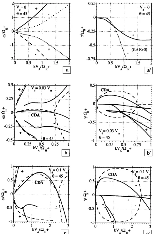
Figure 2 displays the dispersion relation t•)r V,,•=(}, 0.03 and (). 1 V,, (where V,, is the thermal velocity of the electrons: thus V, corresponds to O, 2, and 20 eV. respectively) and for 0=45 ø. The frequency •2•:, normalized to the proton gyrofrequency and the normalized growth rate ht/f•.+ are plotted as functions of the normalized wave number K=kV,/f•.+. Similar solutions have been obtained by Gary et al. 119761 for 0=0 ø with a different ratit) T,/T• (=0.5 in their case).
For Va =0 one gets four solutions: two branches with positive frequencies corresponding respectively to FMS (labeled plus) and SA (labeled minus), while for negative frequencies: (plus) corresponds to SA and (minus) to FMS. The notation (plus or minus) is the same as in the work of Gary et al. 119761. the reason for its use will be clarified later. The SMS mode is damped to be followed. Comparison between Figure 2a and the Figure 1 from Gary et al. [19761 shows that the variation of the frequency of the SA mode as a function of K, strongly depends on the propagation angle. With our set of parameters and for parallel propagation (not shown) the normalized frequency reaches a maximum around 0.25 for K~0.9, while for 0=45 ø (Figure 2a) the frequency monotonously increases with K, as expected for the intermediate mode in a high 13 plasma and for oblique propagation [Formisano and Kennel, 19691. All modes are damped when Va =0 (Figure 2a').
As soon as a small parallel drift of electrons relative to the ions is introduced an instability with a large growth rate develops (see Figures 2b, 2b', 2c and 2c') for 0=45 ø and Figure 2 in Gat3, et al. [ 19761 for 0=0ø). Again, the behavior depends on the propagation angle:
1. For parallel propagation, in a warm plasma. the number of solutions does not change {Gary et al., 1976, Figure l i: the frequencies of solutions labeled plus are slightly modified with respect to the case V,, =0, while solutions labeled minus have a very different sha•; they are no longer symme•ic with res•ct to the other r{x•ts. and merge t•r small K (kpt<().3). This merged branch and the adjacent branch with a •)sitive frequency, t•,r 0.3< kp,<l, exhibit a large positive growth rate (Figure 2 of et ai. 119761).
2. For oblique propagation one gets solutions that ltx)k like the
case Kt =0 and 0=45 ø (see Figure 2 ), but there is a striking
difference: the ap•ance of a new root at low frequencies with a large •sitive growth rate. Hereafter we will call the branch with a •sitive growth rate T: CDA, standing for current-driven Alfv6n wave. To identify the nature of the corres•)nding instability. we will comp•e the kinetic solutions to an analytical approximation obtained in the bifluid approach.
The current-driven electromagnetic instability has also •en studied by Hasegawa 119751. A general dispersion relation is given by his formula (2.5()). As the dis•rsion relation is not solvable analytically in the general case. we have considered a simple situation where ions are "cold" and station•y whereas the electrons am hot with their thermal vel{•ity much l•ger than the phase velt•ity and drift at a velocity V• with respect to the ions. Thus the ions can be represented by the delta thnction and we can assume a drifting Maxwellian distribution for the electrons. If we choose a coordinate system fixed to the ions the dis•ibution functions in the p•allel direction are given by
f'" = •(V...) o II
where V::, and Vz, •' •e the p•allel thermal vek•ities of ions and
electrons. Thus the two dispersion relations D+ and D- for p•allel propagation write:
'
{) (l)
I 2 ((0-
kV,,
)
f•
2•,,
co
D-:
k2c
2
_(02
_ (0•,,•
kV,
e Z,(•')
+
0 (2)
where the arguments •.2 of the plasma dispersion function Z•.2
[Fried and Come. 1961 ! •e
f•p,,
t0•.,
f•,,+ and
•.•, are the ion and
electron
plasma
frequencies
and proton and electron gyrofrequencies. respectively. The sign (plus or minus) in front of f•,+ in the denominator of (1) and (2) are used to label the various curves by comparison with the analytical results.In the plasma conditions under consideration co<<m.,, thus. as
long as k<<co,.,11, 5, •1,2 >>l. and the asymptotic expansion of Z(•)
leads to
D+:
k2c
2 (0
-2
+W•,e
((0-k,V•) 2 0
' + f•,, • = 0 (3) (0- k , V • -(0 • ce ro + f• H +D- k-'c:
' -(02
+(0),•
((0-k,V,) , to
' + f•j,, • = 0. (4)(0
- t•
. , V
, +(0.
A tbrmula similar to (4) is given by Hasegawa [1975]. At low
frequency.
for parallel
propagation
and for fIp./fI.+>>l, these
expressions become21,100 PERRAUT ET AL.' CURRENT-DRIVEN ION INSTABILITY AT SUBSTORM ONSET 0 0.5 1 1.5 2 kV/f• +
0=45 [
0 ... :;; ... : ...
i
...
+G-,
= -0.25
...
ß:
...
: ...
-0.5- •' '•. (fo• F>0) -0.75 .... .... ;•,..., .... 0 0.5 1 1.5 2 kV/f• +:
/
_+.=
iI
..i.
- _ ..i.. '!
•
0 ....
-'•:---•----:
... •.--•--- /: ...
q. i
i
0 0.25 0.5 0.75 kV/f• +^ .
4- •= 0 ' ! V=0.03 V : d ' te 0=45! =1 ' 0 0.25 0.5 0.75 1 kV/• + 1+ 0.5
0 1 2 3 kV/• + 0.5-Figure
2. Warm
plasma
dispersion
relations
for
(a,
a') V•0, (b,
b') V•O.O3V,
e,
and
(c,
c') V•0.1V,e,
for
oblique
propagation
(0=45ø).
The
normalized
fre.quencies
•fl.+ and
normalized
growth
rate
),/fl.+
are
plotted
versus
normalized
K, defined
as K=kVA/I2.+.
B=50
nT, T?12
keV,
T•=2
keV,
N,=N•=I
cm
'3,
B=8•NKBT/B
2 -1. Two
symmetric
couples
of waves
are
found
for V•0: For
positive
frequencies,
plus
is the
FMS
mode,
minus
is the
SA
mode.
In Figures
2b, 2b',
2c,
and
2c',
the
solid
curves
correspond
to the
kinetic
solutions
and
the
dashed
curves
are
the
solutions
of the
approximate
equations
(5') and
(6').
A new
branch
called
CDA
mode
is strongly
amplified
for
V•0.03
V,,
and
for V•=0.1V,,.
Notice
the
substantial
positive
growth
rate
for the
CDA mode.
The
other
modes
have
a
negative
),/I2.+.
The
approximation
provides
a relatively
good
determination
of the
CDA mode
for the
real
as well
PERRAUT ET AL.: CURRENT-DRIVEN ION INSTABILITY AT SUBSTORM ONSET 21,101
D+' X
z-
X(K•2•
+
K,•-•)-(K•2•
+
K,•-•)=0 (5)
D-
: X
2
+
X
(
K
,•-,
- K
, •-•
) - (
K
,
z,
-K,
V-•-)=0,
(6)
where K and X are the normalized variables defined above,
X=• f2.+ and K= k. V,/f2.+.
In the case of nonparallel propagation approximate formulas ((5') and (6') below) can be found. Equation (5') is deduced from
(5) by replacing
K//•
by K: in D+. One
can
verify
that
for V
d
=0 the
positive roots of D+ and D- correspond to the FMS and SA modes, respectively. Comparison with exact solutions shows the usefulness of the approximate formulas (5') and (6').
D+' X
•-
-X(K
• +
K,•df)-(K
• +K,v
•) =0 (5')
O-' X2+
X(K,
2,
- Kn
v•)-(K,2
, - K//
•) =0. (6')
Equations (5) and (6) have two solutions each. For 0=0 ø. the roots (plus) are weakly modified by the drift. and the solutions of (5) fit pretty well with the exact solutions given by Ga.rv et al. [ 1976]. The roots (minus), howewer, merge (complex conjugate) to give the CDA mode. Analytical solutions of (6) also fit the numerical ones [Gary et at, 1976].
For 0=45 ø, (5') and (6') also have two solutions each. Again, the roots (plus) (dashed lines) fit well the exact result (solid curves), as can be seen in Figure 2b, 2b', 2c, and 2c'. The roots (minus) also fit well with the numerical solutions at least for
K<0.75 (for V, =0.03V,•) and for K<2.5 (for V, =0.1V,•). The
number of roots found numerically, howewer, depends on Va. For small V d (V d =0.03) the "classical" SA mode found for Vd =0 is still present, in addition to the CDA mode (hence there are five roots for a given K). For larger V d the classical SA disappears (too damped).
Although the topology of the branches plus has changed, they can be identified by following the progressive deformation of the solutions with increasing Va and by comparison with the analytical expression. The approximation reproduces relatively well the shape of the real part of solutions + as well as the CDA mode. However while the CDA mode (which only exists in the presence of a drift) is strongly unstable, the classical Alfv6n mode and FMS modes are damped.
Let us now focus on the only unstable mode: the CDA mode. Given that the analytical expression describes relatively well this mode, we will use it to ease the discussion.
The discriminant intervening in the solution of (6') is null for four values of K: K,=0, K,=V,•/V, and
1Va
I 16Vn2
=
l-
).
When
V) > 16V,•
2, K,,,.
2 is real
and
the
wave
is unstable
in two
K,,
domains: O<K,,<K,,• and K,a <K,,< V•/V A which explains why the
growth rate can present two maxima for a set of parameters. Notice that positive growth rates are only obtained for K,, < VdlV A.
In the opposite
case where
V•
2 <16V,,
•, one can neglect
K/,(K/?Va/VA) with respect to 4. Thus an approximate solution of
(6') can be found; it writes
= g.(•-fn-g.)_+i -g..
(7)
The slope of the real part for small K, is OX/OK,? V, /2 V,, which gives in the (X, K,) frame (V• cos 0)/2V,, as can be verified from
Figure 2. Although (7) is approximate, it gives the correct
threshold in K,, namely the minimum V•IV A, for getting a positive
growth rate
The CDA mode identified in these conditions is an interesting new feature; while the classical FMS or SA modes are absorbed
('l'/f2.+
< 0), the electron
drift produces,
for small
K,,, a strong
instability; 'l'/f2.+ reaches -0.3, even for a low value of
(0.03
V,) corresponding
to a bulk
electron
energy
of-2 eV (Figure
2). We will now develop a parametric study of the role of the drift
velocity
Va,
of the magnetic
field
B 0 and
of the ion temperature
T,
on the frequency and the growth rate of the CDA instability.
4. Parametric Study of the CDA Mode
The propagation angle 0, the relative drift velocity between ions and electrons V,, and the Alfv6n velocity are the main parameters
in (6'). We have found that the frequency and the growth rate
depend very little upon the electron temperature; therefore the instability has a fluid type, a conclusion consistent with the approximate dispersion equation (6) obtained for parallel propagation. Thus the growth rate depends mainly on the drift
velocity of the electrons and not on the slope of the electron
distribution at least as long as V,<<V,e. Notice, however, that ions
are damping the wave that explains why a kinetic approach is needed. We study the behavior of the kinetic solution as a function of 0 and then solve the dispersion relation for selected values of 0 and for different V• and 13.
4.1. Effect of the propagation angle 0
Even without drift velocity between ions and electrons the
shape of the dispersion relation changes very much with 0. For
example, for 0>40 ø the frequency of the SA mode increases monotonously, instead of increasing until it reaches a maximum
(generally below F,+) and then decreasing as K increases.
Therefore it is interesting to study the modification of the
dispersion relation of the CDA mode as a function of 0 for a given drift velocity V, =0.2V,•, which corresponds to an energy of
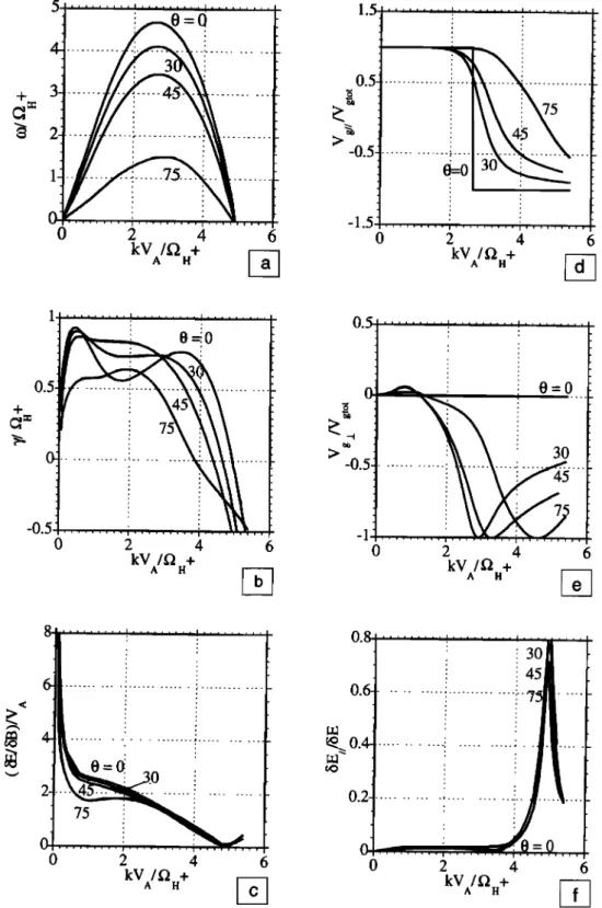
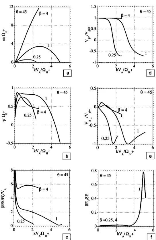
80 eV. Figure 3 displays the variations of a full set of parameters
characterizing the waves ((õElõB, bE,/õE ratios, group velocity...) for different angles of propagation. Figure 3a shows that for K<2
the reduced frequency depends linearly on K//, more precisely the
normalized phase velocity at low frequency is (V, cos 0)/2V, as
discussed above. The maximum frequency corresponds to
K-O.5V,/V A (.•2.4 for the set of parameters selected here). The growth rate has a more complex behavior (Figure 3b): for small propagation angles a relative minimum occurs between the two
maxima at K~2, as expected from the approximate solutions of (6'). This minimum however disappears for 0>40 ø. As a consequence, for oblique propagation (0-45ø), one expects to get a wide band spectrum coveting a frequency range >3F.+. For K<I and K>3 the growth rate decreases with 0. For 0-0 ø the mode corresponding to a maximum growth rate at small K is identified as "kink-like instability" by Gary et al. [1976], while
the mode corresponding to the maximum at large K is identified
as "whistler current instability."
The parallel group velocity is generally larger than the
perpendicular group velocity, at least for K<2.5 which
corresponds to the most unstable mode (compare Figures 3d and
3e). In the same range of K, the õE/fiB ratio is larger than the
Alfv6n velocity and does not depend strongly upon 0 (Figure 3c).
The parallel electric field is finite: bE,/-O.O2õE•. (Figure 3f), and sharply increases up to 0.8•5E for K-5, but this range of K
corresponds to values where the CDA mode is damped. Notice that for K-5 the group velocity has a nonnegligible perpendicular
21,102 PERRAUT ET AL.' CURRENT-DRIVEN ION INSTABILITY AT SUBSTORM ONSET .
0
2
kV /f2 +4
6
0
.... 2 ...
4
6
A .
•
kV
A/f•+ •
H1
0.5 ...
! ...
+ 0.5
0 0 .
0
2
4
6
0
2
4
6
kV/f• +
kV /f• +
A H
•
A H
•
1300.6
...
i ...
!'-75 ...
0.2;
...
! ...
i
...
0
2
4
6
0
2
4
6
kV/f• +A H
•
kV/f•
A H+
Figure
3. Normalized
frequencies,
growth
rates,
fiE/fiB
ratios
(compared
to
VA),
;SEJISE,
VgJVg
....
and
Vga./Vg,o
, for
the
CDA
mode
as
a function
of normalized
K for
a fixed
V
d (V•=
0.2
V,•),
13-1
and
for
different
propagation
angles.
The
other
parameters
are
the
same
as
in Figure
2; •f•.+ and
?/f•.+
are
maximum
for
0=0
ø,
and
the
wave
is well
guided
along
the
magnetic
field
for K<2 and
in the
opposite
direction
above
(K>2).
The
dispersion
relation
exhibits
a
maximum
frequency
at K~O.5VJVA=
2.4.
The
phase
speed
at low
frequency
is (Vd
cos
0)/2
VA.
component and that the fiE/fiB ratio vanishes. For 0=0 ø, there is
no parallel
electric
field
component
and
the
perpendicular
group
velocity
is null (as expected).
Since
the presence
of a parallel
electric
field is a critical
parameter
for studying
wave-particle
interactions,
we will carry
out
the
rest
of the
parametric
study
of
the dispersion relation (with WHAMP) for an intermediate
angle,
0=45%
corresponding
to a finite
E,.
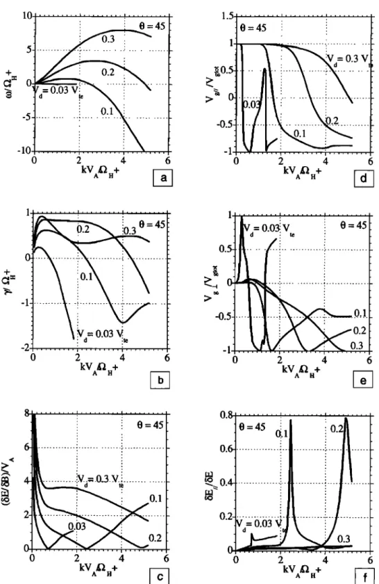
4.2. Effect of the drift velocity
The angle of propagation is now fixed to 45 ø , and four different
values of V• are considered in Figure 4. The larger the drift velocity, the higher is the emitted frequency (Figure 4a). When
the
drift
velocity
increases,
the growth
rate
becomes
large
over
a
wider
range
of K and
exceeds
0.8 for V• =0.2
V,•
(Figure
4b). For
PERRAUT ET AL.: CURRENT-DRIVEN ION INSTABILITY AT SUBSTORM ONSET 21,103
larger V a, for example, V a =0.3 V,,, the growth rate has two maxima
and is positive over a wide range of K. Notice that for an even
larger V d (V d > 0.5V,•, not shown here), the range of K corresponding to wave growth (positive ¾) reduces. A large drift
velocity (V a > 0.1) destabilizes frequencies below and above the proton gyrofrequency. We have found that the CDA mode is LH
polarized and strongly compressional whatever V a and 0. The
larger V a, the larger is bE/fiB (Figure 4c); for instance, bE/bB=3
for K=3 and V a =0.3V,,. The wave is well guided along the dc magnetic field for different ranges of K depending on V a (Figure
4d), for a small
K: k, Vg
>0, while
for high
K (K> 5): k, Vg<0.
For
intermediate values of K the group velocity is oblique; when Va=0.2V,• the wave is well guided over a wide range of K, up toK<2 (Figure 4d). The bEJbEratio (Figure 4f) reaches -0.02 for
1 0 2 4 6 kV12 + 1.5 1
>• 0-
-0.5'
-1 0 0=45 _ 3V . 2 4 6 kV12 + i ... i ... i • , , i , , , , , i ].
45
E
o.5'.
•" -1
....
i
...
-0.5--2 ... ! ... ...
0 2 4 kV12 + A H 6Va=
0.03}
V,e i 0=45
...
:
0.1
'
0.2
, 0 2 4 6 kV12 +^.
1 I 0=45:
02
0=45 (•.1
;0.2
, , :. . , ,0.•
0.2
...
i
....
0 2 4 6 0 2 4 6kV12
A H+ •
kV12
A H+ •-•
Figure 4. Same as Figure 3, for 0 fixed (0=45ø), and 13-1, for different drift velocities Vd between ions and electrons. ogf•.+, 'y/f•.+ and bE/bB increase with Va. The range of K where ¾ is positive also increases with Va. Notice that bEJbE =0.02 over the unstable range of K. See text for discussion.
21,104 PERRAUT ET AL.: CURRENT-DRIVEN ION INSTABILITY AT SUBSTORM ONSET
l<K<4 and sharply increases above 0.7 for K~2.5 (for V d = 0.1V,e) and 5 (for Vd = 0.2 V,,). These large increases occur near the value of the K, corresponding to the marginal stability.
4.3. Role of the plasma parameter g
During substorm growth phase the intensity of the magnetic field can change by a factor of 2-3 near the equator, in the near-
Earth plasma sheet (NEPS) (see, for example, Figure 1, where B o
is -50 nT, whereas its typical value is 100 nT at the geostationary orbit). Furthermore, B 0 increases along the field line, which has to be taken into account for studying wave propagation along the field lines. Then it is very important to consider the modification of the dispersion relation as a function of B 0 (or 13), and to keep the density constant. Figure 5 displays the corresponding results. The reduced frequency (Figure 5a), the growth rate (Figure 5b), and the bE/bB ratio (Figure 5c) increase when 13 increases (or B 0
12
1.5
...
0 45i !• ' 4
+
o.54
...
i ...
-X
...
!
...
•
>• 0 ...
-0.5
0 2 4 6 0 2 4 6kV
A/f2
H+
•
kV
A/f2
H+
•
I i ... i ... 1 , ,:i 0=45
•" 0
-O.5 • 0 2 4 6 kV/•2 +0'5
i
0-4
:>-0.5•
i 1 '
-1 ,,,,,,,,, , , , , , , , , , 1 0 2 4 6 kV /• + .<0=45
2'---
':
...
}
,,,.... ... i ... 0 2 4 6 kVll + 0:45 ' . ,0.6
...
! 1 ...
0.4-
l
0.7.
.... i ...
. 0 2 4 6 kV/•2 + A HFigure 5. Same as Figure 3 for 0 fixed (0=45 ø) and VA= 0.2V,,, for different plasma parameters 13. When 13 increases
(B o decreases), oYf2.+, ¾/f2.+ and bE/fSB are increasing. The range of K where the wave is well guided is reduced
PERRAUT ET AL.: CURRENT-DRIVEN ION INSTABILITY AT SUBSTORM ONSET 21,105 0.4 0.3 ÷
0.2-
0.1 •,
Vd= .07
Vex
=45s^rx,
I I I 0 0.5 1 1.5 kV,• + A H 2 0.4 0.3•0.2
•
0.1 0 0:
:
0.064
DAw-/---•
I...
r '- • '' r
I I [ I I I 1-.... i .... i .... l .... i
0.5 1 1.5 2 kVll +ß Vd=
0.055
Vte
0.3.
S-t/ 0=45
•=: 0.2-
0.1 .... , o• o 0.5 1 1.5 2 kV/f• + 0.5 -0.5 -1 o 0.4 0.3 o. 1 o o (•DAW _Vd•
0.064
V
t
,0=45 i I ! I ... -1 ... 1_ .... -4 ... I I I Is^ ',
i I I.... I .... i .... I ....
0.5 1 1.5 2 kVl'2 +A .
Vd=,0.064
Vt,
'
i i • 0=45 I I I....
, i i i i ' ' ' i , , , i , , , i , , , 0.5 1 1.5 2 kVl'2 +A .
Figure 6. (a, b, c) Dispersion relations of CDA and SA modes for 0=45 ø and for slightly different V d (Vd cos 0 -VA). The other parameters are the same parameters as in Figure 2. (d) Growth rate and (e)parallel electric component for
V•= 0.064V,
e, corresponding
to the electron
drift velocity
when
the two modes
couple.
Notice
the strong
parallel
electric component of the SA mode.decreases for a fixed temperature). Thus the decrease of the magnetic field associated with the building up of a thin current sheet is especially favorable for getting waves with high
frequencies (above F.+), large growth rates and large fiE/fiB
ratios. Moreover a high 13 gives a wider range of K with large parallel group velocities (Figure 5d). As seen previously,
the 15E,fiSEratio reaches -0.02 for a wide range of K and
maximizes just below the frequency for marginal stability (Figure 5f).
5. Coupling Between CDA and SA Modes
The CDA mode is well guided along the magnetic field at least for low values of K. During their propagation toward the
ionosphere the CDA waves will encounter a region where
Va
cos
0 -V A.
This
leads
to a coupling
between
the CDA and
SA
modes for a given propagation angle, as illustrated in Figure 6. Figures 6a, 6b, and 6c display the dispersion relation of the CDA and SA modes for slightly different values of Va/V,e. For 0=45 ø
21,106 PERRAUT ET AL.' CURRENT-DRIVEN ION INSTABILITY AT SUBSTORM ONSET
and V d =0.064V, e (Figure 6b) the two dispersion curves merge. Thus one expects that a fraction of the wave energy generated in the CDA mode will mode convert into the SA mode and keep on
propagating earthward in that mode. This is consistent with the
observations made at high latitude by the Interball spacecraft, which show very similar spectra [Perraut et al., 1998]. Figures 6d
and 6e display the growth rate and parallel electric component of these two modes. The CDA mode is still unstable, while the SA mode is damped via Landau resonance with electrons. Notice that the SA mode has a much larger (10 times) parallel electric field. These remarks can help understanding the role of these waves on substorm development. The CDA waves that are easily destabilized in the vicinity of the equatorial plane can propagate along the field line and reach a region where they are convened into SA waves. These SA waves have a strong parallel electric field (kinetic Alfvtn waves, see Goertz [ 1986] and Hasegawa and Uberoi [1982]) and larger phase velocities, hence they can heat
the electrons, via Landau resonance, as discussed in the next
section.
6. Propagation Along Field Lines
A parallel current that is symmetric with respect to the magnetic equator, cancels at the equator and its modulus increases with the latitude. Thus V d/Vt•, and therefore the growth rate, tend to increase with the latitude. On the other hand, B decreases very fast with the latitude, which leads to a reduction in the growth rate. Thus the growth of CDA waves will take place at low latitudes, but off equator. Once generated CDA waves are well guided along the field lines. For an earthward parallel drift (Vd >0) the phase velocity of CDA waves is also earthward (co/k,>0), but the group velocity can be either positive or negative, depending on k. As illustrated in Figure 7, CDA waves generated
with small
k will propagate
earthward
(co/k,,
and V•, >0), while
CDA waves
generated
with large
k will propagate
with V•,<0,
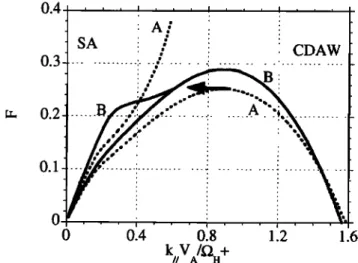
equatorward, untill they are reflected. Figure 7, curve A, shows the dispersion relation, off equator, in the maximum growth rate region. As the wave propagates towards higher latitudes
0.4. , , .
0.3
SA i ?
! CDAW
0.2 O.0
014
0.8
Figure 7. Dispersion relations for CDA and SA modes for two
different sets of parameters corresponding to two different positions along a field line, the abscissa is the parallel normalized k vector, k•. has been fixed along the field line (k•.=0.63). At point A: B=40 nT, V• =872 km/s; point B: B=55 nT, V• =1200 km/s. At
point B the CDA wave converts into SA wave. The SA mode is
later strongly damped, while its phase velocity increases (not
shown). See the text for discussion.
(dispersion relation labeled B), F is constant, F.+ increases, and K,/=k, Va/f2.+ decreases (V•/f•+ is assumed to be constant). The corresponding motion in the (F, k,) plane is indicated by an arrow. Curve B is defined by V• cos 0 -Va; at this point the SA and CDA modes merge (see the discussion in the previous
section).
Then a fraction of the energy will be convened into SA mode. Since the SA is also a guided mode it will keep on propagating toward higher latitudes; the corresponding dispersion relation is indicated by dotted line. During this propagation/mode conversion, F is fixed and k, decreases, hence •k, increases. Therefore we expect that the electrons will be accelerated/heated via Landau resonant interaction with the CDA/SA modes.
For the calculations described above, drifting electrons have been assumed to move only in one direction. If a symmetric beam is assumed, instead, and thus if there is no net current, wave
growth disappears, at least above Fi_i+. Even a slight asymmetry
either in the density or in the velocity (a field-aligned current), howewer, leads to recover a large growth rate. Such an asymmetry has been reported by Johnstone et al. [1994]. The magnetic signature seen on the V and D components in Figure 1 during early breakup (2017-2018 UT), also suggests the existence of a field-aligned current.
7. Conclusion
In an attempt to interpret ULF waves observed at breakup, we have carried out a parametric study of electromagnetic current- driven Alfvtn (CDA) waves. This mode results from the coupling between the FMS and SA modes via the relative parallel drift between electrons and ions (the parallel current). Thus the CDA mode has mixed properties; it is left-handed polarized as the SA mode and compressional, as the FMS. The instability is very robust; it is found to develop over a wide range of parameters. Present results are consistent with those of Gary et al. [ 1976], but we focus on nonparallel propagation and on values of T•/T•>>I, consistent with observations in the plasma sheet. The dispersion relation of CDA waves is different from that of the classical FMS/SA modes, in particular, for small K, it writes o•k,V d/2, therefore the parallel phase velocity is proportional to V• and not to Va. While SA and FMS modes are damped, even a small drift velocity destabilizes CDA waves. For oblique propagation the growth rate is about as large as for parallel propagation, and the frequency range is wider. The frequency range and ratios fiE/fiB critically depend on B; for the large B met in the equatorial NEPS, and for Vd/Vt•_>O. 1 and oblique propagation the frequency range
extends above F.+ and the •E/fB ratio is a few times V,•.
Therefore the observations of waves above F.+ does not imply that they are propagating in the FMS mode. The wide frequency
range (beyond F.+), and the large values of fiE/fiB obtained here
fit with the observations described by Perraut et al. [ 1993]. Given the strong relation between CDA waves and breakup, one is tempted to think that these waves play a role in accelerating particles and/or triggering substorms. Let us describe a possible scenario. As discussed in the previous subsection, the growth rate of CDA waves takes place at low latitudes, but off equator. Once generated CDA waves are well guided along the field lines. As they travel to higher latitude, CDA waves undergo a mode coupling with the SA waves, as illustrated in Figure 6. Thus the fraction of the energy, which is convened into SA mode, will propagate earthward (see Figure 7), essentially at the Alfvtn velocity. Since the Alfvtn velocity increases rapidly away from the magnetic equator, it will match the electron thermal velocity
PERRAUT ET AL.: CURRENT-DRIVEN ION INSTABILITY AT SUBSTORM ONSET 21,107
(co/k,,--V•--V,). Then CDA/SA waves that have a finite parallel electric field will be strongly damped via Landau damping. For to<to,.,, the first adiabatic invariant is conserved for electrons, thus electron diffusion will be along the magnetic field. We will study. in a forthcoming paper. the parallel diffusion of electrons and its effect on the reduction of the parallel current. Then a microscopic process: a current-driven instability is likely to have consequences on large-scale configuration of the tail via a modification of the current system.
Acknowledgements. We acknowletlge useful discussions with G.
Belmont. This work has been supported by CNES and by GDR PLASMAE
and PNST of CNRS.
Michel Blanc thanks S. Peter Gary anti another referee lbr their assistance in evaluating the paper.
References
B6singer, T., K. Aianko, J. 'Kangas, H. Opgenhoorth, and W. Baumjohann, Correlations between PiB type magnetic micropulsations, auroras and equivalent current structures during two isolated substorms, J. At,u•s.
Terr. Phys., 43,933,1981.
Drummond, W.E., and M.N. Rosenbluth, Anomalous diffusion arising l¾om microinstabilities in a plasma, Phys. Fluids, 5. 1507, 1962. Formisano, V., and C.F. Kennel. Small amplitude waves in high beta
plasmas, J. Plasma Phys., 3, 55, 1969.
Forslund, D.W.. J.M. Kindel, and M.A. Stroscio, Current driven
electromagnetic ion cyclotron instability, J. Plasma Phys., 21, 127,
1979.
Gary, S.P., and D.W. Forslund, Electromagnetic current instabilities, Phys.
Lett. A, 54(4), 347, 1975.
Gary, S.P., R.A. Gerwin, and D.W. Forslund, Electromagnetic current
instabilities, Phys. Fluids'. I% 579, 1976
Goertz, C.K., Electron acceleration via kinetic Alfv6n waves, in
Comparative Study of Magnetospheric •vstems, p. 357, Cepadues-
Editions, Toulouse, France, 1986.
Hasegawa, A., Plasma Instabilities and Nonlinear l:]Jbcts, Springer, New
York, 1975.
Hasegawa, A., and C. Uberoi, The Alfv6n wave, DOE Crit. Rev. Ser., DOE/TIC- 1197, Dep. of Energy, Washington, D.C., 1982.
Heacock, R.R., Two subtypes of type Pi micropulsations, J. Geophys. Res.,
72, 3905, 1967.
Holter, 0., C. Airman, A. Roux, S. Perraut, A. 'Pedersen, H. P6cseli, J.
Lybbekk, J. Trulsen, A. Korth, and G. Kremser, Characterization of low tYequency oscillations at substorm breakup, J. Geophys. Res.. ltXg
19,109, 1995.
Johnstone, A.D., N.J. Flowers, and R. Liu, Observations in the equatorial region of field-aligned electron and ion distributions in the energy range 100eV to 5 keV associated with substorm onsets, in Proceedings
of the 2 '• International Conj?rence on Substorms, edited by J.R. 'Kan,
J.D. Cravens, and S.-I. Akasofu, p. 321, Fairbanks, Alaska, March 1994, Geophys. Inst., Univ. of Alaska Fairbanks, Fairbanks, Alaska.
1994.
Kindel, J.M. and C.F. Kennel, Topside current instabilities, J. Geophys.
Res., 76 (13), 3055, 1971.
Le Contel O., R. Peilat, A. Roux, S. Perraut, A. Korth anti A. Pedersen,
Self-consistent convecti{•n during the growth phase, in Proceedings of the 4th International Conj?rence on Substorms-4, edited by S. Kokubun and Y. Kamide, p. 425, Lake Hamana, Japan, March 9-13. 1998, Terra Scient. Pub. Company. Tokyo, Kluwer Acad. Pub., 1998.
Le Contel, O., R. Pellat, and A. Roux, Self-consistent quasi-static parallel electric field associated with the substorm growth phase, J. Geophys. Res., in press, 2{XX).
Lui, A.T.. L.A. Frank, K.L. Ackerson, C.I. Meng, and S.-I. Akasol•, Systematic study of plasma flow during plasma sheet thinnings. J. Geophys. Res., 82, 4815, 1977.
Lui, A.T.Y., R.E. Lope7, B.J. Anderson, K. Takahashi, L.J. 'Zanetti, R.W. McEntire, T.A. P•temra, D.M. Klumpar, E.M. Greene. and R. Strangeway, Current disruptions in the near-Earth neutral sheet region, .!. Geophys. Res., 97, 1461, 1992.
Pertaut, S., A. Morane, A. Roux, A. Pealersen, R. Schmidt, A. Korth, G. Kremser, B. Aparicio and R. Pellinen, Characterization of small scale turbulence observed at substorm tinsets: Relationships with parallel accelerati•n of particles. Adv. 3]nace Res., 13(4), 217, 1993.
Pertaut, S.. A. Roux, O. Hoiter, A. Korth, G. Kremser and A. Pedersen,
Current sheet structure and relation to breakup, in Proceedings of the E3;A Cluster Workshop on Physical Measurements and Mission- Oriented Theor3.', Eur. 3•mce Agency 3•e. Publ., ESA SP-371, 239,
1995.
Pertaut S., O. Le Contel, A. Roux, R. Pellat, A. Pedersen and A. Korth, Evidence lbr a substorm trigger. in Proceedings qf the 4th International ConJbrence on Substorms-4, edited by S. Kokubun and Y. Kamide, p. 349, Lake Hamana, Japan, March 9-13, 1998, Terra Scient. Pub. Company, Tokyo, Kluwer Acad. PUb., 1998.
Pertaut S., A. Roux, F. Darrouzet, C. tie Viiledary, M. Mogilevsky, and F.
Lel•uvre, ULF waves measurements on h)ard the INTERBALL Auroral probe, Ann. Geophys., •6(9). i105, 1998.
Robert, P., R. Gentkin, S. Perraut, A. Roux and A. Pealersen. GEOS-2 identification of lastly moving current structures in the equatorial outer magnetosphere during substorms, J. Geopt•vs. Res., 89, 819, 1984. R6nnmark, K., WHAMP- Waves in Homogeneous Anisotropic
Multicomponent Plasmas. Kirtttta Geophys. Rep. 179, Kiruna Geophys.
Inst., Kiruna, 1982.
Roux, A., S. Perraut, A. Morane, and P. Robert. Role of the near Earth plasma sheet at substorms, in Magnetospheric Substorms, Geophys. Monogr. Set•, vol 64, p. 201, AGU, Washington. D.C., 1991a.
Roux, A., S. Pertaut, P. Robert, A. Morane, A. Korth, G. Kremser, B. Aparicio, D. Rodgers, and R. Pellinen, Plasma sheet instability related to the westward traveling surge, J. Geophys. Res., 96, 17,714, 1991 b. Shepherd, G.G., R. Bostrom, H. Derblom, C.-G., Falthammar, R. Gendrin,
K. Kaila, A. Korth, A. Pealersen, R. Peilinen, and G. Wrenn, Plasma
and field signatures of pole ward propagating auroral precipitation observed at the foot of the Geos 2 field line, J. Geophys. Rest, 95, 5845,
1990.
O. Le Contel, S. Perraut, and A. Roux, Centre d'6tude ties
Environnements Terrestre et Plan6taires, CNRS/UVSQ, 78140 V61izy, France.(syivaine.perraut @cetp.ipsl.fr)
A. Pedersen, Department of Physics, University of Oslo, 0316 Oslo,
Norway.
(Received October 29, 1999; revised March 17, 2000;