HAL Id: hal-02148733
https://hal.archives-ouvertes.fr/hal-02148733
Submitted on 5 Jun 2019
HAL is a multi-disciplinary open access
archive for the deposit and dissemination of
sci-entific research documents, whether they are
pub-lished or not. The documents may come from
teaching and research institutions in France or
abroad, or from public or private research centers.
L’archive ouverte pluridisciplinaire HAL, est
destinée au dépôt et à la diffusion de documents
scientifiques de niveau recherche, publiés ou non,
émanant des établissements d’enseignement et de
recherche français ou étrangers, des laboratoires
publics ou privés.
Copyright
Large Eddy Simulation of piloting effects on turbulent
swirling flames
A.X. Sengissen, Alexis Giauque, Gabriel Staffelbach, M. Porta, W. Krebs, P.
Kaufmann, Thierry Poinsot
To cite this version:
A.X. Sengissen, Alexis Giauque, Gabriel Staffelbach, M. Porta, W. Krebs, et al.. Large Eddy
Simula-tion of piloting effects on turbulent swirling flames. Proceedings of the CombusSimula-tion Institute, Elsevier,
2007, 31 (2), pp.1729-1736. �10.1016/j.proci.2006.07.010�. �hal-02148733�
Large Eddy Simulation of piloting effects
on turbulent swirling flames
Sengissen A. X.
?, Giauque A. S.
?, Staffelbach G. S.
?,
Porta M.
?, Krebs W.
†, Kaufmann P.
†and Poinsot T. J.
‡?CERFACS, 42 Avenue G. Coriolis, 31057 Toulouse cedex, France †Siemens PG, 45466 M¨uhlheim an der Ruhr, Germany
‡Institut de M´ecanique des Fluides de Toulouse, Avenue C. Soula, 31400 Toulouse, France
Abstract
Pilot flames, created by additional injectors of pure fuel, are often used in turbulent burners to enhance flame stabilisation and reduce combustion instabilities. The exact mechanisms through which these additional rich zones modify the flame anchoring location and the combustion dynamics are often difficult to identify, especially when they include unsteady hydrodynamic motion. This study presents Large Eddy Simulations (LES) of the reacting flow within a large-scale gas turbine burner for two different cases of piloting, where either 2 or 6 percent of the total methane used in the burner is injected through additional pilot flame lines. For each case, LES shows how the pilot fuel injection affects both flame stabilisation and flame stability. The 6 percent case leads to a stable flame and limited hydrodynamic perturbations in the initial flame zone. The 2 percent case is less stable, with a small-lift-off of the flame and a Precessing Vortex Core (PVC) in the cold stabilisation zone. This PVC traps some of the lean cold gases issuing from the pilot passage stream, changes the flame stabilisation point and induces instability.
Keywords: Combustion instabilities; Partially premixed; Swirled; Large Eddy Simulations
1. Introduction
Modern heavy duty gas turbines usually operate in lean premixed regimes to satisfy emissions regu-lations and can be very sensitive to combustion in-stabilities [1–3]. In most cases, flame stabilisation is provided by swirl injectors. A key zone of the cham-ber controlling instabilities is the burner outlet section
where swirl is very intense and must provide flame stabilisation. In these regions, the natural unstable modes of swirling flows (Precessing Vortex Cores or PVCs [4–8]) can interact with stabilisation and lift-off phenomena [9–12] to produce undesired oscillations. A method to encourage robust stabilisation is to use small pilot flames in these regions, usually by adding
lev-els and therefore a compromise between stabilisation and pollution levels must be sought. Furthermore, sta-bilisation is a difficult task because its basic mecha-nisms in a piloted swirled zone are not well under-stood. Proof of the importance of fuel injection are observed in active control examples in which a small modulation of flow rate in the fuel lines feeding the pilot flame can be sufficient to alter the stability of the combustor [13–15].
Large Eddy Simulation (LES) is becoming a standard tool to study the dynamics of turbulent flames [16–18]. The objective of this paper is to use LES (section 2) to compare two different cases of pi-loting in a gas turbine burner. Either 2 or 6 percent of the total methane used in the burner is injected ad-ditionally through pilot fuel lines. The burner is de-scribed in section 3. The 6% pilot fuel case leads to a robust and stabilized flame while the 2% case induces a small lift-off zone of the flame where a PVC can develop and lead to flame oscillations (section 4).
Because of the complexity of the burner, no de-tailed measurements are available. However, observa-tions in the full scale atmospheric test rig confirm LES predictions: the 2% leads to a more unstable flame than the 6% case.
2. Numerical approach used in Large Eddy Simulations
A fully compressible explicit code is used to solve the multi-species Navier-Stokes equations on hybrid grids [8, 19, 20]. Subgrid stresses are described by the classical Smagorinsky model [21]. A two-step chemical scheme is fitted for lean regimes on the GRI-Mech V3 reference [20]. The objective of the fit pro-cedure is that the two-step mechanism and the GRI mechanism must produce the same flame speeds and maximum temperatures for laminar premixed one-dimensional flames for equivalence ratios ranging be-tween φ = 0.4 and φ = 1.2.
The flame / turbulence interaction is modeled by the Dynamic Thickened Flame (DTF) model [22] which accounts for both mixing and combustion, and is crucial in partially premixed flames.
The explicit Lax-Wendroff numerical scheme uses second-order spatial accuracy and second-order time accuracy. The boundary condition treatment is based on a multi-species extension [19] of the NSCBC method [23], for which the acoustic impedance is con-trolled to minimise the unwanted reflections [24]. The adiabatic walls are handled using a logarithmic law-of-the-wall formulation which is known to perform well with the classical Smagorinsky model [25]. Typ-ical runs are performed on a grid composed of 1.4 million tetrahedra on parallel architectures. Multi-ple validations of this LES tool are available for non-reacting [26, 27] and non-reacting flows [8, 20, 28, 29].
3. Target configuration
The test geometry is an axisymmetric combustion chamber (Fig. 1-a), with a 3MW full scale burner inlet (Fig. 1-b). This burner is composed of two coaxial swirlers:
• The premix passage swirler contains 24 vanes.
Methane is injected through 10 small holes on each vane, ensuring efficient mixing and deliv-ering approximately 90% of the total mass flow rate. In the LES, this flow is assumed to be fully premixed.
• The pilot passage swirler (detailed in the upper
part of Fig. 1-b) delivers the remaining 10% of the flow rate (pure air). The central hub is con-nected to 8 vanes. Four additional tubes are in-serted between the 8 vanes to inject the methane used for piloting.
Pilot passage
Premix passage
Pilot fuel tubes (4) Pilot passage vanes (8)
Combustion chamber
Burner
inlet Exhaust
a)
b)
Fig. 1: a) Global view of the test geometry and b) zoom on the burner (pilot and premix passages) inner parts.
The computational domain includes all pilot pas-sage vanes as well as the pilot fuel tubes, but not the premix passage vanes. Appropriate profiles of veloc-ity and species are imposed to mimic the inlet exper-imental data [20] downstream of the premix passage vanes (Fig. 2).
The two operating points simulated in this study (2% and 6%) only differ by the fuel mass flow rates in the pilot fuel inlets:
• In the pilot passage stream, the fuel delivered by
pilot injection leads to a global equivalence ratio of φ = 0.36 (case 6%) and φ = 0.12 (case 2%), of which the latter is outside the flammability
limits. However, the very heterogeneous mix-ture may allow combustion to develop locally in rich pockets or in diffusion flamelets, depending on the mixing efficiency.
• In the premix passage stream, the imposed
pro-files in both cases correspond to a perfectly pre-mixed flow with an equivalence ratio of φ =
0.53.
4. Results and discussion
In swirling flows, the general mechanism leading to flame stabilisation is well known [8, 20]: a cen-tral core of hot gases is maintained along the burner axis by the strong recirculation zone induced by swirl. This section shows how this classical stabilisation mechanism is affected by the pilot flames. Figures 3 and 5 respectively present statistical profiles (time av-eraged and RMS values) of temperature and axial ve-locity in the central plane. The axial location of these profiles is shown on Fig. 2. Velocity, temperature and location along axis are normalised respectively by ref-erences Uref, Tref and the pilot passage radius R.
Premix passage inlet Pilot passage 0 1 2 Profiles in central plane Transverse plane x (Premixed) 3 4 5 6 7 R Pilot passage radius R Origin of axis Pilot tubes (Pure CH4) inlet (Air)
Fig. 2: Cross section of the test geometry and location of the planes used in Fig. 3, 5 and 8.
In the 6% pilot fuel case, the flame is clearly an-chored on the central hub of the pilot passage, and the temperature fluctuations remain small (Fig. 3-b): burnt gases are found along the axis from x = 0 to x = 2R. Flame lift-off appears in the 2% case (Fig. 3-a). The gases between x = 0 and x = 2R are cold. Hot pockets begin to appear after x = 2R but they are very intermittent, as demonstrated by the very large values of the RMS temperature (error bars on Fig. 3-a). A clearer understanding of the differ-ences between the two cases can be gained by plotting isosurfaces of temperature and stoichiometric equiv-alence ratio (Fig. 4). For the 6% case, the hot zone (T = 2/3 · Tref) is directly connected to the pilot passage hub (Fig. 4-b). For the 2% case, the flame is stabilised on a ’finger’ of burnt gases which is rotat-ing around the x-axis (Fig. 4-a), thereby inducrotat-ing the
a) 0 R 1 R 2 R 3 R 4 R 5 R 6 R 7 R 1.5 1.0 0.5 1.5 1.0 0.5 1.5 1.0 0.5 1.5 1.0 0.5 1.5 1.0 0.5 1.5 1.0 0.5 1.5 1.0 0.5 1.5 1.0 0.5 -6 -4 -2 0 2 4 6 Case 2% : Tmean : TRMS : error bars T = Tref : Cut at : T/Tref b) 0 R 1 R 2 R 3 R 4 R 5 R 6 R 7 R 1.5 1.0 0.5 1.5 1.0 0.5 1.5 1.0 0.5 1.5 1.0 0.5 1.5 1.0 0.5 1.5 1.0 0.5 1.5 1.0 0.5 1.5 1.0 0.5 -6 -4 -2 0 2 4 6 Case 6% : Tmean : TRMS : error bars T = Tref : Cut at : T/Tref
Fig. 3: Profiles of mean temperature (thick line), RMS of temperature (error bars) and T = Tref reference line (dashed line) for a) 2% case and b) 6% case.
large RMS fluctuations of temperature seen in Fig. 3-a.
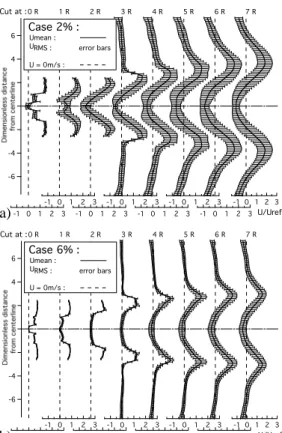
The axial velocity fields (Fig. 5) also present sig-nificant differences. For the 6% case, a very large zone with small velocities (mean as well as RMS) de-velops between x = 0 and x = 3R (Fig. 5-b). This zone contains the hot gases (Fig. 3-b) which provide stabilisation. The 2% case (Fig. 5-a) is characterised by a more intense recirculation (see for example cuts at x = 2R or x = 3R) and a much higher level of RMS velocities. This zone (between x = 0 and
x = 3R) contains cold gases (Fig. 3-a) which
experi-ence intense fluctuations. Even when the temperature increases (downstream of x = 3R), the velocity RMS values (Fig. 5-a) remain much higher for the 2% than for the 6% case, confirming that the 2% flame is not only lifted but also more hydrodynamically unstable. Instantaneous combustion regimes can be visu-alised by scatter plots of reaction rate versus local mixture fraction Z (Fig. 6). In both cases, most react-ing points are located very close to the global mixture fraction of the combustor Zmean, but in the 6% case, combustion also takes place at richer regimes, even slightly above stoichiometric (Zst), yielding higher maximum heat release. These points correspond to the roughly stoichiometric mixture issuing from the four pilot fuel jets after it has mixed with the premix
Fig. 4: Instantaneous isosurface of temperature (T = 2/3 ·
Tref, colored by axial velocity) and isosurface of
equiva-lence ratio (φ = 1, colored in blue) for a) 2% case and b) 6% case. color figure in print
passage air and passed through the vanes. By burning vigourously, these zones provide the robust stabilisa-tion observed in Fig 4-b. For the 2% case, almost no combustion takes place above the mean mixture fraction Zmean, indicating that the fuel injected in the pilot lines mixes too fast and cannot produce any significant diffusion flame zones which could provide stabilisation.
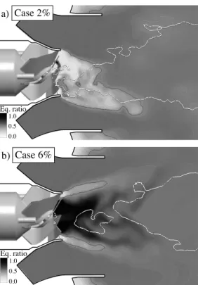
Typical instantaneous fields of equivalence ratio are displayed on Fig. 7. While the 6% case remains roughly axisymmetric and stoichiometric near the pi-lot passage hub, the 2% case in this zone has an asym-metric pattern below the flammability limit (φ < 0.4), which rotates around the x-axis.
The near stoichiometric zone of Fig. 7-b for the 6% case is the source of the robust stabilisation of this regime: this allows the flame to propagate back to the burner and anchor to the hub. On the other hand, for the 2% case (Fig. 7-a), mixing between the pilot fuel and the pilot passage air is too fast and leads to a mix-ture at the pilot passage mouth which is too lean for flame propagation. Figure 7 also shows a zone within which the flow is reversed. This central recirculation zone is delimited by the white isoline U = 0. Note
a) 0 R 1 R 2 R 3 R 4 R 5 R 6 R 7 R 3 2 1 0 -1 3 2 1 0 -1 3 2 1 0 -1 3 2 1 0 -1 3 2 1 0 -1 3 2 1 0 -1 3 2 1 0 -1 3 2 1 0 -1 -6 -4 -2 0 2 4 6 Case 2% : Umean : URMS : error bars U = 0m/s : Cut at : U/Uref b) 0 R 1 R 2 R 3 R 4 R 5 R 6 R 7 R 3 2 1 0 -1 3 2 1 0 -1 3 2 1 0 -1 3 2 1 0 -1 3 2 1 0 -1 3 2 1 0 -1 3 2 1 0 -1 3 2 1 0 -1 -6 -4 -2 0 2 4 6 Case 6% : Umean : URMS : error bars U = 0m/s :
Cut at :
U/Uref
Fig. 5: Profiles of mean velocity (thick line), RMS of veloc-ity (error bars) and U = 0 reference line (dashed line) for a) 2% case and b) 6% case.
Z
stZ
meanCase 2%
Case 6%
Mixture fraction Z
Dimensionless heat release
a)
b)
Fig. 6: Scatter plot of instantaneous heat release versus mix-ture fraction for a) 2% case and b) 6% case.
that the 6% case exhibits a smaller zone of reversed flow (as expected from the mean velocity profiles of Fig. 5) than the 2% case. Obviously, having reversed flow is not a sufficient criterion for stabilisation: hav-ing robust burnhav-ing pilot flames is more important (as for the 6% case). For the 2% case, the absence of combustion in this zone leads to a lean cold region in
1.0 0.5 0.0 Eq. ratio Case 2% a) 1.0 0.5 0.0 Eq. ratio Case 6% b)
Fig. 7: Instantaneous field of equivalence ratio on central plane for a) 2% case and b) 6% case. Flammability zone (φ = 0.4): black line. Recirculation zone (U = 0): white line.
which even reversed flow can not anchor the flame. The existence of such a lean and cold zone leads to the formation of a PVC [4–8]. This PVC only occurs in the 2% case and precesses at 408Hz. The drastic change of velocity field near the pilot passage mouth for this case presented on Fig. 5 is one of the factors which most probably facilitate its development.
A specific feature of the 2% case is the correlation between the lean jet of methane and cold air issuing from the pilot passage and the low pressure zone due to the PVC structure. Figure 8 displays fields of pres-sure, temperature and local equivalence ratio (recon-structed through the mixture fraction) for both pilot fuel cases in a transverse plane at x = 3R.
The low pressure regions are a good indicator of the PVC presence (Fig. 8-a), and are well correlated with the cold (Fig. 8-b) and lean (Fig. 8-c) regions for the 2% case. The PVC appears to capture some of the lean cold gases produced by the pilot passage and prevents their mixing with the surrounding prod-ucts. This observation is consistent with detailed mix-ing studies of jet / vortex interaction which show that mixing can be strongly decreased within vortex struc-tures [30].
The flame then features a cold non-reacting ”finger-like” rotating structure protruding within the stabilisation zone (illustrated by Fig. 4-a and sketched on Fig. 9). This is clearly not favorable either for
Case 2% Case 6% 0.98 0.94 0.90 Pressure (bar) a) 0.98 0.94 0.90 Pressure (bar) a’) 1.2 0.8 0.4 T / Tref b) b’) 1.2 0.8 0.4 T / Tref 0.55 0.47 0.40 Equiv. ratio c) 0.55 0.47 0.40 Equiv. ratio c’)
Fig. 8: Instantaneous fields of a) pressure, b) dimensionless temperature and c) equivalence ratio on transverse plane (see Fig. 2) for 2% case (left) and 6% case (right).
Lean cold mixture trapped within PVC
Flame front Stabilising
rotating finger
Transverse plane
Fig. 9: Sketch of the finger-like rotating structure for the 2% case and location of the transverse plane (see Fig. 8).
flame stabilisation nor for thermoacoustic stability: RMS pressure levels for the 2% case can be as high as 6000 Pa (170 dB) on the axis and the noise is ra-diated to 2000 Pa (160 dB) at the wall while they do not exceed 500 Pa for the 6% case. For the 6% case, the situation is very different: a PVC is not observed (Fig. 8-a’), less cold gas reaches the plane at x = 3R (Fig. 8-b’) and lean gases are not found around the
axis (Fig. 8-c’).
The mechanism leading to the PVC formation in the 2% case is purely due to hydrodynamic and com-bustion effects but not to acoustic coupling. A ba-sic proof of the absence of acoustic coupling can be assessed by comparing the acoustic eigenfrequencies of the combustion chamber with the precessing fre-quency of the PVC (408 Hz). The fundamental trans-verse eigenmode is 575 Hz, and the non reflecting in-let/outlet treatment [24] is built to damp all the longi-tudinal modes.
5. Conclusions
This study presents Large Eddy Simulations (LES) of piloting effects in a full-scale gas turbine burner. By computing explicitely all details of the pilot pas-sage zone where pure pilot methane is injected up-stream of the vanes, LES provides new insights on the key mechanisms that control flame stability. When enough methane is injected in the pilot zone (in the 6% case), a roughly stoichiometric zone is formed at the burner mouth, allowing flame propagation within this zone and preventing the formation of a Precess-ing Vortex Core (PVC). On the other hand, when the flow rate of pilot fuel is too small (in the 2% case), the mixture issuing from the pilot passage is too lean, preventing flame stabilisation and leading to the for-mation of a PVC containing lean cold gases which di-minishes the effect of piloting even more. Obviously, between the 2% and 6% piloting cases, a bifurcation takes place in the basic flow structure. The significant effects of this bifurcation captured by LES coincide with observations on stability limits in the full scale test rig.
Acknowledgments
This work was carried out with the support of Siemens PG in the framework of EC project DESIRE. Most numerical simulations have been conducted on the computers of CINES, the French national com-puting center, on a SGI origin 3800.
References
[1] W. Polifke, A. Fischer, T. Sattelmayer, J. Eng.
for Gas Turb. and Power 125 (2003) 20–27.
[2] V. Sankaran, S. Menon, J. Turb. 3 (2002) 011. [3] D. Smith, E. Zukoski, in: 21st Joint Propulsion
Conference, Monterey, 1985, pp. 85–1248.
[4] P. Billant, J.-M. Chomaz, P. Huerre, J. Fluid
Mech. 376 (1998) 183–219.
[5] A. Gupta, D. Lilley, N. Syred, Swirl flows, Aba-cus Press, 1984.
[6] M. Hall, Ann. Rev. Fluid Mech. 4 (1972) 195– 217.
[7] O. Lucca-Negro, T. O’Doherty, Prog. Energy
Comb. Sci. 27 (2001) 431–481.
[8] S. Roux, G. Lartigue, T. Poinsot, U. Meier, C. B´erat, Combust. Flame 154 (2005) 40–54.
[9] Y. Mizobuchi, J. Shinjo, S. Ogawa, T. Takeno,
Proc. Combust. Inst. 29 (2004) 2009–2015.
[10] L. Mu˜niz, M. Mungal, Combust. Flame 111 (1-2) (1997) 16–31.
[11] H. Pitsch, H. Steiner, Phys. Fluids 12 (2000) 2541–2554.
[12] L. Vervisch, R. Hauguel, P. Domingo, M. Rul-laud, J. Turb. 5 (2004) 004.
[13] C. Hantschk, J. Hermann, D. Vortmeyer, Proc.
Combust. Inst. 26 (1996) 2835–2841.
[14] K. McManus, T. Poinsot, S. Candel, Prog.
En-ergy Comb. Sci. 19 (1993) 1–29.
[15] T. Poinsot, D. Veynante, B. Yip, A. Trouv´e, J.-M. Samaniego, S. Candel, J. Phys. III July (1992) 1331–1357.
[16] H. Pitsch, Ann. Rev. Fluid Mech. 38 (2006) 453–482.
[17] N. Peters, Turbulent combustion, Cambridge University Press, 2000.
[18] T. Poinsot, D. Veynante, Theoretical and
numer-ical combustion, R.T. Edwards, 2001.
[19] V. Moureau, G. Lartigue, Y. Sommerer, C.
An-gelberger, O. Colin, T. Poinsot, J. Comput.
Phys. 202 (2005) 710–736.
[20] L. Selle, G. Lartigue, T. Poinsot, R. Koch, K.-U. Schildmacher, W. Krebs, B. Prade, P. Kauf-mann, D. Veynante, Combust. Flame 137 (4) (2004) 489–505.
[21] J. Smagorinsky, Mon. Weather Review 91 (1963) 99–164.
[22] J.-P. L´egier, T. Poinsot, D. Veynante, in:
Sum-mer Program 2000, Center for Turbulence
Re-search, Stanford, USA, 2000, pp. 157–168. [23] T. Poinsot, S. Lele, J. Comput. Phys. 101 (1)
(1992) 104–129.
[24] L. Selle, F. Nicoud, T. Poinsot, AIAA Journal 42 (5) (2004) 958–964.
[25] W. Cabot, P. Moin, Flow Turb. and Combustion 63 (2000) 269–291.
[26] C. Pri`ere, L. Gicquel, A. Kaufmann, W. Krebs, T. Poinsot, J. Turb. 5 (2004) 1–30.
[27] J. Schl¨uter, Int. J. Numer. Meth. Fluids 18 (3) (2004) 235–246.
[28] C. Martin, L. Benoit, F. Nicoud, T. Poinsot,
AIAA Journal in press.
[29] Y. Sommerer, D. Galley, T. Poinsot, S. Ducruix, F. Lacas, D. Veynante, J. Turb. 5 (2004) 037. [30] R. Paoli, F. Laporte, B. Cuenot, T. Poinsot,