HAL Id: hal-02623881
https://hal.archives-ouvertes.fr/hal-02623881
Submitted on 26 May 2020
HAL is a multi-disciplinary open access
archive for the deposit and dissemination of
sci-entific research documents, whether they are
pub-lished or not. The documents may come from
teaching and research institutions in France or
abroad, or from public or private research centers.
L’archive ouverte pluridisciplinaire HAL, est
destinée au dépôt et à la diffusion de documents
scientifiques de niveau recherche, publiés ou non,
émanant des établissements d’enseignement et de
recherche français ou étrangers, des laboratoires
publics ou privés.
ultrafiltration membranes supported on natural zeolite
for removal of heavy metals from wastewater
Wala Aloulou, Hajer Aloulou, Mouna Khemakhem, Joelle Duplay, Michael
Daramola, Raja Ben Amar
To cite this version:
Wala Aloulou, Hajer Aloulou, Mouna Khemakhem, Joelle Duplay, Michael Daramola, et al.. Synthesis
and characterization of clay-based ultrafiltration membranes supported on natural zeolite for removal
of heavy metals from wastewater. Environmental Technology and Innovation, Elsevier, 2020, 18,
�10.1016/j.eti.2020.100794�. �hal-02623881�
Synthesis and characterization of clay-based ultrafiltration membranes
supported on natural zeolite for removal of heavy metals from wastewater
Wala Aloulou
a, Hajer Aloulou
a, Mouna Khemakhem
a, Joelle Duplay
b,
Michael O. Daramola
c, Raja Ben Amar
a,∗a Laboratoire Sciences des Matériaux et Environnement, Université de Sfax, Faculté des Sciences de Sfax, BP 1141, 3018 Sfax, Tu nisia b EOST-LHYGES, UMR 7517 CNRS, Université de Strasbourg, France
c School of Chemical and Metallurgical Engineering, University of the Witwatersrand, Wits 2050, Johannesburg, South Africa
Keywords: Nanocomposite
smectite Zeolite support Layer-by-Layer (LBL) Ceramic UF membrane Heavy metals
Industrial effluent treatment
a b s t r a c t
High cost of high-purity materials is one of the major factors that limit the application of ceramic membranes. Consequently, focus has been shifted to using natural low cost materials such as clay, apatite as alternatives to well-known other metallic oxides like alumina, silica, zirconia and titania. As a contribution to this area, development and evaluation of new but low cost ultrafiltration (UF) ceramic membranes made from nanoparticles of smectite (previously prepared by sol-gel method) are presented in this article. The UF composite membranes were obtained via the Layer-by-Layer technique, and deposited on tubular microporous supports obtained from natural zeolite via the extrusion process. Four different membranes namely; Sm/Z4 (with four layers), Sm/Z5 (with five layers), Sm/Z6 (with six layers) and Sm/Z7 (with seven layers) were prepared. Morphological and textural properties of the membranes (sintered at 900
◦C for 3 h) were determined by BET and SEM. The measured pore diameters (dp) of the membranes were in
the following ranges: 3 nm–13 nm for Sm/Z4; 2 nm–11 nm for Sm/Z5; 3 nm– 5 nm for Sm/Z6; and 14 nm–21 nm for Sm/Z7. Heavy metal removal efficiency of these membranes was evaluated using a home-made cross-flow UF pilot plant operated at a temperature of 25 ◦C with trans-membrane pressure (TMP) ranging from 3 bar to 7 bar. Pure water permeability of these membranes varied from 1218 L/h m2 bar for
the ordinary zeolite support (before layer deposition) to 73 L/h m2 bar; 65 L/h m2 bar; 59 L/h m2 bar and
95 L/h m2 bar for Sm/Z4, Sm/Z5, Sm/Z6 and Sm/Z7, respectively. During the treatment of wastewater
(containing heavy metals) obtained from electroplating industry using these membranes, a significant decrease in turbidity (< 1 NTU) was observed and the chemical oxygen demand (COD) removal for Sm/Z6 was > 96%. In addition, the Sm/Z6 membrane displayed heavy metal removal efficiency of >89% for chromium. The overall data suggest that the developed and tested nanocomposite membranes have potential for remediation of industrial effluents contaminated by heavy metals.
∗ Corresponding author.
E-mail addresses: walaaloulou6@gmail.com(W. Aloulou),hajer.aloulou89@yahoo.fr(H. Aloulou),khemakhem.mouna@yahoo.com (M. Khemakhem),jduplay@unistra.fr(J. Duplay),benamar.raja@yahoo.com(R. Ben Amar).
≥
1. Introduction
Industrial activities such as mining activities, electroplating etc. are generating multiple metallic pollutants considered as one of the greatest concerns because of their toxicity and their accumulation in the environment (air, water and soil). In particular, heavy metals like cadmium (Cd), chromium (Cr), cobalt (Co), mercury (Hg) and lead (Pb), even in trace amounts, cause harmful effects like respiratory irritation and hepatic cell destruction (Banni et al.,2005;Kessabi et al., 2008;Barhoumi et al.,2009). In aquatic environment, they can affect marine organisms (fish, mollusks, tuna, etc.) living near the industrialized coastline (Hamza Chaffai et al.,1995;Kessabi et al.,2010;Zhu et al.,2015) and fishing harbor.
In the environment, heavy metals come from wastewater of various industries such as surface treatment and electroplating industries, (Panayotova et al.,2007). Usually, Cr (VI) is the predominant form of chromium in most water streams and surface waters (Hashim et al.,2011).
Due to the higher solubility and mobility in eco systems, chromium (VI) ions are considered the most toxic compared to other forms of chromium salts (Muthukrishnan and Guha,2008). Moreover, Cr (VI) is included in the list of the US environmental protection agency for prioritizing control of its application. According to the World Health Organization standards, the acceptable level of chromium in drinking water is 0.05 mg/L for Cr (VI) and 0.1 mg/L for total Cr (Mahmoud et al.,2016).
Development of economical and effective technology for elimination of heavy metals from drinking water and wastewater has usually been an enormous interest for researchers (Bhattacharya et al.,2014). Membrane technology and adsorption are among the most investigated techniques for the wastewater treatment (Kumar et al.,2007;Mondal et al.,2013;Daramola et al.,2015;Chen et al.,2017;Quist-Jensen et al.,2017;Mathaba and Daramola,2019;Daramola
et al.,2019;Bareera et al.,2020). In the last decade, the separation potential of nanofiltration (NF) and reverse osmosis (RO) membranes has been considered as promising processes for the removal of metals and salts of different valences (Quist-Jensen et al.,2017). However, NF and RO require more energy than ultrafiltration (UF) due to the application of high pressure for the operation. In addition, polymeric membranes are plagued with lower thermal stability and poor mechanical strength when compared to ceramic membranes (Lastra et al.,2004;Daramola et al.,2012).
Ceramic composite membranes have better antifouling property with enhanced mechanical and chemical stability than polymeric composite membranes. Preparation of composite ceramic membranes needs the use of powder having a pore size range commonly below the interval of membrane pore size (Rastgar et al.,2017). Nevertheless, the membrane pore size can be reduced via surface modification of the membrane by cross-link age using various polymers (Rameeetse et al., 2019;Mathaba and Daramola,2019); embedding nanoparticles within the polymer matrix (Daramola et al.,2015) or coating with nanoparticles as the active layer (Kasemset et al.,2017;Wan et al.,2017). In this context, a large number of research works has been devoted to the development of new types of inorganic membranes from low cost materials (Aloulou et al.,2018) and (Tahri et al.,2013). Majority of these studies concentrated on the application of (UF) membranes in pollution preventionSaffaj et al.(2010). Mc Bain and his co-authors were the first to notice the retention of ionic species under certain conditions by UF membrane (McBain and Kistler,1931).Saffaj et al.(2005) coated a cordierite support with TiO2–ZnAl2O4 to reduce the average pore size of the support to 4 nm and then applied the modified material as an
UF membrane to remove salts and dyes from wastewater. Recently,Choudhury et al.(2018) fabricated a novel CuO/HEC (hydroxyethyl cellulose) composite ceramic UF membrane with average pore size of 3 nm and applied it to remove Cr
(VI) and Pb (II) from contaminated water. The authors observed that the role of the mixed valence of the copper (Cu), due to electron transfer, was important in the separation of Pb and Cr, because of their simultaneous oxidation and reduction properties.
A total removal of chromium ions from potable water with a concentration less than 25 ppm was achieved at pH 7 in presence of a new polyacrylonitrile (PAN) based (UF) membrane (Muthumareeswaran et al.,2016). Steenkamp et al.
reported also the use of biopolymer chitosan based composite ceramic membrane including alumina for the removal of heavy metal from aqueous solution (Steenkamp et al.,2002).Sanyal et al.(2015) proposed modification of commercial (NF) membranes by the method of Layer-By-Layer (L.b.L) assembly to enhance ion rejection from wastewater. According to the authors, the performance of the membrane was comparable to that of commercial RO membranes, but with much higher permeability. Furthermore, the authors reported that the mechanism of ion rejection was based on size exclusion rather than charge-based separation.Breida et al.(2017) reported that the rejection of nitrate through an UF γ -Al2O3
membrane with a nominal pore size of 5 nm strongly depends upon the total mineralization and the presence of divalent anions in solution.Sachdeva and Kumar(2008), showed that chromate ion rejection via charged ceramic UF membrane is strongly dependent on Donnan exclusion principle at basic pH conditions, while size exclusion principle for UF does not play a major role on ion rejection. On the other hand, it was found that removal of more than 90% of chromate ions at alkaline condition could be achieved using modified UF charged carbon membranes with a macroporous clay support (Pugazhenthi et al.,2005).
Against this background, this study is a follow up on one of the previous studies related to the preparation of composite UF tubular ceramic membranes from zeolite and the use of the zeolite membranes as supports for smectite nanoparticles (Aloulou et al.,2018). However, in this present study Layer-by–Layer (LBL) method was used to prepare a UF composite ceramic membrane from smectite (Sm) nanoparticles and zeolite (Z). As far as could be ascertained, no reports in open literature have discussed the use of L.B.L to prepare zeolite based ceramic membrane coated with nanoparticles. The fabricated membranes were characterized using a wide range of physico-chemical analysis methods and applied to the treatment of real wastewater from electroplating industry.
Fig. 1. Preparation of TiO2-smectite nanostructured materials based on colloid rout method.
Fig. 2. Temperature–time schedule of membrane sintering.
2. Materials and methods
2.1. Materials
The nanoparticle Smectite (Sm) powder was prepared by using a colloidal route as described elsewhere (Aloulou et al., 2018). Thus, titanium (IV) isopropoxide was incorporated within the organophilic layer and developed on the surface of the alumino-silicate-grains (Fig.1). The nanoparticle Smectite (Sm) powder has several properties: a homogeneous structure of the particles; the mean pore size in the range of 8–12 nm; and a uniform distribution of the TiO2 nanoparticles.
Tubular micro-porous supports from natural zeolite have previously been made in our laboratory by extrusion process. These supports were sintered at 900 ◦C exhibiting high mechanical resistance, porosity and chemical stability (pore diameter: 0.55 µm and porosity: 43.7%) (Aloulou et al.,2017).
Table 1
Composition of the slurry solutions.
Component Conditions Proportion (%)
Water Distilled 68
Polyvinyl alcohol (aqueous solution) 12% aqueous solution 30
Nanoparticules (sol–gel ) Fine powder 2
Table 2
Deposition layers duration during the preparation of the three UF Sm/Z membranes.
Number of layer Sm/Z4 Sm/Z5 Sm/Z6 Sm/Z7
1st layer The slip emptied The slip emptied The slip emptied The slip emptied
immediately immediately immediately immediately
2nd layers 1 min 1 min 1 min 1 min
3th layer 3 min 3 min 3 min 3 min
4th layers 3 min 3 min 3 min 3 min
5th layers – 3 min 3 min 3 min
6th layers – – 3 min 3 min
Sintering at 900 ◦C
1st layer The slip emptied
– immediately
2nd layers 1 min
3th layer 3 min
Sintering at 900 ◦C
2.2. Membrane fabrication
The Layer-By-Layer approach was applied to form the nanoparticles Sm/Ti UF membrane using previously elaborated macroporous supports. For the fabrication of the ultra-filtration layer, a deflocculated slip was prepared by mixing nanocomposite smectite (Sm), polyvinyl alcohol (PVA) (Rhodoviol 25/140 (Prolabo)) as a binder, and water (Table1) (Aloulou et al.,2018). The dispersion was stirred for 5 min and then sonicated in ultrasonic bath for 10 min (using a 500 W tip Sonica Q Sonica Newton ct). The same slip composition was optimized to prepare the different UF membranes Sm/Z4 (membrane with 4 coated layers), Sm/Z5 (membrane with 5 coated layers), Sm/Z6 (membrane with 6 coated layers), and Sm/Z7 (membrane with 7 coated layers).
Deposition of the slip on the zeolite tubular support was ensured using the Layer-By-Layer approach (Aloulou et al., 2018). The closed-end tube used was 150 mm in length and had an inner diameter of 7 mm. It is worthy to note that the coating process using the L.B.L method is similar to that performed by the slip casting method, except the coating action is repeated at different deposition times. The L.B.L process consists essentially of four steps:
(i) Putting in suspension the mineral powder in water.
(ii) Adding a binder (12 wt% aqueous solution of polyvinyl alcohol ‘PVA’ and homogenization using a magnetic stirrer). (iii)Coating the inner
surface of the support at room temperature for a few minutes. For tubular membranes, the support was closed at one end and filled with the solution. (iv)Drying is
carried out at room temperature for 24 h.
Table2shows the different deposition times for the fabrication of the four UF membranes: Sm/Z4, Sm/Z5, Sm/Z6 and Sm/Z7. For each membrane, a sintering step was applied after the last layer deposition. In the case of Sm/Z7, two sintering steps were applied; the first after the sixth layer and the second after the last layer deposition. The purpose of two sintering steps was to further reduce the mean pore size of the membrane by enhancing the compactness of the particles. The drying of the different UF membranes Sm/Z4, Sm/Z5, Sm/Z6 and Sm/Z7was carried out at room temperature for 24 h.
After drying at room temperature for 24 h, the UF membranes Sm/Z4, Sm/Z5 and Sm/Z6 were sintered at 900 ◦C for
3 h according to a given temperature–time schedule (Fig.2) (Aloulou et al.,2018). For Sm/Z7, similar temperature–time schedule of membrane
sintering and final sintering temperature of 900 ◦C were applied successively. The hot plate was kept at 250 ◦C for 2 h in order to completely eliminate the PVA from the slip. Then a temperature increase until 900 ◦C was applied at relatively slow rate (2 ◦C/min) in order to avoid the formation of cracks on the layer. Finally, the membranes were allowed to cool down naturally under natural convection.
2.3. Membrane characterization
The morphology of the membranes was obtained using a scanning electron microscopy (SEM, Zeiss MERLIN scanning electron microscopy), and their textural property (especially the total surface area) was obtained by probing the solid surface with Nitrogen as the gaseous adsorbate and using the BET (Brunauer– Emmet-Teller) method. The pore size
distribution of the top layer was obtained from nitrogen adsorption/ desorption isotherm using Analyseur Micrometrics, ASAP 2020 instruments. In order to determine the interaction with the membrane, the point of zero charge (pHpzc ) was quantified using a zetameter (Zeta Sizer Nano
series- 25).
2.4. Separation performance evaluation of the membranes
The membranes were evaluated for the removal of heavy metals from real wastewater using a home-made cross flow UF filtration set-up as described elsewhere (Khemakhem et al.,2009) at a temperature of 25 ◦C and a transmembrane pressure (TMP) between 3 and 7 bar. The transmembrane pressure was controlled by an adjustable valve at the retentate side. The experiments were performed by recovering the permeate while the retentate was recycled back to the feed tank. The permeate was analyzed for heavy metals, chemical oxygen demand (COD), dissolved particles, conductivity etc. after a two-hour experimental duration. Prior to the tests, the UF membrane was immersed in pure distilled water for at least 24 h to equilibrate them. Water flux through the membrane was then measured as a function of time at different transmembrane pressure. The duration of each test ranged from 1 to 3 h.
The physico-chemical parameters of the real effluent and of the permeate were determined according to the standard methods set by the American Public Health Association (Standard Methods for the Examination of Water and Wastewater 1998). Conductivity and pH determinations were done by means of a conductivity meter (ISTEK EC-400L) and pH-meter (STEK pH-220L) respectively. Turbidity was measured using turbidity meter (Hach RATIO 2100A) in accordance with standard method 2130B; a calibration standard is considered necessary. COD was estimated by open-reflux method, according to a method derived from the Standard AFNOR T90-101. The sample was refluxed in an acidic medium with a definite excess of potassium dichromate and the rest of dichromate was titrated with ferrous ammonium sulphate. The COD was obtained using a Fisher Bioblock Scientific reactor COD 10119 type COD meter. The equilibrium concentration of (Cr (VI) and Co) were determined by using an atomic adsorption spectrophotometer (AAS) (Perkin Elmer A Analyst 200).
3. Results and discussion
3.1. Pore size using BET characterization
Fig.3(a–d) shows the pore size distribution of the top layers of the three Sm/Z UF membranes sintered at 900 ◦C/ 3 h. The measured mean pore diameters (dp) for the different UF membranes ranged as follows: 3 nm < dp Sm/Z4< 13 nm, 2 nm< dp Sm/Z5< 11 nm, 3 nm< dp Sm/Z6< 5 nm and 13 nm< dp Sm/Z7< 19 nm. The textural property (e.g. pore size) obtained from the BET analysis shows an increase in pore size because of the evolution of the densification in inner and outer parts resulting in the increase of the membrane porosity (Mohd Ridhwan et al.,2017). In addition, it was observed that the pore size distribution seems rather homogeneous for Sm/Z6 UF membrane when compared to other membranes.
3.2. Scanning Electron Microscopy (SEM)
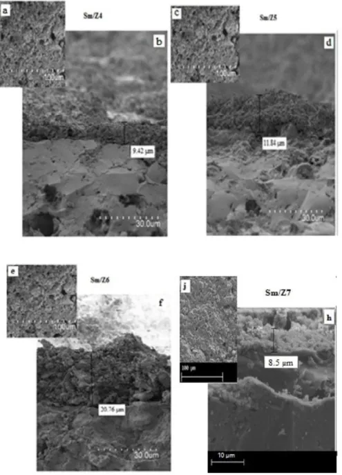
Fig.4(a, c, e and j) shows the surface morphology of the membranes whileFig.4(b, d ,f and h) shows the surface and cross-section morphology of the membranes as obtained from SEM for different zeolite UF membranes sintered at 900 ◦C/ 3 h. It should be noticed that the selected temperature range for thermal treatment was based on the sintering temperature of the support which was found to be in the range 900 ◦C (Aloulou et al.,2018). It is clearly observed that all samples have a homogenous and smooth surface structure without any macro defects (cracks).
From cross-section micrographs (Fig.4(b, d, f and h)), formation of open pores with no cracks could be observed with excellent adhesion between the UF layer and the support.
For the four membranes, it is noticed that the slip used allows an easy and sufficient flow of the suspension inside the membrane support without deep infiltration. The formation of the four UF membranes took place after a deposition time of 8; 11; 13 and 17 min, respectively, for Sm/Z4, Sm/Z5, Sm/Z6 and Sm/Z7. Furthermore, the membrane thickness for Sm/Z4, Sm/Z5, Sm/Z6 and Sm/Z7 was 9.42 µm, 11.84 µm, 20.76 µm and 8.5
µm, respectively, indicating the effectiveness of the application of L.B.L process for membrane coating. It can be seen that the membrane Sm/Z7 became completely dense and compacted accompanied with the presence of macro voids all over the structure with two successive sintering steeps (Fig.5) (Mohd Ridhwan et al.,2017). Overall, the membranes are typical of a UF since ultrafiltration active layers were directly deposited on the support without the need of an intermediate microfiltration layer (MF) as it is usually considered (Masmoudi et al.,2006;Khemakhem et al.,2007). This procedure limits the resistance against the mass transfer and consequently enhances the filtration performance of the membranes.
3.3. Pure water permeation
The permeability of the different UF membranes, sintered at 900 ◦C/ 3 h, was determined using distilled water. The membrane permeability was determined using the variation of the distilled water flux Jw (L/h m2 ) with TMP (bar) according to the Darcy’s law Eq.(1):
Fig. 3. Pore size distribution of the top layer of Sm/Z4, Sm/Z5, Sm/Z6 and Sm/Z7 UF membranes sintered at 900 ◦C.
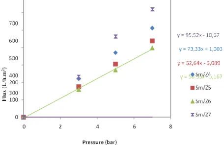
The water permeability Lp (L/h m2 bar1 ) was obtained from the slope of the water flux (Jw ) versus applied pressure across the membrane
(∆P (bar)) (Fig.6).
The water permeability varied from 1218 L/h m2 bar for the zeolite support before layer deposition to 73 L/h m2 bar; 65 L/h m2 bar; 59 L/h m2 bar
and 95 L/h m2 bar after coating, respectively, for the Sm/Z4, Sm/Z5, Sm/Z6 and Sm/Z7.
Table3shows the characteristics of different fabricated UF membranes. Based on UF membranes characteristics in terms of BET, SEM and membrane permeability, it can be concluded that when only one layer is considered, Sm/Z6 membrane displayed better texture (homogenous, smooth, and defect-free surface) when compared to others. It seems that Sm/Z6 UF membrane was the most suitable for the removal of heavy metals from waste water. The membrane Sm/Z7 is eliminated because it has highest pore sizes and permeability.
3.4. Membrane resistance
The membrane resistance (Rm) was then obtained according to the Darcy’s law, taking into account the series resistance model:
TMP
Jw =
µ.Rm
Fig. 4. Scanning electron micrographs of different membranes sintered at 900 ◦C: surface (a, c, e and j) and cross-section (b, d,f and h). Table 3
Characteristics of different fabricated UF membranes. Membrane Thickness
(µm)
Average pores size (nm) Permeability (L/h m2 bar)
Sm/Z4 9.42 3 nm < dp Sm/Z4 < 13 nm 73
Sm/Z5 11.84 2 nm < dp Sm/Z5 < 11 nm 65
Sm/Z6 20.76 3 nm < dp Sm/Z6 < 5 nm 59
Sm/Z7 8.50 14 nm < dp Sm/Z7 < 21 nm 95
=
Fig. 5. Scanning electron micrographs of the membrane Sm/Z7 sintered at 900 ◦C: surface (a) and cross-section (b).
The quantification of the elaborated membranes (Sm/Z3 (Aloulou et al.,2018), Sm/Z4, Sm/Z5 and Sm/Z6) resistances (Rm) is shown inFig.7(a).
As it can be observed, the Rm grows linearly with the number of the deposited layers between the third and the fifth one and then becomes
independent of the number of deposited layers.
Based on this result, a number of six layers can be considered acceptable to obtain an UF membrane. Moreover, UF Sm/Z6 membrane exhibits no cracks or pinholes as could be observed fromFig.4e.
Moreover taking into account the Hagen–Poiseuille law applied in porous media, the permeation flux can be written under the following form:
With: J Nπ R4∆P 8µe (3) J : Membrane permeability (L/h m2 ) R: pore radius (nm)
µ: Viscosity of the solution (Pa.s)
∆P: transmembrane pressure (Pascal)
=
=
=
Fig. 6. Flux (L/h m2 ) versus pressure (bar) for different membranes, and linear regression lines and equations used for the determination of the UF membranes permeability.
N : pore number/m2
With N ε
π R2τ
ε: pore volume/ total volume of the membrane
τ : membrane tortuosity Then, Eq.(3)can be written as:
J εR2∆P
8τe
The Eq.(5)can be written as:
J K∆P µe
(4)
(5)
(6)
Considering Eq.(6), the permeability of the membrane is proportional to the square of the radius of to the pores and the active layer.Fig.7(b) shows the evolution of the membrane permeability with r 2 /∆x taking into account the number of the deposited layer for each membrane.
A linear variation of the Sm /Z4 membrane at Sm /Z6 is obtained whereas the variation varies for the Sm/Z3 membrane, which seems that the texture of the membrane in terms of surface density of the pores and tortuosity is almost the same for the three membranes Sm /Z4, Sm/Z5 and Sm/Z6, however this is not the case for Sm/Z3 (Aloulou et al.,2018).
4. Application to treatment of industrial wastewater
The Sm/Z6 UF membrane, sintered at 900 ◦C, was applied to the treatment of effluents contaminated by heavy metals. The effluents are originated from the SOPAL electroplating Company located at Sfax, Tunisia. Two water samples EF1 and EF2 provided by the company were studied in order to take into account the influence of the fluctuation of the effluent’s composition on the membrane efficiency. The average effluent composition and parameters are given inTable4.
It is seen fromTable4that EF1contains high values COD (8500 mg/L), a high turbidity (58 NTU) while these values are lower, 1048 mg/L for COD and 41 NTU for turbidity.
Characterization of the wastewater samples indicates that they contain Co and Cr (VI) as the major heavy metals. No other kind of heavy metals was detected by atomic absorption spectrophotometry. EF2 contained 79.83 mg/L of Cr (IV), and 2.024 mg/L of Co.
4.1. Sm/Z6 UF membrane performance
The filtration study was performed at room temperature and at pH 6.2 for EF1 and 2.9 for EF2 for the feed solution. The filtration experiments were carried out at a pressure from 3 to 7 bar in recycling mode (i.e., only the permeate was recovered).
Cf
Fig. 7. Evolution of the membrane resistance with the number of deposited layers. (a) and volution of the flux of the slope of r2 /∆x of the different membranes of UF (b). Table 4
Characteristics of the raw wastewaters.
Parameters EF1 EF2
pH 6.2 2.9
COD (mg/L) 8500 1048
Conductivity (mS/cm) 4.65 3.25
Turbidity (NTU) 58 41
Color (Abs.λmax ) 1.83(λ 590 nm) 1.95 (λ 550 nm)
Cr (mg/L) 0.38 79.83
Co (mg/L) 0.54 2.02
Fe (mg/L) 0.014 5.75
Cu (mg/L) 1.64 76.4
Cl (mg/L) 1370 965
For the effluent quality evaluation, the percentage rejection (Rx %) were determined according to Eq.(7)
Rx (%) =
(
1 − Cp
)
× 100 (7)
where x corresponds to the different pollutants (COD, turbidity, color, heavy metals (Cr (VI), Co), Cf and Cp represent respectively, the
Fig. 8. Evolution of permeate flux with time at pressures 3, 5 and 7 bars and 25 ◦C, for the effluents EF1 (a) and EF2 (b) in case of Sm/Z6 UF membrane.
Fig. 9. Percentage of Turbidity, COD, Conductivity and Color retention (R%) for EF1 and EF2 effluents in presence of Sm/Z6 UF membrane (P = 3, 5 and 7 bars; T = 25 ◦C).
4.1.1. Permeation flux
Fig.8shows a slight decrease of the permeate flux with time for both effluents during the first thirty minutes of filtration. Then, the flux stabilized at a constant value that increases with increase of the applied pressure. For EF1, at a pressure of 3 bar, the permeate flux was approximately 120 L/h m2 and increased up to 300 L/h m2 at 7 bar. A similar behaviour was obtained in the presence of EF2. However, the membrane flux varied from 70 L/h m2 at 3 bar to 175 L/h m2 at 7 bar. The increase of the permeate flux with pressure has been reported earlier by several researchers for different nature of ceramic membranes (Bhattacharya et al.,2013;Khemakhem et al.,2013;Tahri et al.,2016).
For all the pressures levels used in presence of both effluents, the decrease of flux with time does not exceed 30% the lowest decrease has been observed for effluent 2 (< 15%). This behavior shows the antifouling role of the UF coating layer formed from the composite smectite nanoparticles. This property is very important for long run applications which need membrane stability.
4.1.2. Retention of pollutants retention
Fig.9shows a quasi-total retention of the turbidity for all effluents. For the rest of parameters, a similarity of the decreasing order can be observed with that of permeate flux (REF1> REF2).
It can be observed that the rejection of the different pollutants decreased slightly with pressure from 3 to 7 bars for both effluents. At 3 bars, results showed good performances with almost total rejection of color, COD and turbidity and a rejection of conductivity of 32%, for EF1. However, for EF2, which initially is the most loaded in pollutants, the
4
4 7
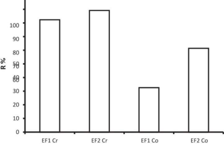
Fig. 10. Percentage of Cr (VI) and Co heavy metals retention (R%) by the Sm/Z6 UF membrane for the effluents EF1 and EF2 at pressure P = 3 bars.
rejectionwas96.12, 94.11 and 97.75% for color, turbidity and COD, respectively. The rejection of Cr (VI) was of 80% for EF1 and 90% for EF2, but much lower for Co (30% for EF1 and 60% for EF2) (Fig.10).
In fact, it is observed that at pressures above 3 bar, the metal rejection decreased due to the passage of pollutants through the pores of the membrane under the effect of pressure.
The experimental results indicate that the percentage of retention, both for Cr (VI) and Co decreases with pressure (Fig.11). Thus, it is worthy to notice that the efficiency of the retention of pollutants depends on the composition of the effluent and on the operating parameters.
Boricha and Murthy(2010) showed that the highest retention rate of chromium (83%) was observed at 10 bar. However, recentlyChoudhury et al.(2018), found a similar retention rate, at a lower pressure of 2 bars with a ceramic membrane of 3 nm pore size. The higher retention rates of heavy metals were related to the pore size and the interaction of the effluent with the membrane. Cr (VI) can exist in different ionic forms in the aqueous solution (HCrO−4 , CrO2−, Cr
2O2−)
depending on Cr (VI) concentration and solution pH (Cabatingan et al.,2001) and S.S (Chen et al.,2008). The pore size of
the membrane was determined as 3 to 6 nm and the hydratedradius of HCrO−4 1 (0.375 nm) is lower than the membrane pores. Therefore, size exclusion principle did not play a major role on Cr (VI) and Co ions retention. However, there is a possibility of the bonding between the lower radius ions with water molecules leading to the increase of its size which
can explain the high removal through the membraneAl Rashdi et al.(2013). In order to determine the interaction with the membrane, the point of zero charge (pHpzc ) was quantified using a zetameter. The pHpzc value found is around 1.7 or 1.8 (Fig.12).
Therefore, the membrane is positively charged for a pH< pHpzc and negatively charged for a pH>pHpzc . The pH of 6.2 for EF1and 2.9 for EF2
was for both effluents higher than the pHpzc . The anionic species such as HCrO−4 would thus have strong repulsion, which explains the relative
high rejection of the Cr ions (83% for EF1 and 89% for EF2).
For a pH of 2.9, the most dominant anionic species is HCrO−4 and for the pH of 6.2 there is coexistence of both anionic
species HCrO−4 and CrO2− ( according to the stability diagram in function with pH). The decrease of the rejection rate from 90% for EF2 to 80% for EF1 is explained by the phenomenon of ion exclusion.
Co exists in the form of Co2+ ions (De˘dečk and Wichterlová,1999;D e˘dečk et al.,2000,2002), which suggests thus that the difference in Co rejection
for both effluents can be explained by the electrostatic interaction with the membrane. The highest Co rejection rate is found for EF2 exhibiting a pH of 2.9 and thereby a low negative charge density charge.
Referring to the pHpzc of 1.8, the membrane is negatively charged. Therefore, the electrostatic interactions alone do not explain the retention of Co2+, the retention related to steric hindrance is to be taken into account mainly because of the complexity of the composition of the raw effluent,
which is very loaded in different types of anions and cations that can interact together (Table4).
The effect of the initial concentration of Co2+ on the rejection rate shows a decrease of the rejection with the decrease
of the concentration, the obtained values are of TR CO: 65% for EF2 (2.04 mg/L) and TR CO: 32% for EF1 (0.54 mg/L). This behavior confirms the results reported by (Zola et al.,2012).
Thus, it is worthy to notice that the heavy metal retention efficiency mainly depended on pH and the highest rejection rate was obtained near pHpzc .
4.1.3. Determination of fouling nature
Membrane fouling was caused by organic or inorganic compounds, bacteria, colloids, or suspended solids. Fouling can diminish the permeate flux and might influence the retention of numerous compounds. It can be reversible or irreversible. Reversible fouling can be removed readily by water rinsing or changing some process parameters, while irreversible fouling is difficult to remove and might require chemical cleaning (Tansel et al.,2000). Previous works proved that
Fig. 11. Percentage of retention of heavy metals (Cr (VI) and Co) with pressure (3–5 and 7 bar).
Fig. 12. Determination of the point zero charge (pHpzc ).
reversible and irreversible fouling can represent up to 18% and 26%–46% of permeate flux reduction, respectively (Van der Bruggen et al.,2005). In order to determinate the nature of the fouling; the resistance-in-series model can be used:
RT= Rm+ Rrev + Rrev (8)
where RT is the total filtration resistance which represents the distribution of the different partial resistances. Rm is the inherent hydraulic
resistance of a clean membrane (m−1 ), it was obtained by the determination of distilled water permeability. R
rev is mostly due to the concentration
polarization and deposition of retained substances on the membrane surface. It can be removed by simple water rinsing of the membrane after each filtration process. The Rirrev is the irreversible resistance due to the contributions of the fouling such as adsorption onto the membrane pores
and surface and pore blocking, and therefore, it is not removed by a simple distilled water rinsing. A specific cleaning is needed to found the initial performances of the membrane.
In our case the different resistance of the Sm/Z6 membrane is shown inTable5. Then, the dominant fouling mechanism can be determined from these results. It was established that Rrev > Rirrev, indicating that the decline of permeate flux is mainly due to reversible fouling for the UF membranes obtained.
≤ Fig. 13. Permeate flux versus pressure of unused and regenerated membrane Sm/Z6. Table 5
The different values of the resistances calculated for Sm/Z6 membranes.
Samples RT 1012 (m−1 ) Rm 1012 (m−1 ) Rrev 1012 (m−1 ) R
irr év 1012 (m−1 )
Sm/Z6 15,32 6,42 7 1,9
4.2. Membrane regeneration
The cost of UF depends on the membrane regeneration efficiency and on the cleaning process cost (Han et al.,2000). The regeneration of the membrane was studied at constant experimental parameters by considering a series of UF experiments.
The membrane regeneration was performed by a simple membrane rinsing with deionized water after each run. This procedure was repeated for four cycles.
The effectiveness of the regeneration was checked by the determination of the membrane water permeability which should be quite similar to that obtained with unused membraneFig.13). An almost total regeneration of the Sm/Z6 membrane was observed until the cycle 2 and then afterwards a slight loss of performance ( 10%) was observed. When the phenomenon of fouling occur, the chemical cleaning of the membrane becomes necessary to restore the initial membrane characteristics in terms of water permeability.
5. Conclusion
Four different membranes Sm/Z4, Sm/Z5, Sm/Z6 and Sm/Z7 with different number of layer deposited on the support were prepared using the L.B.L method. Textural property, membrane thickness and morphology of the membranes were obtained using BJH (Barret-Joyner-Halenda) method and SEM. Membranes sintered at an optimal temperature of 900 ◦C showed average pore size of 3 nm-13 nm for Sm/Z4, 2 nm–11 nm for Sm/Z5, 3 nm–5 nm for Sm/Z6, and 14 nm – 21 nm for Sm/Z7. The thickness of these membranes was 9.42 µm, 11.84 µm, 20.76 µm and 8.5 µm for Sm/Z4, Sm/Z5, Sm/Z6 and Sm/Z7 respectively.
The performance of this membrane for the treatment of electroplating industry wastewater was equally studied. The best performance was achieved at a pressure of 3 bar with a permeate flux of 59 L/h m2 for Sm/Z6. A quasi-total abatement of turbidity (< 1 NTU), and chemical oxygen demand
was recorded. A relatively high permeate flux value was maintained during filtration due to antifouling characteristics of the UF active layer. Results from the study of the membrane regeneration indicate that selectivity of the membrane for Cr and Co was preserved, even after a long duration of use. This observation was also recorded for the membrane flux.
Declaration of competing interest
The authors declare that they have no known competing financial interests or personal relationships that could have appeared to influence the work reported in this paper.
Acknowledgments
The authors would like to thank the ERANETMED program (SETPROpER), Tunisia for funding the entire research work. We are grateful to Prof. Feryal Akbal, Burcu Özkaraova, and Ayşe Kuleyin. Environmental Engineering Department Onkoduz Mayis UniversitySamsun, Turquie) for the provision of the zeolite raw material.
References
Al Rashdi, B.A.M.D., Johnson, J., Hilal, N., 2013. Removal of heavy metal ions by nanofiltration. Desalination 315, 2–17.
Aloulou, H., Bouhamed, H., Ghorbel, A., Ben Amar, R., Khemekhem, S., 2017. Elaboration and characterization of ceramic microfiltration membranes from natural zeolite: application to the treatment of cuttlefish effluents. Desalin. Water Treat. 1–9.
Aloulou, W., Hamza, W., Aloulou, H., Oun, A., Khemakhem, S., Jada, A., Chakraborty, S., Curcio, S., Ben Amar, R., 2018. Developing of titania-smectite nanocomposites UF membrane over zeolite based ceramic support. Appl. Clay Sci. 155, 20–29.
Banni, M., Jebali, J., Daubeze, M., Clerandau, C., Guerbej, H., Narbonne, J.F., 2005. Monitoring pollution in Tunisian coasts : application of a classification scale based on biochemical markers. Biomarkers 10, 105–116.
Bareera, M., Valentina, B., Sevde, U.O., Hanife, B., 2020. A study on behaviour, interaction and rejection of Paracetamol, Di clofenac and Ibuprofen (PhACs) from wastewater by nanofiltration membranes.http://dx.doi.org/10.1016/j.eti.2020.100641.
Barhoumi, S., Messaoudi, I., Deli, T., Saïd, K., Kerkeni, A., 2009. Cadmium bioaccumulation in three benthic fish species, Slaria basilisca, Zosterisessor ophicephalus, Solea vulgaris collected from the Gulf of Gabes in Tunisia. J. Environ. Sci. 21, 980.
Bhattacharya, M., Dutta, S.K., Skider, J., K.Mandal, M., 2014. Computation and experimental stady of chromium (VI) removal in direct contact membrane distillation. J. Membr. Sci. 450, 447–456.
Bhattacharya, P., Roy, A., Sarkar, S., Ghosh, S., Majumdar, S., Chakraborty, S., Mandal, A., Bandyopadhyay, S., 2013. Combination technology of ceramic microfiltration and reverse osmosis for tannery wastewater recovery. Water. Res. Ind. 3, 48–62.
Boricha, A.G., Murthy, Z.V.P., 2010. Preparation of N, O-carboxy methyl chitosan/celluloseacetate blend nanofiltration membrane and testing its performance in treating industrial wastewater. Chem. Eng. J. 157, 93–400.
Breida, M., Alami Younssi, S., Bouazizi, A., Achiou, B., Ouammou, M., El Rhazi, M., 2017. Nitrate removal from aqueous solution by γ -Al2O3 ultrafiltration membrane. HELIYON 2659.
Van der Bruggen, B., Cornelis, G., Vandecasteele, C., Devreese, I., 2005. Fouling of nanofiltration and ultrafiltration membranes applied for wastewater regeneration in the textile industry. Desalination 175, 111–119.
Cabatingan, L.K., Agapay, R.C., Rakels, J.L.L., Ottens, M., Van der Wielen, L.A.M., 2001. Potential of biosorption for the recovery of chromate in industrial wastewaters. Ind. Eng. Chem. Res. 40, 2302–2309.
Chen, S.S., Hsu, B.C., Ko, C.K., Chuang, P.O., 2008. Recovery of chromate from spent plating solutions by two-stage nanofiltration processes. Desalination 229, 147–155.
Chen, G., Liu, R., Shon, H.K.Y., Wang, J., Song, X.M., Li, He, T., 2017. Open porous hydrophilic supported thin-film composite forward osmosis membrane via co-casting for treatment of high-salinity wastewater. Desalination 405, 76–84.
Choudhury, P.R., Majumdar, S., Sahoo, G.C., Saha, S., Mondal, P., 2018. High pressure ultrafiltration CuO/ hydroxyethyl cellulose composite ceramic membrane for separation of Cr (VI) and Pb (II) from contaminated water. Chem. Eng. J. 336, 570–578.
Daramola, M.O., Aransiola, E.F., Ojumu, V.T., 2012. Potential applications of zeolite membranes in reaction coupling separation processes. Materials 5, 2101–2136.
Daramola, M.O., Sadare, O.O., Oluwasina, O.O., Iyuke, S.E., 2019. Synthesis and application of functi onalized carbon nanotube infused polymer membrane (f CNT/PSF/PVA) for treatment of phenol-containing wastewater. J. Membr. Sci. Res. 5, 310–316.
Daramola, M.O., Silinda, B., Masondo, S., Oluwasina, O.O., 2015. Polyether sulfone-sodalite (PES-SOD) mixed matrix membranes: Prospect for acid mine drainage (AMD) treatment. J. Southern African Inst. Min. Metall. 115, 1221–1228.
De˘dečk, J., Kaucký, D., Wichterlová, B., 2000. Co2+ ionsiting in pentasil-containing zeolites, Part 3. Co2+ ion sites and their occupation in ZSM-5: aVIS diffuse reflectance
spectroscopy study. Micropor. Mesopor. Mater. 35–36, 483–494.
De˘dečk, J., Čapek, L., Kaucký, D., Zobalíck, Z., Wichterlová, B., 2002. Siting and distribution of the coions in beta zeolite: A UV–VIS-NIR and FTIR study. J. Catal. 211, 198–207. De˘dečk, J., Wichterlová, B., 1999. Co2+ ion siting in pentasil-containing zeolites. I. Co2+ ion sites and their occupation in mordenite. A vis-NIR diffuse reflectance spectroscopy study. J.
Phys. Chem. B. 103, 1462–1476.
Hamza Chaffai, A., Cosson, R.P., Amiard-Triquet, C., El Abed, A., 1995. Physico-chemical froms of storge of metals (Cd, Cu and Zn) and metallothionein-like proteins in gills and liver of marine fish from Tunisia coast : ecotoxicological consequences. Comp. Biochem. Physiol. C 111, 329–341.
Han, W., Gregor, H.P., Pearce, E.M., 2000. Interaction of proteins with ultrafiltration membranes: Development of a nonfouling index test. J. Appl. Polym. Sci. 77, 1600–1606.
Hashim, M.A., Mukhopadhyay, S., Sahu, J.N., Sengupta, B., 2011. Remediation technologies for heavy metal contaminated ground water. J. Environ. Manag. 92, 2355–2388.
Kasemset, S., Wang, L., He, Z., Miller, D.J., Kirschner, A., Freeman, B.D., Sharma, M.M., 2017. Influence of polydopamine dep osition conditions on hydraulic permeability, sieving coefficients, pore size and pore size distribution for a polysulfone ultrafiltration membrane. J. Membr. Sci. 522, 100–115.
Kessabi, K., Kerkani, A., Saïd, K., Messaoudi, I., 2008. Involvement of Cd bioacumulation in spinal deformities occurrence in natural populations of mediterranean killifish. Biol. Trace Elem. Res. 128, 72–81.
Kessabi, K., Navarro, A., Saïd, K., Messaoudi, I., Pifia, B., 2010. Evaluation of environnemental impact on natural populations of the mediterranean killifish aphanius fasciatus by quantitative RNA biomarkers. Mar. Environ. Res. 70, 327–333.
Khemakhem, S., Ben Amar, R., Larbot, A., 2007. Synthesis and characterization of a new inorganic ultrafiltration membrane composed entir ely of Tunisian natural illite clay. Desalination 206, 210–214.
Khemakhem, M., Khemakhem, S., Ben Amar, R., 2013. Emulsion separation using hydrophobic grafted ceramic membranes by air gap membrane distillation process. Colloids Surf. A 436, 402–407.
Khemakhem, S., Larbot, A., Ben Amar, R., 2009. New ceramic microfiltration membranes from Tunisian natural materials: application for the cuttlefish effluents treatment. Ceram. Int. 35, 55–61.
Kumar, G.P., Kumr, P.A., Chakraborty, S., Ray, M., 2007. Uptake and desorption of copper ion using functionalized polymer coated silica gel in aqueous environnement. Sep. Purif. Technol. 57, 47–56.
Lastra, A., Gómez, D., Romerob, J., Francisco, J.L., Luque, S., Álvarez, J.R., 2004. Removal of metal complexes by nanofiltration in a TCF pulp mill: technical and economic feasibility. J. Membr. Sci. 242, 97–105.
Mahmoud, M.E., Yakout, A.A., Halbas, A.M., Osman, M.M., 2016. Remediation of Cr (VI) via combined self-redaction and adsorption by chemically modified carbon sorbents. Turk. J. Chem. 40, 906–920.
Masmoudi, S., Larbot, A., El Feki, H., Ben Amar, R., 2006. Use of ultrafiltration membranes with apatite for the treatment of cuttlefish effluent. Desalination 200, 335–336.
Mathaba, M.J., Daramola, M.O., 2019. Synthesis and performance evaluation of PES/chitosan membranes coated with polyamide for acid mine drainage treatment. Sci. Rep. 9, 17657.http://dx.doi.org/10.1038/s41598-019-53512-8.
McBain, J.W., Kistler, S.S., 1931. Ultrafiltration as a test for colloidal constituents in aqueous and nonaqueous systems. J. Phys. Chem. 35, 130–136.
Mohd Ridhwan, A., Mohd Hafiz Dzarfan, O., Mohd Hafiz, P., Mohammad Arif Budiman, P., Mukhlis, A.R., Juhana, J., 2017. A fabrication of a low-cost zeolite based ceramic membrane via phase inversion and sintering technique Malaysian. J. Anal. Sci. 21, 391–401.
Mondal, P., Bhowmick, S., Chatterjee, D., Figoli, A., Van der Bruggen, B., 2013. Remediation of inorganic arsenic in ground water for safe water supply: a critical assessment of technological solutions. Chemosphere 92, 157–170.
Muthukrishnan, M., Guha, B.K., 2008. Effect of pH on rejection of hexavalent chromium by nanofiltration. Desalination 219, 17 1–178. Muthumareeswaran, M.R., Alhoshan, M., Agarwal, G.P., 2016. Ultrafiltration membrane for effective removal of chromium ions from potable water.
Sci. Rep. 7, 41423.http://dx.doi.org/10.1038/srep41423.
Panayotova, T., Dimova Todorova, M., Dobrevsky, I., 2007. Purification and reuse of heavy metals containing wastewaters from electroplating plants. Desalination 206, 135–140.
Pugazhenthi, G., Sachan, S., Kishore, N., Kumar, A., 2005. Separation of chromium (VI) using modified ultrafiltration charged carbon membr ane and its mathematical modeling. J. Membr. Sci. 254, 229–239.
Quist-Jensen, C.A., Macedonio, F., Horbez, D., Drioli, E., 2017. Reclamation of sodium sulfate from industrial wastewater by using membrane distillation and membrane crystallization. Desalination 401, 112–119.
Rameeetse, M.S., Aberefa, O.A., Daramola, M.O., 2019. Synthesis and characterization of PSF/PES composite membranes for use in oily wastewater treatment. J. Phys.: Conf. Ser. 1378, 022013.http://dx.doi.org/10.1088/1742-6596/1378/2/022013.
Rastgar, M., Shakeri, A., Bozorg, A., Salehi, H., Saadattalab, V., 2017. Impact of nanoparticles surface characteristics on pore structure and performance of forward osmosis membranes. Desalination 11, 13210.
Sachdeva, S., Kumar, A., 2008. Synthesis and modeling of charged ultrafiltration membranes of poly (styrene-co-divinyl benzene) for the separation of chromium (W). Ind. Eng. Chem. Res. 47, 4236–4250.
Saffaj, N., Mamouni, A., Laknifli, R.A., Mouna, A., Younssi, S.A., Albizane, A., 2010. Efficiency of ultrafiltration ceramic membranes for toxic elements removal from wastewaters (nd). St. Cerc. St. CICBIA 11, 243–254.
Saffaj, N., Persin, M., Alami Younssi, S., Albizane, A., Bouhria, M., Loukili, H., Dach, H., Larbot, A., 2005. Removal of salts and dyes by low ZnAl2O4–TiO2 ultrafiltration membrane
deposited on support made from raw clay. Sep. Purif. Technol. 47, 36–42.
Sanyal, O., Sommerfeld, A.N., Lee, I., 2015. Design of ultrathin nanostructured polyelectrolyte-based membranes with high perchlorate rejection and high permeability. Sep. Purif. Technol. 145, 113–119.
Steenkamp, G.C., Keizer, K., Neomagus, H.W.J.P., Krieg, H.M., 2002. Copper (II) removal from polluted water with alumina/chitosan composite membranes. J. Membr. Sci. 19, 147–156.
Tahri, N., Jedidi, I., Ayadi, S., Cerneaux, S., Cretin, M., Ben Amar, R., 2016. Preparation of an asymmetric microporouscarbon membrane for ultrafiltration separation : application to the treatment of industrial dyeing effluent. Desalin. Water. Treat. 1–16.
Tahri, N., Jedidi, I., Cerneaux, S., Cretin, M., Ben Amar, R., 2013. Development of an asymmetric carbon microfiltration membrane: Application to the treatment of industrial textile wastewater. Sep. Purif. Technol. 118, 179–187.
Tansel, B., Bao, W.Y., Tansel, I.N., 2000. Characterization of fouling kinetics in ultrafiltration systems by resistancesin series model. Desalination 129, 7–14.
Wan, H., Briot, N.J., Saad, A., Ormsbee, L., Bhattacharyya, D., 2017. Pore functionalized PVDF membranes with in-situ synthesized metal nanoparticles: Material characterization, and toxic organic degradation. J. Membr. Sci. 530, 147–157.
Zhu, W.P., Gao, J., Sun, S.P., Zhang, S., Chung, T.S., 2015. Poly (amidoamine) dendrimer (PAMAM) grafted on thin film composite (TFC) nanofiltration (NF) hollow fiber membranes for heavy metal removal. J. Membr. Sci. 487, 117–126.
Zola, A.S., Barros, M.A.S.D., Sousa-Aguiar, E.F., Arroyo, P.A., 2012. Determination of the maximum retention of cobalt by ion exchange in H-zeolites. Braz. J. Chem. Eng. 29, 385–39.