HAL Id: cea-01871423
https://hal-cea.archives-ouvertes.fr/cea-01871423v2
Submitted on 27 May 2020
HAL is a multi-disciplinary open access
archive for the deposit and dissemination of
sci-entific research documents, whether they are
pub-lished or not. The documents may come from
teaching and research institutions in France or
abroad, or from public or private research centers.
L’archive ouverte pluridisciplinaire HAL, est
destinée au dépôt et à la diffusion de documents
scientifiques de niveau recherche, publiés ou non,
émanant des établissements d’enseignement et de
recherche français ou étrangers, des laboratoires
publics ou privés.
UNII-MAC protocol: Design and evaluation for 5G
ultra-dense small cell networks operating in 5 GHz
unlicensed spectrum
Rida Chall, Benoit Miscopein, Dimitri Kténas
To cite this version:
Rida Chall, Benoit Miscopein, Dimitri Kténas. UNII-MAC protocol: Design and evaluation for 5G
ultra-dense small cell networks operating in 5 GHz unlicensed spectrum. Computer Communications,
Elsevier, 2018, 126, pp.11-27. �10.1016/j.comcom.2018.04.005�. �cea-01871423v2�
UNII-MAC protocol: Design and evaluation for 5G ultra-dense small cell
networks operating in 5 GHz unlicensed spectrum
Rida El Challa,∗, Benoit Miscopeina,∗, Dimitri Kt´enasa,∗
a
CEA-Leti Minatec, 17 rue des Martyrs, 38054 Grenoble Cedex 9, France
Abstract
Ultra-densification and efficient spectrum utilization are key features for the next 5G wireless networks to address the well-known challenges of high capacity demands and mobile data traffic explosion. In this article, a physical layer and a medium access control (MAC) sublayer are presented for small cells to operate in the 5 GHz unlicensed national information infrastructure (UNII) band. The physical layer is based on filter bank multi-carrier modulation able to achieve better spectral efficiency and access flexibility. The MAC protocol is based on a beacon-enabled superframe consisting of scheduled and contention access schemes. The proposed UNII-MAC design relies on a listen-before-talk (LBT) procedure in order to comply with ETSI regulations and to fairly coexist with neighboring systems sharing the same band. The performance of the UNII-MAC is then evaluated in dense indoor/outdoor deployment scenarios under various parameters and traffic patterns. Moreover, the coexistence between UNII-MAC and WiFi systems is reported. Based on the obtained results, we provide recommendations for 5G small cell deployment in dense environments. Keywords: 5G, dense small cell networks, 5 GHz UNII band, FBMC, multiple access MAC design, LBT, contention access, scheduled access, CSMA/CA
1. Introduction
Nowadays, the exponential growth of mobile data traffic and the increased demands for higher data rate, reliability, and diverse quality-of-service (QoS) requirements cause significant challenges for the existing wireless networks. Fifth generation (5G) wireless network has been therefore evolved to cope with these challenges and to support the wide ranges of emerging applications [1]. These applications include enhanced mobile broadband, ultra-reliable and low-latency communications, and massive machine-type communica-tions [2]. In this trend, enormous efforts have been made to identify various enabling technologies for 5G networks, capable of handling mobile data demands expected by 2020 [3, 4]. A recent overview of the main challenges and 5G technologies has been presented in [5, 6, 7]. The key aspects related to the flexibility and autonomy of 5G networks have been elaborated regarding architecture, virtualization, medium access control (MAC) and physical (PHY) layers [6]. Meanwhile, a framework for developing flexible waveform, numerology, and frame design strategies has been addressed in [7].
Driven by the 5G requirements definition work, it is now widely accepted that a massive network capacity improvement can be obtained through three main drivers which are network ultra-densification, efficient use of spectrum, and advanced modulation techniques. Ultra-densification has been considered as an emerging solution to exploit the spatial reuse of the spectrum resource through deploying a large number of small cells with reduced coverage and low power, allowing more capacity improvements. At the same time, the exploitation of heterogeneous resources in the available licensed, lightly-licensed and unlicensed bands is
∗Corresponding author
Email addresses: rida.elchall@cea.fr(Rida El Chall ), benoit.miscopein@cea.fr (Benoit Miscopein ),
widely under investigation; the spectrum resources being possibly used assuming traffic steering or aggre-gation mechanisms. Moreover, the requirement for more spectrum flexibility and relaxed synchronicity has encouraged the study of several carrier waveforms in last few years [8, 9, 10] such as filter bank multi-carrier (FBMC). Indeed, FBMC technique offers a large number of advantages compared to the widely-used orthogonal frequency division multiplexing (OFDM) system in terms of improved spectral efficiency, low out-of-band emission and robustness to asynchronous multi-user communication, thanks to the time-frequency localized pulse shaping [10]. An overview and a detailed comparison of 5G waveform candidates have been presented in [11, 12].
On the other hand, the increasing demand for additional spectrum leads to the development of dynamic spectrum sharing and channel access mechanisms in order to alleviate the scarcity of spectrum bands and to improve network capacity. A comprehensive survey of the existing spectrum sharing methods for the coexistence of various radio frequency systems has been reported in [13]. The main challenge of shared spectrum access is the coexistence. Considering this point, it is required that any deployed system complies with frequency policies and regulatory requirements in order to protect the primary system and to fairly coexist with other pre-existing systems. In particular, the usage of 5 GHz unlicensed national information infrastructure (UNII) spectrum for data offloading has recently attracted considerable interest from research and industrial fields [14]. In this regard, several long-term evolution (LTE)-based technologies operating on the unlicensed band are currently developed by the 3GPP depending on the deployment scenario and the region [15]. The main methods for using LTE in the 5 GHz unlicensed bands are LTE-Unlicensed (LTE-U) [16, 17] and licensed assisted access (LAA) [18, 19]. LTE-U and LAA use carrier aggregation between a primary LTE licensed carrier and an unlicensed secondary carrier assisted by the licensed carrier. As an alternative solution, LTE-WLAN aggregation (LWA) considers the aggregation of LTE in licensed band and WiFi in unlicensed band simultaneously. Multefire is another LTE-based technology for a small cell operating solely in unlicensed spectrum without LTE licensed anchor [20]. The important topic that is currently being investigated is the fair coexistence of LTE and WiFi in the unlicensed band [21, 22]. LTE-U uses an adaptive on/off duty cycle as a mechanism to share the medium with existing WiFi networks. This solution can be adopted for deployment options and regions with no listen-before-talk (LBT) regulation, e.g. Korea, USA, China, etc [16]. The LAA approach is considered in the countries with LBT requirement, e.g., Europe and Japan, where clear channel assessment (CCA) is performed to determine channel availability before transmission [18, 19]. ETSI provides two options for LBT schemes: frame-based equipment (FBE) and load-based equipment (LBE) [14]. LBE is adopted in LAA since it uses a contention scheme similar to carrier sense multiple access/collision avoidance (CSMA/CA) approach in WiFi systems and has been proven to provide better coexistence results in practical deployment [21, 22].
Regarding the MAC aspects, 3GPP specifies a MAC protocol that includes MAC architecture, MAC entities, and MAC procedures in order to handle data traffic on various transport channels [23]. Similarly, a 5G MAC protocol specification has been presented in [24] to support additional services and mapping functions between layers. These MAC protocols are initially designed for a system operating in the licensed spectrum. Besides this, many contributions and systems have been specified or standardized to enable broadband wireless area networks, the main one being WiFi. IEEE 802.11ax working group is currently developing a new amendment for a high efficiency wireless local area network in high-density scenarios [25] as the existing WiFi versions are still not able to provide throughput improvements in dense deployment. Consequently, in the perspective of deploying and managing dense 5G small cell networks, PHY and MAC layer schemes need to be further developed and adapted to fulfill the challenging application requirements. These schemes should provide efficient channel access and better spectrum utilization for small cells able to operate in the 5 GHz unlicensed band with fair coexistence with incumbent systems. Note that IEEE 802.11ax relies on the legacy OFDM WiFi physical layer. An additional area of literature focuses on the PHY and MAC layer solutions able to operate in lightly-licensed bands. More specifically, the ECMA-392 standard has been developed for wireless devices to operate in the TV white space[26]. The specified MAC sublayer relies on a beacon-enabled superframe based on CSMA/CA protocol, which allows scheduled and uncoordinated access modes. This MAC is also the baseline of IEEE 1900.7 protocol (radio interface for white space dynamic spectrum access radio systems supporting fixed and mobile Operation)[27] but this standard specifies an FBMC physical layer. However, these standards are limited to a single channel access at a time and do
not support broadband access for dense deployment. Similarly, IEEE 802.15.4 standard specifies a MAC protocol based on beacon superframe structure, but for low rate wireless personal area network [28]. In [29], we have proposed a MAC design which targets the aforementioned three main drivers of 5G. In that paper, the proposed design complies with the extended dynamic spectrum access (eDSA) framework proposed by SPEED-5G project [30] but the MAC was only investigating the LBE access scheme while the FBMC physical layer was very briefly described; also the performance evaluation was limited to restricted cases like downlink full buffer traffic in outdoor scenarios. In this contribution, we extend the study with an in-depth investigation of PHY and MAC layer aspects, the latter being able to support both channel access modes (FBE, LBE). As well, the performance of the MAC protocol referred to as UNII-MAC in the sequel, are evaluated in a much broader and more practical scope. More specifically, UNII-MAC is based on beacon-enabled MAC protocol, assuming an FBMC physical layer. The spectral confinement of FBMC signal is exploited at MAC layer to facilitate the resource allocation in uplink and asynchronous multi-user access. The beacon-enabled superframe consists of scheduled and contention access schemes where data, control and command frames are sent within time slots. In addition, UNII-MAC relies on an LBT procedure to enable small cell operation in the 5 GHz shared spectrum while coexisting with other incumbent systems and fulfilling the regulatory requirements. At this point, we investigate the impact of various channel access schemes of LBT, namely FBE and LBE, on dense deployment scenarios. The performance of UNII-MAC is then evaluated under various PHY/MAC parameter settings and coexistence cases. In particular, the impact of varying network density, energy detection threshold, and traffic types is widely investigated in indoor/outdoor deployment scenarios. The main objective is to give a complete and comprehensive study of the functionality and the performance of UNII-MAC system in order to provide recommendations in setting the parameters for real small cell deployment.
The remainder of this paper is organized as follows. Section 2 presents the physical layer, starting by describing FBMC waveform and the key features of FBMC compared to OFDM exploited at the MAC layer. FBMC transceiver assumptions and PHY parameters are next presented. In Section 3, a detailed description of the MAC protocol is considered. The superframe structure, the multiple access procedures, and LBT access modes are presented. Section 4 deals with the deployment scenarios, simulation assumptions, and parameters. The performance of the proposed design is then investigated in Section 5. Finally, the conclusions are given in Section 6.
2. Physical layer description
This section firstly reviews the fundamental characteristics of FBMC waveform and its impact on the MAC design. Then, the assumptions on FBMC transceiver are presented, followed by describing FBMC PHY parameters.
2.1. FBMC overview and characteristics for MAC design
OFDM is the multi-carrier modulation widely adopted in current wireless communication systems. The main factors for using OFDM rely on its efficient implementation based on inverse and fast Fourier trans-form (IFFT/FFT), robustness to frequency selective channels and simple equalization. OFDM technique consists in transmitting the modulated symbols over multiple orthogonal subcarriers through the use of a rectangular pulse in the time domain. A cyclic prefix (CP) larger than the delay spread of the channel is then inserted in order to avoid the inter-symbol interference (ISI) in selective channels. However, OFDM presents several limitations for the future wireless network. First, OFDM requires perfect time and fre-quency synchronizations in order to avoid inter-carrier interference (ICI) and to preserve the orthogonality of subcarriers, which is very difficult to guarantee in uplink multi-user systems. In addition, it suffers from high adjacent channel leakage ratio (ACLR) due to the use of sinc filter; the first side lobe is only 13 dB lower than the main lobe. The peak-to-average power ratio (PAPR) is another drawback of multi-carrier systems resulting from the combination of independent subcarriers.
Several alternative multi-carrier techniques are therefore proposed to overcome OFDM limitations such as FBMC [12] and block-filtered (BF)-OFDM [31]. Herein, FBMC modulation is considered without loss of
generality. In FBMC, a set of parallel data symbols is transmitted through a bank of modulated filters that provide extremely low adjacent channel leakage and very sharp frequency confinement of the signal [10, 32]. The prototype filter is characterized by its overlapping factor K, which is the number of multi-carrier symbols that overlap in the time domain. The overlapping factor K has an impact on determining the optimum spectrum utilization, the level of adjacent channel leakage and the residual inter-symbol interference. In particular, offset quadrature amplitude modulation (OQAM) is used with prototype filter based on Nyquist constraints in order to guarantee orthogonality between adjacent symbols and adjacent carriers, providing maximum spectral efficiency [10].
Figure 1 shows the power spectral density (PSD) of OFDM and FBMC signals for several values of K. The multi-carrier signal consists of two frequency blocks of 900 kHz corresponding to 5 resource blocks (RBs) of 180 kHz spaced by an unallocated RB. The curves show that OFDM leads to the larger out-of-band emissions. The better spectral containment of the signal is achieved using FBMC with K = 4, where the leakage is lower than -60 dBc. For K = 3, the spectral location is still very good, meanwhile for K = 2 the out-of-band leakage increases significantly, and it is only 10 dB lower than OFDM.
−2 −1.5 −1 −0.5 0 0.5 1 1.5 2 −60 −50 −40 −30 −20 −10 0 Frequency [MHz]
Power spectral density [dBc/Hz]
OFDM FBMC K=2 FBMC K =3 FBMC K =4
Figure 1: Power spectral density of OFDM and FBMC with several values of K
Thanks to the excellent spectral localization of the waveform, the FBMC physical layer can be exploited at MAC layer in order to optimize medium access through the following characteristics:
• Relaxed synchronicity: In CP-OFDM, simultaneous transmissions coming from different users in
con-tiguous bands have to respect a timing misalignment smaller than the CP length in order to avoid ICI, which is in practice very hard to achieve. By contrast, FBMC system achieves signal separation through filtering and provides a very small level of adjacent carrier interference if a guard band of at least one subcarrier spacing is introduced [33]. This avoids the need for strict time and carrier synchronization and allows asynchronous uplink communications on contiguous bands.
• Efficient spectrum utilization: The extremely low adjacent channel leakage ratio makes FBMC perfect
choice for efficient use of the spectrum. The MAC layer can thus efficiently manage the allocation of resource blocks, even if they are fragmented and spread on the band. Moreover, the insertion of CP is not required leading to more spectrum utilization.
• Relaxed uplink power control: Along the same idea of very low ACLR, the uplink signal in contiguous
bands can be transmitted without a strict power control. Indeed, provided that ACLR is more than 60 dB, two simultaneous signals on contiguous channels can arrive on a small cell with a very large difference of uplink received power.
2.2. FBMC transceiver assumptions
FBMC implementation considers the design of the prototype filter either in time or frequency domain using a polyphase network (PPN) or frequency spreading (FS) technique, respectively [10, 34]. In this work, FS-FBMC implementation is assumed since it provides perfect equalization of the transmission channel and maximizes the signal-to-noise ratio (SNR) in the receiver. The block diagram of FS-FBMC transmitter and receiver is depicted in Figure 2.
S/P OQAM
modu-lation
Freq.
Spreading IFFT Overlap
& sum Input data stream Output stream Decimati on & P/S One tap per
carrier equalizer FFT Sliding window points selection Filtering Transmitter Receiver
Figure 2: FS-FBMC block diagram for the transmitter and receiver
FS technique consists in spreading the OQAM symbols over P carriers, where P = 2K−1, using the frequency domain pulse response filter. An IFFT of size KN is then applied to the output samples, where N denotes the total number of subcarriers. The output is accumulated with the following IFFT output data stream delayed by N/2 through the overlap and sum module. Once the transient period is over, 2K of the KN -IFFT output samples are added together at any given time. At the receiver, the reverse operation is performed where a sliding window is first used to select KN points every N/2 samples. The FFT is then applied to the KN selected points. A single tap equalizer is used followed by the filtering with the prototype matched filter. Performance studies show that the frequency sampling process of FS-FBMC allows to reach the same level of bit error rate (BER) performance of LTE when the FFT size is reduced by a factor of K, i.e. the subcarrier spacing is increased by a factor K [33]. This feature is exploited to define FBMC parameters as presented in the next section. More details about the FBMC modulation and the filter coefficients can be found in [10], whereas implementation issues are presented in [12, 35].
2.3. FBMC PHY parameters
To support the MAC design, an FBMC physical layer has been designed to operate in the 5 GHz unlicensed band, where 10 and 20 MHz wide carriers can be allocated for broadband transmission according to the parameters specified in Table 1. The baseline for the definition of this FBMC PHY is the physical layer of LTE, which is based on CP-OFDM. In terms of numerology, the LTE PHY relies on an FFT of 1024 and 2048, an inter-carrier spacing of 15 kHz and a sampling frequency of 15.6 MHz and 30.72 MHz for 10 and 20 MHz channels, respectively. As previously stated, the FS property allows reducing the size of the FFT by a factor of K = 4 as shown in Table 1. For example, in the case of 20 MHz bandwidth, the total number of subcarriers is set to 512 with 60 kHz subcarrier spacing and 180 kHz resource block of 3 subcarriers. We note that reducing the FFT size by a factor of K = 4 reduces the time duration of FBMC symbol and the complexity of FFT implementation. Moreover, the PAPR is reduced, leading to almost the same PAPR performance of single-carrier frequency-division multiple access (SC-FDMA), which presents another advantage for uplink communication as reported in [12]. Another important advantage of FBMC is the spectrum efficiency improvement of approximately 10% compared to LTE. Indeed, in the case of
LTE, the 10 MHz and 20 MHz channels are occupied up to 9 MHz and 18 MHz, respectively. However, these channels are occupied up to 9.9 MHz and 19.8 MHz using FBMC. This is due to the absence of CP and the very low interference between adjacent channels if a small guard band equal to one subcarrier spacing is considered [33].
Table 1: FBMC parameters for 10 and 20 MHz channel bandwidth
Parameter 10 MHz band 20 MHz band
FFT size N 256 512 Active subcarriers Nc 165 330 Subcarrier spacing ∆f [kHz] 60 60 Overlapping factor K 4 4 Bandwidth B [MHz] 9.9 19.8 Resource block RB [kHz] 180 180 Number of RBs 55 110 Sampling Freq. Fs [MHz] 15.36 30.72
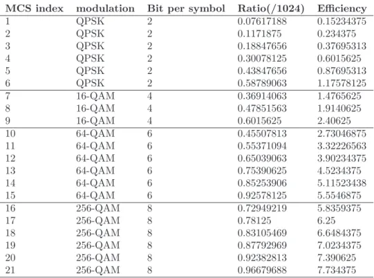
Similarly to LTE system, various modulation and coding schemes (MCSs) are considered, supporting QPSK, 16-QAM, 64-QAM and 256-QAM modulations as listed in Table 2. They have been derived from LTE specifications, using the same channel coding methodology and extending the list of supported modulations to 256-QAM. For this particular modulation, the values of the ratio parameter have been obtained by extrapolating the LTE values [36].
Table 2: Modulation and coding schemes of UNII-MAC
MCS index modulation Bit per symbol Ratio(/1024) Efficiency
1 QPSK 2 0.07617188 0.15234375 2 QPSK 2 0.1171875 0.234375 3 QPSK 2 0.18847656 0.37695313 4 QPSK 2 0.30078125 0.6015625 5 QPSK 2 0.43847656 0.87695313 6 QPSK 2 0.58789063 1.17578125 7 16-QAM 4 0.36914063 1.4765625 8 16-QAM 4 0.47851563 1.9140625 9 16-QAM 4 0.6015625 2.40625 10 64-QAM 6 0.45507813 2.73046875 11 64-QAM 6 0.55371094 3.32226563 12 64-QAM 6 0.65039063 3.90234375 13 64-QAM 6 0.75390625 4.5234375 14 64-QAM 6 0.85253906 5.11523438 15 64-QAM 6 0.92578125 5.5546875 16 256-QAM 8 0.72949219 5.8359375 17 256-QAM 8 0.78125 6.25 18 256-QAM 8 0.83105469 6.6484375 19 256-QAM 8 0.87792969 7.0234375 20 256-QAM 8 0.92382813 7.390625 21 256-QAM 8 0.96679688 7.734375
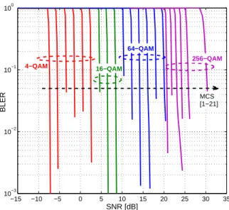
Figure 3 presents the block error rate (BLER) curves as a function of the SNR for different MCSs using turbo codes in additive white Gaussian noise (AWGN) channel of 20 MHz bandwidth with FBMC modulation. These curves are obtained using link level simulation (i.e. point-to-point simulation) and can be integrated as look-up tables (LUTs) into the system level simulator.
−15 −10 −5 0 5 10 15 20 25 30 35 10−3 10−2 10−1 100 SNR [dB] BLER MCS [1−21] 4−QAM 16−QAM 64−QAM 256−QAM
Figure 3: BLER vs. SNR curves for 20 MHz using turbo codes for various MCSs in AWGN channel with FBMC
3. UNII-MAC description
This section presents UNII-MAC which has been designed for 5G small cells, capable of supporting broad-band transmission in the 5 GHz unlicensed broad-band. Compared to the state-of-the-art of PHY/MAC sys-tems [23, 26, 27], this design allows a time division duplex (TDD) scheduled transmission for dense deploy-ment through an efficient multiple access scheme and it incorporates an LBT procedure to comply with ETSI regulatory requirements in the 5 GHz band [14]. The spectral confinement of FBMC is exploited first to enable the relaxed synchronicity constraint of uplink multiple access, thus lowering the signaling overhead, and secondly to avoid interference coming from inter-channel leakage in dense deployments. In what follows, the superframe structure, as well as the main functionalities of the MAC, are provided. 3.1. Superframe structure
The MAC design is based on a beacon-enabled superframe, that specifies a combination of contention and scheduled access schemes. The basic timing structure for frame exchange is the superframe in a master-slave operation mode, with the small cell (SC) being the master of user equipment (UE) within the radio range. More specifically, the superframe consists of a beacon period, a contention free period (CFP), a contention access period (CAP) and an idle period as illustrated in Figure 4. The length of the active superframe part is the channel occupancy time (COT) that is subdivided into multiple access time slots. The slot length and the number of slots can be adapted depending on the traffic type and channel load. In this work, a slot length of 1 ms is assumed without loss of generality, similarly to transmission time interval in LTE system. In the beacon period, the SC broadcasts a beacon frame that spans the whole band during a time slot. The beacon carries the control information to synchronize UEs in the network and to manage RB allocation and UE requests. In other words, the beacon includes control information elements (IEs) about the small cell identifier, superframe format, downlink/uplink (DL/UL) scheduled resources and operating channel. Upon reception of a beacon, UEs can request to associate with the SC, remaining associated until either several consecutive beacons are lost or disassociation request is initiated by UE or SC.
CFP is the scheduled access period, especially allocated for downlink and uplink data communications and composed of an adaptive number of time slots. The allocation of resources should be assigned to the UEs issuing reservation requests (RREQs) for downlink or uplink traffic in a previous superframe. The SC, based on the UE priority, QoS requirements, and the availability of resource will allocate a dedicated resource block to the UE. All subsequent beacon frames will contain the CFP DL/UL IE defining UE address, allocated RB (slot and frequency) and the assigned MCS. Upon receiving the beacon with the CFP descriptor, the
UE will send or receive data at the scheduled RBs, accordingly. It should be mentioned here that traffic may be also initiated by the SC by adding a paging flag in the beacon in order to notify the UE about a pending service. CAP Freq. CFP B e a c o n Scheduled uplink access Scheduled downlink access S u b -c h a n n e ls Idle Period
Channel occupancy time
A C K
Superframe duration
time
Figure 4: The structure of MAC superframe for broadband access in 5 GHz
The CAP is dedicated to control and command frames sent by UEs such as association requests, paging acknowledgment (PACK), ACK, NACK, channel quality indicator (CQI) reports and service establish-ment requests (RREQ). During this period, UEs use a contention-based random access, e.g. multi-channel CSMA/CA, as explained in the next section. On the other hand, control information, e.g. CQI, ACK, may be multiplexed with data in an uplink CFP slot when an active UE has both scheduled uplink and downlink traffic, thus allowing more flexibility in resource allocation. As far as scheduled uplink traffic is concerned, the SC may configure an ACK slot at the end of the CAP in order to send grouped acknowledgments, if any, for the uplink data received in the CFP.
At the end of the superframe, an idle period is considered that can be advantageously used by SCs to sense the channel and feed the spectrum manager with sensing report accordingly. It is interesting to note that the superframe structure can be dynamically adjusted depending on the traffic type and network load. Indeed, the length of the CFP can be tuned to support a given traffic profile like a possible traffic imbalance between uplink and downlink. Alternatively, the CAP duration can be also tuned to provide a better reliability to ACK and CQI updates when the number of active UEs is getting large.
3.2. Multiple access
In the proposed UNII-MAC design, multiple access schemes are supported in both time and frequency domains in CFP and CAP. Thus, compared with the conventional access schemes [23, 26, 27, 28], the time division multiple access in the beacon-enabled structure and the frequency division multiple access are both exploited to enable an efficient and dynamic share of the allocated spectrum.
In the CFP, multiple access (MA) is based on the OFDMA-like approach for both uplink and downlink channels, using the same concept of RB allocation of LTE systems but applied to FBMC modulation, referred to as FBMC-MA. In OFDMA and FBMC-MA, each UE is allocated a subset of subcarriers or RBs. To prevent ICI, the received signals must be perfectly synchronized. For downlink traffic, all the subcarriers are transmitted from the small cell and hence can be easily synchronized at the receiver side. However, synchronization is not trivial for the uplink where a number of UEs are transmitting separately. SC-FDMA has been considered for this purpose in LTE system. However, the filtering capability of FBMC with the aforementioned guard interval constraint enables asynchronous transmissions as discussed in Section 2. Uplink resource allocation can be done quite straightforwardly by the small cell using FBMC-MA scheme for both uplink and downlink communication. In this MAC, the SC scheduler is in charge of allocating both uplink and downlink resource blocks to active UEs, assuming the same kind of schedulers as those used in LTE, based on RB of 180 kHz (i.e. 3 active subcarriers). Figure 5 depicts multiple access schemes on the superframe, for both scheduled and contention access periods.
As previously mentioned, the multiple access in the CAP is based on multi-channel contention scheme. Since this period is dedicated to control and command traffic with small frame sizes, a reduced channel
bandwidth of 1.08 MHz is considered. The CAP is therefore subdivided into several sub-channels of 1.08 MHz bandwidth. Thus, 9 sub-channels and 18 sub-channels are assumed available for a system bandwidth of 10 MHz and 20 MHz, respectively. Each elementary sub-channel is therefore composed of 18 total subcarriers of 60 kHz (i.e. 6 resource blocks of 180 kHz). In order to avoid the interference between uplink users on adjacent sub-channels, one subcarrier is considered as guard band (Section 2), yielding 17 active subcarriers and one inactive subcarrier. UEs attempt to access the channel both in time and frequency domains using a multi-channel CSMA/CA algorithm. According to this protocol, a UE wishing to transmit a packet should perform channel sensing to identify the set of idle sub-channels. If all sub-channels are busy, UE defers access until a sub-channel becomes available. Otherwise, UE selects one sub-channel and initiates a random backoff counter. Next, UE should perform CCA using a backoff procedure. For each backoff slot, if the channel is detected available, the counter is decremented by one. The counter freezes when the channel is found busy and resumes when the channel is idle again. The UE may in this case switch to another available sub-channel by maintaining the backoff counter. When the backoff reaches zero the UE starts to send packets. CAP Freq. B e a c o n Scheduled downlink access S u b -c h a n n e ls Idle Period
Channel occupancy time
SC ACK time UE 3 UE 2 U E 5 UE3 UE 1 UE 1 Scheduled uplink access UE3 UE 2 B e a c o n UE 4 UE1 RREQ NACK PACK CQI ACK
Figure 5: Example of multiple access schemes in the scheduled and contention periods of the MAC superframe
3.3. LBT access mechanisms
This section describes how the SC can get a transmit opportunity for the superframe on a shared channel, using LBT procedure. This comes along with the exploitation of FBE or LBE features, as outlined in the ETSI regulatory requirements [14], allowing for two access options. These two types differentiate by the opportunity of accessing the channel and the coexistence with other systems. It is worth noting that whatever the access mode (FBE or LBE) is, the SC applies the LBT procedure only for triggering the emission of the superframe. If a superframe transmission opportunity is found by the SC, there is no further LBT operation for the CFP slots of the superframe.
Frame-based equipment (FBE)
FBE defines a fixed frame period for channel access as illustrated in Figure 6. At the end of the idle period of the frame, the SC performs CCA on an operating channel. The CCA utilizes energy detection (ED) to determine the presence of signals on a channel.
20
! "
# $ $
%
time CCA: idle CCA: idle CCA: busy
Idle period (~5%) Fixed frame period
Frame Frame
No emission
CCA: busy Fixed frame period
No emission
time CCA: idle
CCA: busy CCA: idle Frame Frame
SC1
SC2
CCA period
Figure 6: FBE channel access procedure, example with 2 SCs
The channel shall be considered occupied if the energy level in the channel exceeds the ED threshold. In this case, the SC shall defer transmission and perform CCA during the next fixed frame period. If the channel is
found idle for a minimum CCA duration of 20 µs, the superframe is transmitted immediately for a duration of COT. The duration of COT shall be between 1 ms to 10 ms, followed by an idle period of at least 5% of the COT as specified in regulatory requirements for the 5 GHz band [14]. This access mode does not allow for a fair coexistence between small cells, especially in the case of high traffic density and dense deployment scenarios. Indeed, it may happen that one small cell occupies the channel most of the time while other small cells experience a busy channel and defer their transmission for a long time until the first small cell stops all transmissions. Figure 6 shows an example of the basic FBE channel access with two SCs, the starting CCA period of SC2 falls within the COT of SC1. If SC1 would occupy channel during maximum COT in all frames, the CCA check of SC2 will always report a busy channel. Then, SC2 would lose the chance to get the channel, until SC1 reduces the COT or finishes transmission. FBE mode may be suitable for non-crowded spectrum usage due to the simple channel access.
Load-based equipment (LBE)
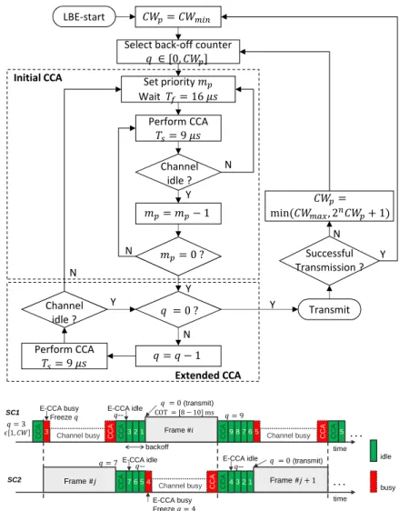
In the case of LBE, a random backoff mechanism relatively similar to the CSMA/CA of WiFi is performed by the SC to get channel access, promising fair access solution. This channel access scheme has been retained for the LAA procedure in 3GPP specifications [18] since it allows better coexistence with WiFi system. The channel access procedure for LBE is shown in Figure 7.
! ! ! " C C A time Frame time Frame Frame 3 C C A 3 E-CCA busy Freeze E-CCA idle 2 1 (transmit) C C A 7 6 5 4 C C A 4 3 2 1 -- Channel busy busy idle C C A Channel busy E-CCA idle --E-CCA busy Freeze backoff E-CCA idle -- (transmit) C C A C C A 9 8 7 6 5 Channel busy C C A 5 C C A . . . . . . SC1 SC2
The SC performs an initial CCA over mp slot durations of a defer duration Td. If the channel is found
busy during one slot, the SC repeats the initial CCA. Otherwise, the SC shall perform an extended CCA
(E-CCA) check over q consecutive time periods of duration Ts. The counter q is randomly selected in the
interval [0, CW ], where CW is the length of the contention window. If an E-CCA turns out to be negative, i.e. channel is busy, an initial CCA is performed, maintaining the current value of q. Otherwise, the SC decrements the counter q and performs transmission of the superframe during COT when q reaches zero. The contention window is adapted based on the retransmissions. CW is increased if at least 80% of data packets are not acknowledged. Otherwise, the CW is reset to the minimum value. In our design, we have specified different options for this access mode (referred to as access priority classes in 3GPP specifications). Each option governs the values of the initial CCA duration, the maximum size of the contention window and the duration of the superframe (COT), as shown in Table 3.
Table 3: LBE access mode parameters
Access option mp Td[µs] Ts[µs] CWmin CWmax COT [ms]
1 3 16 + 9.mp= 43 9 15 63 [8-10]
2 7 16 + 9.mp= 79 9 15 1023 [8-10]
In this paper, the maximum allowed COT of 10 ms is considered in order to achieve higher throughput for broadband traffic. However, it is straightforward to extend our work using various COT according to traffic requirements. In both channel access schemes (FBE, LBE), ED threshold is an important value that deter-mines the level of sensitivity to declare the existence of ongoing transmissions. For instance, the maximum ED threshold (TH) for CCA is given by: TH = min(−75 dBm/MHz, max(−85 dBm/MHz, −85 dBm/MHz +
(23 − PTx))), where PT x is the small cell maximum transmit power in dBm. The ED threshold can be
therefore raised if the bandwidth becomes wider and/or the transmit power PT x is lowered.
3.4. Link adaptation
Another important function of this MAC layer is the link adaptation. Link adaptation usually relies on adaptive modulation and coding scheme assigned by the small cell based either on CQI feedbacks sent by the UE or on the signal-to-interference-plus-noise ratio (SINR) computed on uplink packets by the SC. The CQI is computed by the UE based on the worst SINR over beacon and downlink data packets, so that a suitable modulation and coding scheme is chosen in such a way that the user throughput is maximized in case of good channel conditions while at the same time the block error rate is not more than 10%. Both wideband and subband reporting of CQI are supported in the system. In wideband CQI reporting, one CQI value based on the effective SINR is reported by the UE over the entire system bandwidth. Whereas in subband reporting, a vector of CQI values is reported based on the received SINR over every sub-band allowing for more selective scheduling. It is worth highlighting here that the selected MCS along with the scheduled RBs determine the amount of data that can be transmitted from upper layer (MAC) to the physical layer, referred to as transport block (TB) size on one slot. TB sizes are therefore computed for each MCS in function of the number of RBs and integrated as LUTs into the system level simulator. 4. System model and assumptions
This section describes system-level simulation scenarios and various parameter settings considered for as-sessing the performance of UNII-MAC design. The main purpose of these simulations is to provide a set of guidelines to select UNII-MAC parameters depending on the context of the operation, whether it pertains to network density, traffic pattern or possible coexistence with other incumbent systems operating in the same unlicensed spectrum.
4.1. Link-to-system level mapping
The evaluation of the whole network behavior is performed using link and system level simulators indepen-dently. As stated in Section 2, Matlab-based link level simulator is used to evaluate the BLER performance of FBMC physical layer techniques of transmission and reception under different propagation conditions. On the other hand, Wsnet [37] is considered for the system level simulator to implement the MAC design and to evaluate the performance of the network in terms of throughput, coverage, radio resource management, etc. The link-to-system level mapping is usually used as the physical layer abstraction model in order to provide a good tradeoff between link accuracy and computational complexity in the system level simulator. It allows to accurately model the behavior of multi-carrier physical layers under different channels and multiple-access interference conditions using various modulation and coding schemes. The objective is to get an effective SINR from the instantaneous SINR values on each sub-band and to efficiently map this single SINR value into a BLER through LUTs of AWGN performance curves presented in Figure 3. Several effective SINR mapping (ESM) methods have been proposed [38]. In this work, mean mutual information ESM (MIESM) is considered since it provides more accuracy than others mapping approaches [39].
4.2. Simulation scenarios
We consider both indoor and outdoor deployment scenarios based on a regular hexagonal grid composed of 3 rings of 37 SCs as shown in Figure 8. In the case of outdoor scenario, the wrap-around technique is considered in order to simulate a very large network [40]. Wrap-around helps in mitigating the issue of imbalanced interference conditions among the cells in the different rings of the network as outer rings would experience less interference than the inner ring. It is obtained by replicating the hexagonal pattern and by placing 6 virtual copies of it around the original network.
27 26 12 13 28 1 2 7 6 5 4 3 21 20 8 9 22 37 35 18 19 33 17 34 32 16 30 14 15 31 29 24 36 23 10 11 25
Figure 8: Example of 3-rings hexagonal grid model
The SCs are placed at the center of the hexagon, serving 10 uniformly distributed UEs associated according to the highest received power. The simulations are carried out in a non-fading channel, using an extension of the indoor hotspot (InH) and urban micro (UMi) models [41], with spatial correlation of shadowing and line-of-sight/non-line-of-sight (LOS/NLOS) link [40]. This correlation is meant to bring a more realistic network behavior since 2 nodes close one to the other should have a link to the SC with an identical LOS/NLOS probability. Several inter-site distances (ISDs) are considered to evaluate the performance of MAC design in different degrees of network densification and different ED thresholds ranging from -62 dBm to -82 dBm are considered to evaluate the impact of the CCA sensitivity with respect to densification.
The impact of co-channel and adjacent channel interference on the system performance is investigated using the same frequency channel and a frequency reuse factor of 3. In the former case, the interference between
SCs and UEs is explicitly modeled through considering all interferer signals received from simultaneous emissions in neighboring cells. In the latter case, three adjacent channel frequencies are used with a regular pattern. In this case, the interference between adjacent channels is modeled using out-of-band emission masks which are determined by the PSD of multi-carrier signals for the considered underlying PHYs, e.g. FBMC and OFDM. For FBMC with K = 4, no out-of-band emission is assumed. In case of OFDM and FBMC with K = 2, the interference level on an adjacent channel is assumed to be equal to -37 dBc and -44 dBc for 20 MHz bandwidth, respectively. The main simulation parameters are listed in Table 4.
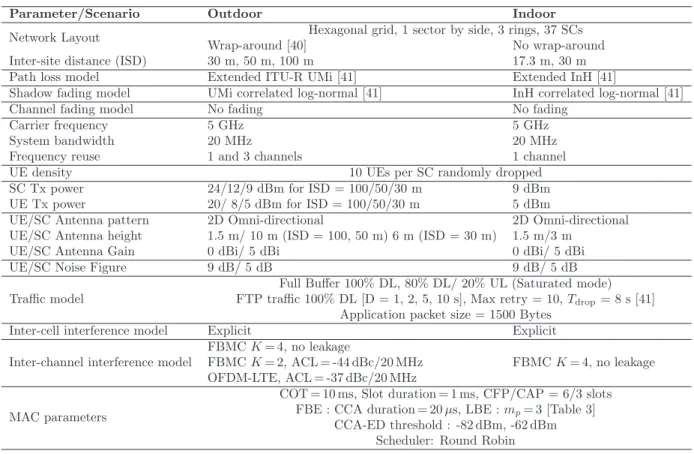
Table 4: Simulation parameters
Parameter/Scenario Outdoor Indoor
Network Layout Hexagonal grid, 1 sector by side, 3 rings, 37 SCs
Wrap-around [40] No wrap-around
Inter-site distance (ISD) 30 m, 50 m, 100 m 17.3 m, 30 m
Path loss model Extended ITU-R UMi [41] Extended InH [41]
Shadow fading model UMi correlated log-normal [41] InH correlated log-normal [41]
Channel fading model No fading No fading
Carrier frequency 5 GHz 5 GHz
System bandwidth 20 MHz 20 MHz
Frequency reuse 1 and 3 channels 1 channel
UE density 10 UEs per SC randomly dropped
SC Tx power 24/12/9 dBm for ISD = 100/50/30 m 9 dBm
UE Tx power 20/ 8/5 dBm for ISD = 100/50/30 m 5 dBm
UE/SC Antenna pattern 2D Omni-directional 2D Omni-directional
UE/SC Antenna height 1.5 m/ 10 m (ISD = 100, 50 m) 6 m (ISD = 30 m) 1.5 m/3 m
UE/SC Antenna Gain 0 dBi/ 5 dBi 0 dBi/ 5 dBi
UE/SC Noise Figure 9 dB/ 5 dB 9 dB/ 5 dB
Traffic model
Full Buffer 100% DL, 80% DL/ 20% UL (Saturated mode)
FTP traffic 100% DL [D = 1, 2, 5, 10 s], Max retry = 10, Tdrop= 8 s [41]
Application packet size = 1500 Bytes
Inter-cell interference model Explicit Explicit
Inter-channel interference model
FBMC K = 4, no leakage
FBMC K = 2, ACL = -44 dBc/20 MHz FBMC K = 4, no leakage
OFDM-LTE, ACL = -37 dBc/20 MHz MAC parameters
COT = 10 ms, Slot duration = 1 ms, CFP/CAP = 6/3 slots
FBE : CCA duration = 20 µs, LBE : mp= 3 [Table 3]
CCA-ED threshold : -82 dBm, -62 dBm Scheduler: Round Robin
In addition, non-coexistence and coexistence scenarios are investigated. In the non-coexistence scenario, we evaluate the performance of UNII-MAC design when it operates without any other interfering system. In the coexistence scenario, FBMC system (operator A) is deployed alongside with a WiFi system (operator B), both using the same 20 MHz channel. In this case, we assume that WiFi APs are randomly dropped in the area with several AP/SC densities. WiFi uses standard distributed coordination function (DCF) CSMA/CA (without RTS/CTS signaling) with an exponential backoff mechanism and transmission duration of 5 ms. The main aim of this scenario is to ensure fair coexistence with other incumbent systems operating in the same unlicensed spectrum. In another word, UNII-MAC design should not impact WiFi systems more than an additional WiFi network on the same channel.
4.3. Traffic model
In terms of traffic patterns, 100% downlink traffic and 20% uplink/80% downlink traffic are considered. In this latter case, the assumption is made that 20% and 80% of the nodes in an SC have only uplink and downlink traffic, respectively. Two types of traffic are considered, namely full buffer and bursty traffic. Full buffer traffic allows investigating the network behavior under saturated conditions where nodes always have a packet in their transmission queue. For bursty traffic, FTP traffic model is considered [41]. This type of
traffic model reflects variable traffic density and time-varying interference level. The simulations are run for various file inter-arrival times D (referred to as reading time), which corresponds to the time interval between the end of the download of the previous file and the user request for the next one.
4.4. Performance metrics
The key performance metrics considered in the evaluation are as follows: UE throughput, UE transmission delay, SC throughput, fairness and channel occupancy statistics. For full buffer situation, the UE throughput is defined as the ratio of the number of correctly received bits over the given simulation time. In the case of bursty traffic (FTP traffic), the UE throughput is obtained by averaging the throughput obtained when downloading different files. The SC throughput is also considered to evaluate the total capacity of the small cell; it is obtained by averaging for all the SCs the correctly received data with respect to the simulation duration. The transmission delay is the averaged time required to successfully deliver a packet once it is at the head of the MAC queue. Fairness metric is used to determine whether users or applications are receiving a fair share of system resources. The fairness of channel access, user throughput, and cell throughput are measured using a Jain’s fairness index. Meanwhile, the mean channel occupancy is defined as the average of the total transmission time of SCs or WiFi APs over the simulation time. This metric is considered to evaluate the fairness of coexistence between UNII-MAC and WiFi systems.
5. Simulation results
In this section, we present simulation results of the proposed UNII-MAC design following the assumptions defined in Section 4. Note that the performance of UNII-MAC design has been compared with a WiFi system under full buffer traffic in the outdoor deployment scenario [42]. It has been shown that UNII-MAC outperforms the WiFi system, and improves the performance by more than 50% in terms of area spectral efficiency, especially for cell-edge users. Herein, the performance of UNII-MAC design is first investigated in the non-coexistence scenario and then in the coexistence scenario.
5.1. Non-coexistence scenario
In the non-coexistence scenario, we first investigate the impact of both channel access mechanisms (FBE, LBE) on the system performance. Next, the benefits of using FBMC physical layer are illustrated by considering OFDM and FBMC waveforms using a frequency reuse scheme. The impact of changing ED thresholds is also analyzed, followed by investigations of the impact of traffic load under different mean reading times of FTP traffic. In all cases, the simulations are conducted for various ISDs in indoor/outdoor scenarios.
Impact of channel access mechanisms (FBE, LBE)
Figure 9 shows the Jain’s fairness index of channel access for FBE and LBE channel access mechanisms under full buffer (left) and FTP traffic with D = 5 s (right). It can be seen that in the case of full buffer, FBE access mode blocks the activity of most SCs. For instance, with ISD = 30 m and ED = -82 dBm, a worst channel access fairness of 0.1 is achieved, meaning that only 10% of SCs are able to transmit while other SCs (90%) are blocked. Even though the ISD is increased to 100 m and the ED threshold is increased to -62 dBm, the percentage of blocked SCs remains significant (roughly 60%). This is mainly due to the fixed frame period of FBE as discussed in Section 3.3. In the case of bursty traffic (FTP D = 5 s), FBE channel access fairness increases significantly compared to the full buffer case. This is caused by the reduction of the traffic load in the system that allows more SCs to get access. However, LBE achieves better fairness between SCs due to the random backoff procedure, e.g. the fairness of channel access ≥ 0.8 in all cases. Figure 10 presents the achieved SC throughput vs. ED thresholds and ISDs for FBE and LBE channel access mechanisms. The results show that increasing the ED threshold increases the transmit opportunities for both channel access schemes (FBE, LBE), and achieves higher SC throughput. Moreover, in the case of full buffer, FBE achieves SC throughput performance comparable to LBE in spite of the SC blocking phenomenon. This can be explicated by the higher throughput achieved by served UEs as depicted in
Figure 11 that shows the cumulative density functions (CDFs) of UE throughput. Indeed, UEs associated with the transmitting SCs experience a good SINR and achieve high throughput. However, in the case of LBE, SCs perform a random backoff procedure and may defer more frequently when other SCs are active. This results in increasing the transmission delay and reducing the UE throughput compared to FBE at the expense of a good fairness access. It is worth noting also that in the case of FTP traffic, FBE presents a low percentage of outage user (≺ 5%) and a high served UE throughput.
!"# # $ % !"# # $ % "# # $ % "# # $ %
&' $
Figure 9: Jain’s fairness index of channel access for FBE and LBE, Full buffer (left), FTP D = 5 s (right), 100%DL
!"# # $ % !"# # $ % "# # $ % "# # $ %
&' $
Figure 10: SC throughput vs. ISDs and ED thresholds for FBE and LBE, Full buffer (left), FTP D = 5 s (right), 100%DL
0 1 2 3 4 5 6 0 0.1 0.2 0.3 0.4 0.5 0.6 0.7 0.8 0.9 1 CDF DL UE Throughput [Mbps] Full Buffer ISD = 30 m ISD = 50 m ISD = 100 m FBE LBE high percentage of blocked SCs in FBE high served UE throughput in FBE 0 10 20 30 40 50 0 0.1 0.2 0.3 0.4 0.5 0.6 0.7 0.8 0.9 1 CDF DL UE Throughput [Mbps] FTP D = 5 s ISD = 30 m ISD = 50 m ISD = 100 m 0 0.5 1 0 0.05 0.1 Percentage of blocked SCs in FBE is reduced FBE LBE
Figure 11: CDFs of UE throughput for FBE and LBE, ED = -62 dBm, Full buffer (left), FTP D = 5 s (right), 100%DL
We can see from these results that different trade-offs can be obtained in terms of fairness and UE throughput depending on the selected channel access mechanisms. FBE approach may be suitable for non-crowded
situations since it allows to substantially maximize UE throughput with a simple channel access. Provided that coexistence with other systems is a key feature for a MAC designed to operate on a shared channel, LBE approach is considered for further investigation on system performance in the following sections. Impact of PHY layer
In this section, we study the impact of adjacent channel interference caused by the PHY waveform on the system performance. FBMC modulation with an overlapping factor of 2 (K = 2) and OFDM-based modula-tion are investigated. A frequency reuse factor of 3 is considered, where adjacent SCs are assigned different 20 MHz unlicensed channels. Figure 12 shows the CDFs of UE throughput and UE transmission delay, given different PHYs. It can be seen that FBMC with K = 4 achieves high throughput performance compared to OFDM and FBMC with K = 2, especially for cell-edge UEs. For instance, the average UE through-put improvement of FBMC with K = 4 compared to OFDM is about 8%, 14% and 13% with ISD = 30, 50 and 100 m, respectively. This is mainly due to the spectrum confinement of well-designed FBMC filter (K = 4). Meanwhile, in the case of OFDM and FBMC with K = 2, the highest level of out-of-band emission leads to an increase of the interference which affects the channel quality, leading to a decrease in terms of UE throughput. It is worth noting that, in the case of ISD = 100 m, the curves tend to reach a saturation throughput since the majority of UEs experience good channel conditions, and are assigned the higher MCS. In addition, the results reveal no significant effect on the UE transmission delay since the traffic load in the system has not been changed, regardless of adjacent channel leakages. These results justify the use of FBMC modulation with a larger overlapping factor.
0 1 2 3 4 5 6 0 0.1 0.2 0.3 0.4 0.5 0.6 0.7 0.8 0.9 1 CDF DL UE Throughput [Mbps] FBMC K = 4 FBMC K = 2 OFDM 30 m 50 m 100 m 0 5 10 15 20 25 30 0 0.1 0.2 0.3 0.4 0.5 0.6 0.7 0.8 0.9 1 CDF DL UE delay [ms] 100 m 50 m 30 m FBMC K = 4 FBMC K = 2 OFDM
Figure 12: CDFs of UE throughput (left) and transmission delay (right) using different PHYs (FBMC K = 4, 2, OFDM), ED = -62 dBm, Frequency reuse 3
Impact of CCA-ED threshold
In the following, we investigate the impact of ED threshold on the system performance for both indoor and outdoor scenarios using 100%DL full buffer traffic. Figure 13 shows the CDFs of UE throughput and UE transmission delay of UNII-MAC, given different ISDs and ED thresholds. The case where all SCs transmit without performing LBT is also considered as a worst case interference scenario. The results show that lowering the ED threshold to -82 dBm leads to a decrease in UE throughput regardless the reduction of interference level. This stems from the decrease in channel access opportunities of SCs that results in decreasing the offered load on the system. More interestingly, when no LBT is performed, a higher throughput is achieved at the expense of cell-edge UEs, where a small fraction of UEs experiences outage (zero throughput). The reason for this outage is the higher level of interference and collision probabilities coming from the overall activity of cells, especially for dense scenario (ISD = 30 m). However, it is worth
noting that with the increase of ED, the throughput improvement is mainly due to the link adaptation mechanism. The SC assigns a suitable MCS to UEs depending on the channel quality and the level of interference as shown in Figure 14. The results presented in this figure show that higher MCSs (12-15) are assigned in the case of ED = -82 dBm, medium MCSs (6-9) for ED = -62 dBm and low MCSs (3-6) where there is no LBT. This is to be expected as the higher ED threshold results in more interference which in turn affects the channel quality leading to the use of lower MCSs. It can be also observed that in case of dense scenarios (ISD = 30 m), the percentage of lower MCSs is greater compared to ISD = 100 m, due to the higher level of interference. Regarding UE transmission delay, the results in Figure 13 (right) indicate that UE delay decreases with the increase in the ISD and the increase in ED thresholds. This is obviously due to the reduction of the level of interference in the former case and to the increase of the channel access opportunities in the latter case.
0 1 2 3 4 5 6 0 0.1 0.2 0.3 0.4 0.5 0.6 0.7 0.8 0.9 1 CDF DL UE Throughput [Mbps] 0 0.1 0.2 0 0.05 0.1 100 m 30 m ED = −62 dBm ED = −82 dBm Without LBT 0 10 20 30 40 50 60 0 0.1 0.2 0.3 0.4 0.5 0.6 0.7 0.8 0.9 1 CDF UE Average Delay [ms] 100 m 30 m ED = −82 dBm ED = −62 dBm Without LBT
Figure 13: CDFs of UE throughput (left) and transmission delay (right), Full buffer 100% DL, outdoor scenario
!"# $% & ' "( $% & ' "( ) % & ( !"# $% & ' "( $% & ' "( ) % & (
Figure 14: Modulation and coding schemes (MCS) with various ED thresholds, Full buffer 100% DL, outdoor scenario
The impact of ED threshold is also investigated in the indoor scenario with a higher density of SCs as shown in Figure 15. When LBT is not performed, the effect of outage UE is more visible due to the higher level of interference between the SCs in denser scenarios. The impact of lowering the ED on the UE throughput is slightly different. The results show that lowering ED threshold improves the performance of cell-edge UEs. UE transmission delay shows similar trends as in the case of the outdoor scenario presented earlier, where the delay is reduced by increasing ISD and ED threshold.
Impact of traffic load
In the following, we focus on the system performance when FTP traffic model is considered using several file reading times. Figure 16 shows the CDFs of UE throughput and UE average delay in the case of ISD = 30 m and 100 m. The curves for the full buffer case are also plotted as a baseline for the saturated model.
0 0.5 1 1.5 0 0.1 0.2 0.3 0.4 0.5 0.6 0.7 0.8 0.9 1 CDF DL UE Throughput [Mbps] ISD = 30 m ISD = 17.3 m 0 0.1 0.2 0 0.1 0.2 Without LBT ED = −62 dBm ED = −82 dBm 0 10 20 30 40 50 60 0 0.1 0.2 0.3 0.4 0.5 0.6 0.7 0.8 0.9 1 CDF UE Average Delay [ms] ISD = 30 m ISD = 17.3 m Without LBT ED = −62 dBm ED = −82 dBm
Figure 15: CDFs of UE throughput (left) and transmission delay (right), Full buffer 100% DL, indoor scenario
0 10 20 30 40 50 60 0 0.1 0.2 0.3 0.4 0.5 0.6 0.7 0.8 0.9 1 CDF DL UE Throughput [Mbps] D = 1 sec D = 2 sec D = 5 sec D = 10 sec Full Buffer 0 2 4 6 8 0 0.05 0.1 0.15 0.2 ISD = 100 m 0 5 10 15 20 25 0 0.1 0.2 0.3 0.4 0.5 0.6 0.7 0.8 0.9 1 CDF UE Average Delay [ms] D = 1 sec D = 2 sec D = 5 sec D = 10 sec Full Buffer ISD = 100 m 0 5 10 15 20 0 0.1 0.2 0.3 0.4 0.5 0.6 0.7 0.8 0.9 1 CDF DL UE Throughput [Mbps] D = 1 sec D = 2 sec D = 5 sec D = 10 sec Full Buffer 0 0.5 1 1.5 2 0 0.025 0.05 0.075 0.1 ISD = 30 m 0 10 20 30 40 0 0.1 0.2 0.3 0.4 0.5 0.6 0.7 0.8 0.9 1 CDF UE Average Delay [ms] D = 1 sec D = 2 sec D = 5 sec D = 10 sec Full buffer ISD = 30 m
Figure 16: CDFs of UE throughput (left) and transmission delay (right), ED = -62 dBm, FTP traffic 100% DL, outdoor scenario
The results indicate that lowering the mean file inter-arrival time D results in reducing the UE throughput and increasing the delay as expected due to the increase of traffic load, especially for cell-edge UEs. As opposed to full buffer, in bursty traffic, the number of served UEs is varying over time, depending on file reading time. It may happen that only one UE is active at a time, for instance. In this case, the served UE is able to download FTP file in a very small time duration leading to a high achieved throughput up to 60 Mbps. Reducing mean reading time increases the number of active users at a time, which leads to increasing the channel occupancy of SCs. This increase of channel occupancy produces more contention and increases the probability of SCs to defer more frequently, resulting in lower achieved throughput. With D = 1 s, the traffic density increases significantly and presents UE throughput performance comparable to full buffer traffic especially in the case of ISD = 30 m. As for the delay, the results present even a higher delay compared to full buffer due to the packet retransmission.
Figure 17 and Figure 18 summarizes the average cell throughput and the average UE throughput for different mean reading times and ISDs in outdoor and indoor scenarios, respectively. The results indicate that traffic load has a huge impact on the overall system performance for both scenarios. Indeed, the SC throughput decreases with the increase of mean reading time due to the decrease of the offered load on the system. Meanwhile, UE throughput is increased and the transmission delay is reduced due to sporadic traffic aspects, e.g. not all UEs are active at a time. Similarly to full buffer traffic, increasing ISD improves the system performance since the level of interference is lower.
0 5 10 15 20 25 0 2 4 6 8 10 12 14 0 1 2 3 4 5 6 7 8 9 10 U E t h ro u g h p u t [M b p s ] S C t h ro u g h p u t [M b p s ]
Mean reading time D [sec] ISD = 30 m ISD = 50 m ISD = 100 m SC throughput UE throughput Full Buffer 0 2 4 6 8 10 12 14 0 1 2 3 4 5 6 7 8 9 10 M e a n D e la y [ m s ]
Mean reading time D [sec]
ISD = 30 m ISD = 50 m ISD = 100 m
Full Buffer
Figure 17: Average SC/UE throughput (left) and UE transmission delay (right), FTP 100% DL, outdoor scenario
0 0,5 1 1,5 2 2,5 3 0 0,5 1 1,5 2 2,5 3 3,5 4 0 1 2 3 4 5 6 7 8 9 10 U E t h ro u g h p u t [M b p s ] S C t h ro u g h p u t [M b p s ]
Mean reading time D [sec] ISD = 30 m ISD = 17.3 m SC throughput UE throughput Full Buffer 0 2 4 6 8 10 12 14 16 18 0 1 2 3 4 5 6 7 8 9 10 M e a n L a te n c y [ m s ]
Mean reading time D [sec] ISD = 30 m ISD = 17.3 m
Full Buffer
Figure 18: Average SC/UE throughput (left) and UE transmission delay (right), FTP 100% DL, indoor scenario
Impact of uplink traffic
In the following, we investigate the system performance when uplink traffic is considered, assuming the full buffer traffic model. The main aim here is to evaluate the performance of UEs transmitting in the uplink.
Figure 19 shows DL/UL UE throughput and delay performances. It can be seen that UL throughput of cell center UE is higher compared to DL throughput especially in the case of ISD = 100. This is due to the reduced number of UL UEs compared to DL UEs scheduled in a slot. Indeed, in this DL/UL scenario, we assume that 2 UEs are uplink users, while 8 UEs are downlink users. Consequently, the total bandwidth will be shared by 8 UEs in DL and 2 UEs in UL resulting in higher resource allocations for UL users and therefore higher throughput. However, the UL performance of cell-edge UEs is significantly lower than DL performance. This relates to a significantly higher level of interference in the uplink direction that results in lower SINR. In addition, UL transmission experiences higher mean transmission delay compared to DL transmission. This is because the number of resource blocks scheduled for UL (2 slots) is smaller than for DL (4 slots). Compared to full buffer 100% DL, we notice that the results for the DL traffic UEs are consistent with the previous results. One of the interesting aspects is that DL throughput is proportional to the number of scheduled slots and the number of scheduled users, as expected.
0 1 2 3 4 5 6 0 0.1 0.2 0.3 0.4 0.5 0.6 0.7 0.8 0.9 1 CDF DL/UL UE Throughput [Mbps] 0 0.1 0.2 0.3 0.4 0.5 0 0.05 0.1 0.15 0.2 UL DL 30 m 50 m 100 m 0 10 20 30 40 50 60 0 0.1 0.2 0.3 0.4 0.5 0.6 0.7 0.8 0.9 1 CDF
UE DL/UL Average Delay [ms]
ISD = 30 m ISD = 50 m ISD = 100 m
UL DL
Figure 19: CDFs of DL/UL UE throughput (left) and transmission delay (right), Full buffer 80% DL/ 20% UL, outdoor scenario
5.2. Coexistence scenario
In this section, we analyze the coexistence of UNII-MAC and WiFi networks using the same 20 MHz channel. The main purpose of this scenario is to evaluate the impact of WiFi system on UNII-MAC performance and to determine the fairness of coexistence by comparing the mean channel occupancy of both systems. This study is restricted to outdoor deployment under full buffer traffic model with 100%DL, which is considered as a worst-case scenario.
Figure 20 shows the impact of WiFi system on the average SC throughput and mean channel occupancy of UNII-MAC system, considering several APs densities. The zero density corresponds to the non-coexistence scenario, i.e. only UNII-MAC SCs. Due to the shared channel nature and the existence of additional interference caused by WiFi system, we observe that increasing the APs density results in reducing SC throughput performance and the mean channel occupancy of UNII-MAC compared to the non-coexistence scenario. The presented results show also that lowering ED threshold to -82 dBm improves SC throughput, especially for cell-edge UEs. Indeed, using an ED threshold of -62 dBm for both systems may result in severe interference and collision and degrade significantly the throughput performance of UNII-MAC system. In Figure 21 (left), the mean channel occupancy of WiFi and UNII-MAC systems are presented assuming one AP per SC (i.e. AP/SC density = 1). The results reveal that using same ED threshold allows fair channel occupancy between both systems. We show also that lowering ED threshold to -82 dBm reduces the mean channel occupancy of both systems and achieves better UNII-MAC performance as presented in Figure 20. It is worth highlighting here that using asymmetrical ED threshold improves the performance of one system at the expense of the other system whose activity is almost negligible.
Moreover, we have investigated the impact of UNII-MAC (operator A) on the performance of WiFi (opera-tor B) by comparing with a scenario where both opera(opera-tors deploy WiFi (i.e., UNII-MAC SCs are replaced by WiFi APs) as shown in Figure 21 (right). In the WiFi-WiFi scenario, we observe that the mean channel occupancy of operator B is similar if operator A deploys either WiFi or UNII-MAC systems. From the ob-tained results it can be clearly seen that ED threshold has a significant impact on both UNII-MAC and WiFi system performances. The setting of the ED parameter can be then used to trade-off performance between coexisting systems. This indicates that the LBT feature of UNII-MAC is an efficient mechanism to provide fair coexistence with other systems operating in the same band, without causing significant performance degradation. !" # $ %& !" # $ %& ' ( ) (( ( * + , !" # $ %& !" # $ %&
Figure 20: Average SC throughput for UNII-MAC (left) and mean channel occupancy of SC (right)
! " # # ! $%"% &'( ) &'( ) ! "#$# ! "#$# %&' ( %&' (
Figure 21: Mean channel occupancy of UNII-MAC and WiFi (left) and WiFi-WiFi systems (right)
We have presented in this section the performance of UNII-MAC for a range of scenarios, traffic mod-els, and PHY/MAC specific parameters. Based on the simulation results, the following conclusions and recommendations are drawn:
• LBE presents better performance in terms of channel access opportunities and achieves better fairness
among SCs than FBE. This is due to the contention process applied by the SCs which avoids the SC blocking phenomenon observed in FBE. However, in low-density traffic and non-crowded spectrum, FBE can be a very interesting solution as it maximizes the channel occupancy and therefore the user throughput.
• PHY layer considerations such as modulation type (FBMC, OFDM) and FBMC filter design may
significantly affect the performance due to out-of-band leakages of OFDM and non-well design filter. This is particularly visible using a frequency reuse factor of 3, where adjacent small cells are assigned
different frequency channels. The results confirm that FBMC outperforms OFDM waveform, providing a gain of almost 15% in terms of cell throughput for small ISDs.
• Traffic density has a decisive impact on the overall system performance. Depending on traffic load
and inter-site distance between cells, ED threshold should be carefully adjusted to allow for a trade-off between performance and good coexistence properties. Interestingly, lowering ED threshold below -62 dBm in saturated mode results in less interference and collision and allows to improve the perfor-mance of cell-edge user with small ISDs. On the other hand, the same low threshold has a negative impact for larger ISDs as it reduces the cell throughput and increases the mean delay. Bursty traffic model results in better UE performance compared to the full buffer, as the traffic load is smaller.
• In UL/DL full buffer scenario, the achieved DL throughput is proportional to the number of scheduled
slots. The number of slots is an important parameter that should be configured depending on the UL/DL traffic load.
• UNII-MAC is capable of coexisting with WiFi systems when operating in a shared band. The
coexis-tence performance depends on traffic types, ED-thresholds and APs density. Fair coexiscoexis-tence requires appropriate tuning of ED thresholds of both systems. Reducing the ED threshold of both systems to -82 dBm improves the performance of cell-edge users compared to ED threshold -62 dBm; both values allow a fair channel occupancy between the two systems provided they use the same ED threshold values.
6. Conclusion
In this paper, UNII-MAC protocol for 5G ultra-dense small cells designed to operate in the 5 GHz unli-censed band has been presented. It is specifically based on a beacon-enabled MAC protocol, assuming an FBMC physical layer. It is worth noting that the proposed design can be generalized with other waveforms having good filtering properties such as BF-OFDM. First, FBMC physical layer parameters have been de-fined. In particular, the time-frequency localization features of FBMC is exploited in order to maximize spectrum utilization thanks to the extremely low out-of-band emission and to facilitate resource allocation and asynchronous channel access in the uplink. Next, the MAC protocol based on the beacon-enabled su-perframe has been described. The susu-perframe structure mixes both scheduled-based and contention-based access schemes. The superframe transmission is triggered by an LBT procedure in order to comply with the ETSI requirements and to coexist with neighboring systems sharing the same band. The LBT channel access modes, namely FBE and LBE, have been then discussed. Furthermore, the performance of UNII-MAC system in case of non-coexistence and coexistence scenarios has been evaluated under various network densities, PHY/MAC related parameters, LBT sensitivities and traffic patterns. Performance results, as well as coexistence results, are reported showing that UNII-MAC is able of operating effectively in highly dense deployment scenarios and able of providing fair coexistence with WiFi systems through tuning the ED thresholds. The results show also that the FBMC waveform using well-designed filter shows promising features for dense networks when high-frequency reuse patterns are used. Indeed the very low out-of-band leakage level of FBMC helps reduce the interference injected in adjacent channels and outperforms CP-OFDM systems. Another important aspect is that the superframe structure can be adapted to support various uplink and downlink broadband wireless access in ultra-dense deployments.
Acknowledgments
The research leading to these results received funding from the European Commission H2020 program under grant agreement no. 671705 (SPEED-5G project).
Competing interests