Design of Nanomanufacturing Systems by
Alexander H. Slocum, Jr. S.B. Mechanical Engineering
Massachusetts Institute of Technology, 2008
Submitted to the Department of Mechanical Engineering in Partial Fulfillment of the Requirements for the Degree of
Master of Science in Mechanical Engineering at the
Massachusetts Institute of Technology June 2010
ARCHIVES
MASSACHUSETTS INSTITUTE OF TECHNOLOGYSEP 0
1
2010
LIBRARIESi
© 2010 Massachusetts Institute of Technology All rights reserved.
Signature of Author... ... H. Slocum, Jr. Myth Z OO, ~May 7h ,2010 C ertified b.. .- - ---Martin L. Culpepper Associate Professor of Mechanical Engineering
7 "/ Thesis Supervisor
1~, ~ // Accepted by... .....
David E. Hardt Professor of Mechanical Engineering Graduate Officer
Design of Nanomanufacturing Systems by
Alexander H. Slocum, Jr.
Submitted to the Department of Mechanical Engineering on May 7th, 2010 in Partial Fulfillment of the Requirements for the Degree of Master of Science in
Mechanical Engineering
ABSTRACT
Thesis Supervisor: Martin L. Culpepper
Title: Associate Professor of Mechanical Engineering
Over 100 years of manufacturing knowledge and experience are available to a design engineer when considering the integration of a machine tool enabling macro-scale processes (milling, turning, welding, water-jet cutting) into a production or manufacturing line, and this thesis seeks to provide a design engineer with the insight so that the same can be done for a nano-scale process such as Dip Pen Nanolithography and Nanoimprint Lithography. Accordingly this work presents methods for designing nanomanufacturing systems, including the development of new technology to fulfill the unique performance requirements of nanomanufacturing processes. First, an introduction to nanomanufacturing and the differences between macro-scale and nano-scale manufacturing will be presented. Second, a "metric mapping" method will be illustrated which can be used to identify areas of nano-manufacturing where the need for the development of new technology is critical. Thirdly, this new method is capable of helping a design engineer synthesize technology for nano-manufacturing, as will be shown through a case-study in which a modular, precision belt-drive machine which is capable of enabling throughput nanomanufacturing was designed and built. This machine for high-rate nanomanufacturing not only exceeds the performance requirements for a process (Dip Pen Nanolithography, or DPN) that has been called "not suitable for high-rate nanomanufacturing", but also is capable of implementing DPN at a rate almost 200 times that of previous machines.
ACKNOWLEDGEMENTS
First and foremost I would like to thank my family; your tough love, support, and guidance, SCUBA Diving, Snowbaording, trips to Iceland, Colorado, Australia, New Zealand, Japan, France, Mexico, Canada, Alaska, Hawaii, the list goes on; you guys are the best and I love you!
Sarah; you keep me sane (which is a full-time job); you are an incredible woman, thank you for the patience and laughs, breakfast, and helping to edit this thesis. I love you.
Martin Culpepper; my advisor, mentor, and friend. I remember our first soccer game, that was a blast. I have learned so much from you, whether I wanted to or not; thank you for your guidance (and patience) over the past two years. I am honored to have had the opportunity to work with you these past two years.
Christopher DiBiasio; we worked together on big parts of this project. Chris refined and perfected the use of the HexFlex nano-positioner so that it could be easily integrated into the machine. We also spent a lot of time talking about nanomanufacturing and Chris also helped with the design process and was present as a majority of the design reviews. Go Red Sox!
Sourabh Saha; without Sourabh, chapter 2 would have taken a lot longer than it did. He laid the groundwork for many aspects of the chapter in a paper the lab wrote in the summer of 2009, and also helped me to refine the metric mapping method presented in this thesis.
Robert Panas and Michael Cullinan; It was always nice to be able to bounce ideas off of two brilliant dudes and get great suggestions back. Bob, I also enjoyed all those runs around the Charles River, great for clearing the mind. Have fun in California!
Bill Buckley; Bill was awesome and a great help; he re-worked some parts for me for the first iteration of the nanomfg machine.
Eric Hobbs at FormFactor, Inc.; Eric and I met at the 2009 ASPE conference. He had a LOT of great ideas with regards to the fledgling design that I had just presented at the conference. The questions he posed, such as how does one de-couple the coarse belt-motion from the precision motion required to position the sample, helped me to identify design opportunities that in the end proved key to the machine's overall function.
Reuven Schmerling and Belt Technologies in Agawam, MA; Ruby took what was a 7-week lead time and somehow welded up an awesome stainless steel belt in two weeks. They are the masters of precision belt fabrication and theirs is truly an impressive piece of work.
Annie Ye at Pooward Precision Machinery Manufacture in Guangdong, China; Very high quality precision manufacturing establishment, very friendly, and definitely exceeded my expectations. They produced a majority of the components for the belt drive and material handling systems.
Charles Cummings, Ed Warnock, and Bill Zioli at Hillside Engineering in Danvers, MA; Bill
drove to my lab to pick up a part for re-work on extremely short notice. Chuck and Ed do an
absolutely fantastic job running the shop, and all three are very professional, well-organized, and the precision manufacturing work produced by Hillside is very impressive; they did the re-work of the original machine frame, the plug for the HexFlex, and the mount for the belt-drive motor.
Joe Martino, Janet Galipeau, and Patel Biren at Maxon Motor USA; Friendly, professional, top-notch customer service. Joe and Janet helped me procure the right motor for my application, and Patel directed me to .DLL files and very helpful sample VIs while I was trying to get the motor to run using LabView.
Roger Lemire at HaydonKerk Motion Solutions helped me figure out the correct part numbers for the non-captive linear motor used to actuate the proof-of-concept belt drive machine, and also the air bearing linear motor.
I also owe a special thank you to Rob Mazzarese and Charles Slade; while talking about patent claims and deadlines, they helped me for 3+ hours to assemble the various components of the machine as part of our "IP meeting", the result of which can be seen in Figure 4.31.
CONTENTS
A bstract ... .. ---... 3 Acknowledgements... ...-- - - - 4 C ontents ...---...--- -- -- 7 Listing of Figures...- . ---... 11 Listing of Tables ... . ---... ---... 15 Chapter 1... ... ---... 16 1.1 Manufacturing Systems ... 18 1.1.1 Why Manufacturing? ... ... ... ... . . . 19 1.2 Manufacturing System... ... 20 1.2.1 Flow Shop ... - ... 21 1.2.2 Job Shop ...---... 22 1.2.3 Machining Cell... 231.2.4 Manufacturing Equipment and Machine Tools ... 24
1.3 M anufacturing Processes ... 25
1.3.1 M anufacturing V ariables ... 26
1.4 Nanomanufacturing Systems ... 28
1.4.1 Nanomanufacturing Processes ... 30
1.4.2 Nanomanufacturing Variables ... 30
1.4.3 Metric Mapping for Conventional Processes... 31
1.4.4 Instruments for Nanomanufacturing ... 32
1.4.5 Nanomanufacturing Equipment ... 35 1.5 Scope... ... . ... 36 C hapter 2 ...-.. ---... 38 2.1 Opportunities in Nanomanufacturing ... 38 2.1.1 R ate ... . -... ---... 39 2.1.2 C ost ... . ---... 40 7
2.1.3 Quality...40
2.1.4 Flexibility...41
2.1.5 Low cost equipm ent... 41
2.2 Classification of N anom anufacturing Processes... 43
2.3 N anom anufacturing processes ... 47
2.4 2-D N anom anufacturing Processes... 47
2.4.1 Scanning-based N ano-M fg Processes... 49
2.4.1.1 Dip Pen N anolithography ... 50
2.4.1.2 M icro- and N ano-EDM ... 52
2.4.1.3 EBL and SBL ... 53
2.4.1.4 Scanning Tunneling M icroscopy Lithography ... 54
2.4.2 Tem plate-based N ano-M fg Processes... 55
2.4.2.1 N ano-Im print Lithography ... 55
2.4.2.2 Therm olithography ... 57
2.4.2.3 N ano-Contact Printing ... 58
2.4.3 Scanning-based Vs. Tem plate Based Processes ... 59
2.5 3-D N anom anufacturing Processes... 63
2.6 N anom anufacturing Technology ... 64
2.7 Chapter acknowledgem ents ... 65
Chapter 3... 66
3.1 M etrics for (N ano)-M anufacturing ... 66
3.1.1 H igh-Level M etrics... 67
3.1.2 Low -level m etrics ... 69
3.1.2.1 Rate ... 69
3.1.2.2 Cost ... 70
3.1.2.3 Quality... 70
3.1.2.4 Flexibility... 70
3.2 N anom anufacturing Technology Synthesis ... 70
3.2.1 M etric-M apping ... 71
Chapter 4... 74
4.1 Design Process ... - - - --... 74
4.1.1 Metric Mapping ... 76
4.1.1.1 Process Identification... 77
4.1.1.2 Comparison of High-Level Metrics ... 77
4.1.1.3 Process Physics ... .... 78
4.1.1.4 Comparison of Low-Level Metrics... 78
4.1.2 Rate Analysis Case Study: DPN Linking of DNA ... 79
4.1.3 Analysis of Acceptable Machine Architecture ... 81
4.2 Design of a Nanomanufacturing Machine ... 87
4.2.1 Error Budget... ... ... 91
4.2.2 Machine Functional Requirements ... 93
4.3 Modelling, Fabrication, and Testing... 93
4.3.1 First Generation Nanomanufacturing Machine ... 95
4.3.2 Performance of Flexure-Modified Kinematic Couplings ... 96
4.3.3 Performance of Quasi-Kinematic-Couplings... 97
4.4 Second Generation Nanomanufacturing Machine ... 100
4.4.1 Nano-positioning System... 101
4.4.2 Material handling System ... 102
4.4.3 Material Transport System... 105
4.4.3.1 Perforated Indexing Belt ... 109
4.5 Machine Operation... 111
C h ap ter 5 ... 112
5.1 Technology Development... 112
5.1.1 Improvements to the Current System ... 112
5.1.2 Nanomanufacturing Process Development... 113
5.1.3 The Modular Nanomanufacturing System... 114
5.1.4 Scaling L aw s... 115
5.2 Improvements to the Current Design... 116
5.2.1 Belt Tensioning Mechanism... 116
5.2.2 Pre-load Mechanism ... 116
5.2.3 Design for Continuous Processing... 117 9
5.2.4 Nanomanufacturing Line...118
R eferen ces...121
LISTING OF FIGURES
Figure 1.1: Johns Hopkins Ruling Engine [4]. ... 17
Figure 1.2: Flow shop diagram [9]. ... 22
Figure 1.3: Job shop diagram [9] ... 23
Figure 1.4: M achining cell diagram [10] ... 24
Figure 1.5: Manufacturing systems characterized with respect to rate, quality and flexibility.... 27
Figure 1.6: PUGH chart comparing manufacturing systems to process parameters. ... 31
Figure 1.7: a) NanoInk NScriptorTM DPN@ system [17]; b) Sodick AE05 Nano EDM machine [18]... .. ---... ... 33
Figure 1.8: Belmont Maxicutrm EDM Machine [21]. ... 34
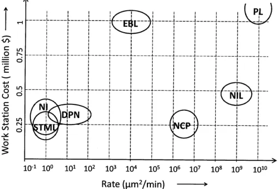
Figure 2.1: Workstation cost vs. area processing rate for Dip Pen (DPN), Scanning tunneling microscopy lithography (STML), indentation (NI), E-beam Lithography (EBL), Nano-Imprint Lithography (NIL), Nanocontact Printing (NCP), and Photolithography (PL) [23]. ... 42
Figure 2.2: Small-scale (micro or nano) machining operations classified in terms of volume and rate vs. m anufacturing system type [24]... 46
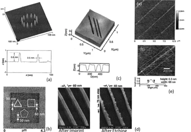
Figure 2.3: Examples of features manufactured using various nanomanufacturing processes: a) Cu deposition via STM [25]; b) Geometric thiol patterning using DPN [26]; c) 5 nm wide lines made using mechanical nano-indentation on GaSb/20nm InAs [27]; d) PMMA lines imprinted with a 75 nm step-over using nano-imprint lithography [28]; and e) Titin multimer protein lines created on the surface of a silicon substrate using nano-contact printing [29]... 49
Figure 2.4: Dip Pen Nanolithography schematic... 51
Figure 2.5: Nano-EDM machine (left) and a 250x250 pm cavity (right), with a central 1 ptm diameter raised cylinder in the center, EDM-ed using Pt-Ir tips. The pocket depth was not given [4 0 ]... 5 2 Figure 2.6: Example of EBL proximity effects (top), and gratings written using SPL (bottom). 54 Figure 2.7: Scanning Tunneling Microscopy Lithography in deposition mode, depositing a copper cluster onto a gold substrate [25] ... 55
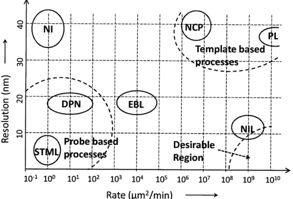
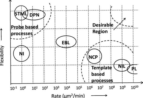
Figure 2.9: Thermolithography schematic diagram showing cross-linking in the polymer coated to the surface of a substrate, resulting in UV resistance and the creation of a pattern upon further exposure to U V . ... 58 Figure 2.10: Nano-contact printing schem atic... 59 Figure 2.11: Resolution versus rate for some common nanomanufacturing processes: Dip Pen (DPN), Scanning tunneling microscopy lithography (STML), Nano-indentation (NI), E-beam Lithography (EBL), Nano-Imprint Lithography (NIL), Nanocontact Printing (NCP), and Photolithography (PL) [23]... 60 Figure 2.12: Flexibility versus rate for some common nanomanufacturing processes: Dip Pen (DPN), Scanning tunneling microscopy lithography (STML), Nano-indentation (NI), E-beam Lithography (EBL), Nano-Imprint Lithography (NIL), Nanocontact Printing (NCP), and Photolithography (PL) [23]... 61 Figure 3.1: The Metric Mapping, or METMAP, process illustrated as a flow chart showing: 1) Identification of candidate processes, 2) Comparison of HLMs, 3) Understanding the physics of the process, 4) Comparison of LLMs, and 5) Identification of the "best [macro-] process" to enable a nanom anufacturing process. ... 73 Figure 4.1: Single-axis alignment (left) and 6-axis alignment (right) critical dimensions. For an AFM tip (single-axis), the Z dimension, or tool offset, is the critical process dimension. For template-based and massively-parallel nano-scale processes, planar alignment (right) means that tool offset (Z) and tip/tilt (X, Y rotation) are critical process dimensions. ... 75
Figure 4.2: D PN Rate Calculation ... 80 Figure 4.3: Modified DPN Rate Calculation to show 30 parallel machines... 80 Figure 4.4: Nanomanufacturing machine concept sketches including: rotary tables, swing-loading machines, vertical-motion stamping machines, and hinged-gantry machines... 81 Figure 4.5: PUGH chart for various machine architectures and production layouts. It should be noted that the second-generation nanomanufacturing machine is a version of the "linear H-frame" design depicted here, which was not selected initially. ... 82 Figure 4.6: H ex-Flex sam ple tray. ... 82 Figure 4.7: (a)Rotary table sizes; (b) a solid model of four "long-type" trays with characteristic dim ension of the tray diam eter. ... 84
Figure 4.8: DPN daily production rate vs. number of trays; cycle times of 5, 6, and 10 seconds
are shown. ...-- - - . 86
Figure 4.9: Proof-of-concept sketch for the belt-drive model, pasted in a design notebook. The dashed line shows the first mention of the term "nano-transfer line" during this project... 87
Figure 4.10: Solid model of the proof-of-concept sketch for the belt-drive nanomanufacturing m achine... . ---... 88
Figure 4.11: Power budget for the proof-of-concept belt-drive machine... 89
Figure 4.12: Proof-of-concept belt-drive machine. This sketch model was useful for highlighting some of the challenges associated with belt-drives, most importantly achieving proper tension in the belt, positioning accuracy, and also identifying the key features which would be considered in the error-budgeting for this m achine. ... 90
Figure 4.13: Isometric cut-away view of the sample and tool fixtures showing opposing kinem atic couplings. ... ... ---... 91
Figure 4.14: Error budget calculation for the nanomanufacturing machine (top). The structural loop is shown in a dashed line in this close-up cross-section of the kinematic coupling interface (bottom )... .. ---... 92
Figure 4.15: The use of a thermo-centric design (c) allows the nanomanufacturing machine to mitigate the effects of thermal errors which commonly effect other machine architectures... 94
Figure 4.16: 3-D section-view model of the first generation nanomanufacturing machine with key features labeled... - .... ---... 95
Figure 4.17: First-generation nanomanufacturing machine... 96
Figure 4.18: Sample-holder flexure-modified kinematic coupling performance. ... 97
Figure 4.19: Material handling plug insert quasi-kinematic coupling performance... 98
Figure 4.20: Module mounting structure quasi-kinematic coupling performance (part 1)... 99
Figure 4.21: Module mounting structure quasi-kinematic coupling performance (part 2)... 99
Figure 4.22: Second generation Nanomanufacturing Machine; isometric view (top) and cut-away view (bottom) show the general layout of the machine's components. ... 100
Figure 4.23: A modular, high-precision, belt-drive machine for enabling high-throughput nano-scale m anufacturing. ... . .... ---... 101
Figure 4.25: Material-handling system deflection calculations (left) and free-body diagram (righ t)... 10 3
Figure 4.26: Material-handling system installed in the nanomanufacturing machine... 104
Figure 4.27: Example of a sample/workpiece, with flexure-modified kinematic couplings... 105
Figure 4.28: Solid model of the material transport system... 106
Figure 4.29: Belt drive m otor power budget... 107
Figure 4.30: Solid model of the motor mount and belt tensioning mechanism... 108
Figure 4.31: Belt-drive system integrated into the nanomanufacturing machine... 109
Figure 4.32: Shim stock attached to nylon sheet via double-sided tape(top left); perforated belt post-waterjet (bottom left); laser-welded perforated nanomanufacturing belt (right)... 110
Figure 5.1: a) Cut-away view of the modified tension mechanism; b) isometric view of the m odified belt-drive plug. ... 116
Figure 5.2: Schematic of a rotary-actuator-driven screw-type mechanism driving the linear stage. The range-of-motion is nearly the full height of the material handling plug... 117
Figure 5.3: Schematic of a nano-transfer line being constructed. 1) The metrology module is being added to the end of the line, consisting of modules for coating, writing, and cleaning. 2) The location of a quasi-kinematic interface/flange is shown by the dashed line. 3) A "belt" is added to the nano-transfer line; this represents the individual belts located internal to each module. 4) The modularity of the transfer line is demonstrated when the metrology module is easily moved up the line to before the writing module... 119
LISTING OF TABLES
Table 1.1: Different types of manufacturing systems... 21
Table 2.1: No two schemes for classifying nanomanufacturing processes are alike, and different processes could be classified differently by each method [23]... 44
Table 3.1: Taxonomic classification of different types of manufacturing processes as described by T odd [[66]]...----..- --... ---... 69
Table 4.1: Identification of macro- and nanomanufacturing process for METMAP. ... 77
Table 4.2: Nanomanufacturing machine functional requirements... 93
CHAPTER
1
INTRODUCTION
The goal of this thesis is to show that high-throughput nanomanufacturing is possible. A high-precision, high-throughput, belt-driven nanomanufacturing machine has been designed, fabricated, and shown to a) enable a nanomanufacturing process and b) achieve the required performance to meet the unique needs of nanomanufacturing. In addition to this machine, a design methodology has been developed (Metric Mapping) to help a design engineer identify areas of nanomanufacturing technology in which the development of new manufacturing technology is critical. In order for the full potential of nanotechnology to be realized, nano-scale products must be mass-produced in a cost-effective and efficient manner. The current state of devices used to enable nanomanufacturing processes in a laboratory setting is evidence of the need to drastically increase throughput and move production from the laboratory to the factory. This is an essential step if the full impact of nano-technology is to be realized by society.
History has shown that in general, either the science behind a manufacturing process leads to the development of new technology to enable it [1], or a new technology is developed which then leads to scientific investigation into developing an understanding of the processes. Computer-Numerical-Controlled milling was first demonstrated in a laboratory at MIT, long before it was integrated into manufacturing lines. This practice (of technology developed to meet a need in manufacturing) does not show any sign of wavering; the development of new nanomanufacturing processes has generally begun with research, and once a nanomanufacturing process has been demonstrated to be feasible in the laboratory, the focus should then ideally shift to turning it into a manufacturing process.
Electro-discharge machining (EDM), abrasive waterjet technology, Computer-Numerically-Controlled Machines, and wafer-steppers used in the manufacture and testing of semi-conductors are but a few of the many examples in which a process was first developed and
perfected, and the design of the machine architecture and supporting technologies came second. Nanomanufacturing is currently at a similar stage: the science behind a process exists and a general understanding of how the process works has been achieved; the technology does not exist, however, which is required to enable that process to mass-produce nano-scale products.
Attempting to deliver a single machine or idea that will satisfy the needs of nanomanufacturing as a whole is not a currently viable solution. The nanomanufacturing industry has not yet matured into the broad, unified entity that is, for example, the automobile manufacturing industry [2, 3]. Furthermore, the current state of nanomanufacturing technology is analogous to that of the ruling engines used to make diffraction gratings before the development of the Johns Hopkins Ruling Engine by John Strong in the 1950s [4], see in Figure 1.1.
Prior to Strong's Ruling Engine, the need for a more accurate and precise method of manufacturing diffraction gratings was needed as the limits of performance of Rowland-type ruling engines were being reached. Henry Rowland, a Professor of Physics at Johns Hopkins in the late 1800s, developed the ruling engine which bears his name. His device, and the diffraction gratings manufactured with it, helped to usher in the field of modem astrophysics.
It should be noted that this thesis does not seek to revolutionize the field of nanomanufacturing in the same way Strong's ruling engine revolutionized the production of diffraction gratings, and in turn astrophysics. It does however, seek to highlight the fact that there are a number of lessons that can be learned from history; taking them into account when designing nanomanufacturing machines can enhance a design engineer's ability to more rapidly enable processes still in the "laboratory" stage. Additionally, history shows that history has demonstrated that history repeats itself (etc.). It would behoove any good engineer, when attempting to design machines to enable nanomanufacturing processes to take advantage of the fact that nanomanufacturing is in it's infancy, with plenty of room to make significant contributions designing the latest and greatest nanomanufacturing machines.
Manufacturing technologies to enable any nanomanufacturing processes on a large scale are absolutely necessary to take full advantage of the impact a process can have on society [5]. "For nanotech products to achieve the broad impacts envisioned, they must be manufactured in market-appropriate quantities in a reliable, repeatable, economical and commercially viable manner" [2, 3]. Furthermore, in keeping with the "historical perspectives" approach to designing and building new nanomanufacturing equipment, a relatively brief account of the history of manufacturing is presented. A consideration of certain technological advancements and their impact on the world is also made; parallels are drawn between the invention of those technologies and what has been developed so far in order to enable nanomanufacturing on a large scale.
1.1
Manufacturing Systems
One of the earliest examples of manufacturing systems came about in the early 1800s, through the work of Captain John H. Hall and his system of interchangeable parts. Hall designed and manufactured 1000 M1819 rifles for the US Army in 1819, using interchangeable parts and precision machined components that were critical to the rifle's performance. Hall's Rifle Works, on Lower Hall Island in the Shenandoah River, was the site of critical contributions to the American system of manufacturing. These included the straight-cutting machine (the forerunner of the modem milling machine), and a workshop that, at the time, "mass-produced" firearms using machines operated by boys, not by skilled craftsmen. Captain Hall's work in the manufacture of firearms laid the foundation for the development of mass production in America.
Henry Ford's realization of the need for "a light, low-priced car..." led to the perfection of its governing principles in the early 2 0th century. Even more important than the development
of mass-production at Ford was the diffusion of those ideas and techniques throughout the industrialized world of the early 1900's. The Ford Production System outlined a method and techniques for mass-producing a specific product (in this case the Model T). Its effectiveness is evident in the fact that the 15,000,000th Model T Ford rolled off of the production line just 15 years after being introduced to the public [6, 7].
What is important to note is that:
1. A historical perspective can be used to make improvements on existing technology and identify areas of developmental need;
2. The development of new technology to perform where existing technology doesn't follows suit;
3. Both 1 and 2 can be utilized to do something that previously couldn't be done (and was originally thought to be impossible).
Take for example the differences between the first M1819 rifles and the latest Model Year 2010 luxury sports car. It is humbling, yet enabling, to know that the luxury sports car owes its very existence to the M1819 rifle. In 1819, an automobile from 2010 would have been alien, achieving things that would have appeared the work of magicians (such as GPS). Knowing that today's most technologically-advanced luxury car could be the M1819 rifle to the nano-technological achievements of the very near future provides sufficient motivation to start developing technology and tools for enabling nanomanufacturing.
It is essential that the reader possess a basic understanding of manufacturing technology. If the reader is a newly-minted engineer, it is suggested that the following be reviewed to ensure a solid understanding of the principles of manufacturing discussed herein. If the reader is a well-oiled practicing engineer, it might still be a good idea to at least skim the following sections for a brief review of manufacturing systems and terminology, and to make sure that those terminologies used in this thesis are in alignment with their own.
1.1.1
Why Manufacturing?
Now, on to the good stuff: what is manufacturing? Why do we need manufacturing? Webster's New-World Dictionary defines the word "manufacture" as: "the making of goods,
especially by machinery on a large scale". On a large scale is critical here, because without
manufacturing technology, there would be no public transportation, there would be no computers and the world as we know it today would be drastically different. Manufacturing is one of the key elements that enabled the industrial revolution, and altered the course of human history.
An organized, efficient, and cost-effective manufacturing process allows for large quantities of product to be made and delivered to the customer with smaller lead times, and at lower cost, than if a more stochastic process was used with no organization present. Plain and simple: if you want to make a lot of something (and sell it at a price that a large number of people can afford) some sort of manufacturing system must be implemented to make it. In order to manufacture nano-products in a cost-effective manner, nanomanufacturing equipment is necessary to meet this need.
A piece of nanomanufacturing equipment is a precision machine. It has been said (regarding precision engineering), that "...precision engineerng is dedicated to the continual pursuit of the next decimal place." From the website of the American Society for Precision Engineering (www.aspe.net), "the field of precision engineering encompasses elements of machine design including but not limited to: controls, dimensional metrology, history of precision engineering, instrument/machine design, nanotechnology, scanning microscopes, and ultra-precision machining". If part of what makes a precision engineer is a keen awareness of the history of the field when designing new machines, it would also make sense for extensions of precision engineering, such as the manufacture of nanotechnology using precision nanomanufacturing machines, to be aware of the history of manufacturing systems as well.
1.2
Manufacturing System
A discussion of manufacturing consists of three main elements: manufacturing systems, manufacturing equipment and/or machine tools, and the manufacturing processes which are enabled by the first two. There are three general classifications of manufacturing systems, with the latter two elements (machines and processes) being far too broad and diverse to address thoroughly in this thesis. These manufacturing systems have evolved over the decades of development of manufacturing technology, and are as follows: the Job Shop (JS), the Flow Shop (FS), and the Machining Cell (MC). These manufacturing architectures are discussed in the
following sections. An example of each process is given, as well as a representative product that is manufactured utilizing that process.
It should be noted that the three classifications of manufacturing systems (job shops, flow shops and machining cells) can be further broken down into 7 different types of manufacturing systems [8], as seen in Table 1.1:
Table 1.1: Different types of manufacturing systems.
Mfg System Type Mfg System Sub-Type
1. Job Shop
2. Batch flow
3. Operator-paced line flow 4. Equipment-paced line flow Machining Cell 5. Flexible manufacturing system
6. Just-in-time (JIT) manufacturing systems (a cornerstone of the Toyota Production System)
7. Continuous-Flow shop
Systems 1 and 7 are easily differentiable from each other and also the other manufacturing systems. Systems 2-6 however, are similar in terms of their characterization with respect to the manufacturing variables of rate, cost, quality, and flexibility. As such, these are lumped into the machining cell classification. Job shops, flow shops, and machining cells are fundamentally different in their operational characteristics and their ability to meet the needs of
certain manufacturing applications.
1.2.1
Flow Shop
A flow shop is generally composed of lines of machinery (manufacturing or assembly lines), dedicated to making or assembling a specific part or parts. The shop can have a main line for assembly, with smaller feeder lines which manufacture the parts, or any other configuration which can be thought of by the reader. A flow shop is relatively rigid in its layout, but can produce parts in high volumes. A diagram of a flow shop can be seen in Figure 1.2.
Figure 1.2: Flow shop diagram [9].
1.2.2
Job Shop
In a job shop, the flow of material through the working area is part-dependent. In a job shop, different types of machine are grouped together (milling machines in one area of the shop, grinding machines in another, etc.). The path each part takes through the shop depends purely on the operations required to machine the features on the part. This makes job shops flexible and able to manufacture lots of different types of parts without significant re-arrangement of machine tools, but also limits a job shop to producing smaller volumes of parts than can a flow shop. A flow shop diagram is depicted in Figure 1.3.
Figure 1.3: Job shop diagram [9].
1.2.3
Machining Cell
A machining cell is composed of all of the different machines required to make a certain part, arranged with respect to the order in which features on the part are created. This make machining cells relatively flexible, but not as flexible as a job shop, yet able to produce parts in a higher volume than a job shop because of the more ordered arrangement of machines and the lower feature variability from part to part. Figure 1.4 shows a schematic diagram with the
characteristic layout of a machining cell.
-Direction of Part movement within cell LI L Final inspection S --- --- Pinished part cart E4Raw 1, OUT material carU
Figure 1.4: Machining cell diagram [101.
1.2.4
Manufacturing Equipment and Machine Tools
Modern manufacturing tools have come a long way since 1830, when Henry Maudsley designed and constructed an enormous lathe in his shop in Lambeth, London, England. The lathe's face plate was 9 feet in diameter and it operated above a 20 foot deep pit. Its uses varied from turning flywheel rims to boring 10-foot diameter steam cylinders [10]. This is an excellent example of "macro" machine tools that have been in use over the past several centuries and have shaped the course of society. The characteristic sizes of these machine tools are on the order of feet to tens of feet. Parts produced by these machines generally range in size from on the order of inches, to tens of feet.
Along with these macro machines came new discoveries regarding the structure of materials: the grain structure of steel and how it could be altered through heat treating thus determined its hardness and its "machine-ability"; the perfection of aluminum smelting; the development of materials like workable materials like titanium, and materials for tooling like silicon-carbide. The development of more advanced and precise machine tools than Mr. Maudsley's lathe were, generally, guided by advancements in characterizing chip formation and refinements of cutting theory. A set of simple guidelines served to indicate whether a process
carried out by a machine would produce high cutting forces, give a good surface finish, or be able to meet dimensional tolerances. These in turn led to refinement of the "best" geometrical and topological layouts for the machine tool.
In "macro"-machining, the tool is several times larger than even the largest grains found in the material being cut. Chip formation and cutting force have been empirically modeled and closed-form equations are available to the machinist to allow for the optimal feeds and speeds to be used in a given operation. In the case of micro and nano-machining, the size of the tool might be on the same order of size of the grains of the material; additionally, some types of micro and nano-machining do not even have a tool, and rely specifically on either the delivery of materials or energy to the workpiece.
Some of the most common operations performed in the machining industry include turning, cutting, and end-milling. All three of these operations are used in the creation of macro-scale parts. Some micro and nano-machining processes are already being used, and have been used for the past few decades) to mass-produce products. These include the lithographic processes used to create integrated circuits on silicone wafers. The basics physics of macro-scale machining (in terms of turning, cutting, and end-milling) do not carry over to the nano-scale. While body and gravitational forces dominate on the macro-scale, intermolecular and inter-atomic forces dominate on the nano-scale. As such, choosing a manufacturing system to enable or with which to integrate a specific micro or nano-machining operation into is not as simple as choosing the most similar macro-machining operation.
1.3
Manufacturing Processes
A manufacturing process is different from a manufacturing system in that the latter is made up of one or more of the former, and utilizes them to make a product. Manufacturing systems seek to combine and take advantage of several manufacturing processes modifying a work-piece (or pieces) in various stages of completeness. Manufacturing processes can also be classified similarly to manufacturing systems. Here, the goal is to give a brief overview of the most general processes, and the variables, rules, and guidelines used to fully describe and govern each of them. It is then assumed that any sub-process to those addressed here would also be fully described.
For example: Welding, as a general process, involves mechanically joining two pieces of material together on a molecular level. Tungsten Inert Gas (TIG) and Arc welding are both sub-types for joining metals, and vibration welding is used to join plastics and other polymers. While welding as a general process can be described by a certain set of variables and guidelines, so can TIG, Arc and vibration welding by the same basic sets of variables and guidelines.
1.3.1
Manufacturing Variables
The manufacturing systems presented above are each the result of the work of generations of manufacturing engineers. Gutowski describes 6 manufacturing variables including time, rate, cost, quality, flexibility and the environment. Time refers to variables such as customer, manufacturing, and factory lead times, and while essential to describing the manufacturing operation as a whole, the focus of this thesis is on the design of nanomanufacturing machines so detailed consideration of these variables is non-essential. Time is also described by Gutowski as "machine process time", and for simplicity here it is lumped in with rate [12]. Superposition applies here: the variables which describe machines which enable (nano-)manufacturing processes can be summed when determining the characteristics of the manufacturing system in which they are utilized. The 5 variables presented as follows can be used to accurately describe the performance of a machine or process :
1. Rate (1) - the rate describes how fast the manufacturing system or process can make
product, or in other words it describes the flow of product through the system. This can be measured using Little's Law L=XW; where L is the number of units (work) in, or the inventory of the system, and W is the time the unit or work spends in the system
(including time spent as inventory) [12].
2. Cost - describes the expenses related to operating the manufacturing system or supporting a process, as measured in dollars. Often it is estimated in terms of physical units such as machining time, units of energy, pieces of equipment, cost for materials, etc [12].
3. Quality - there are many different definitions of quality. Here, quality is assumed to refer to the "goodness" of the products manufactured, or as defined very eloquently by Gutowski: "quality, at the process level can be measured as the ability to hit a specific target" [12].
4. Flexibility - is the ability of a system or process to adapt to changes associated with all aspects of manufacturing, including other manufacturing variables. It can also be used to describe how many different products are able to be manufactured by a given manufacturing system or process [12].
5. Environment - describes the two-way relationship between a manufacturing system or process and it's surroundings, including but not limited to energy consumption, waste, and the production of toxic or hazardous byproducts [12]. For nanomanufacturing the units being produced could very well be toxic and/or hazardous themselves, meaning that additional thought must be put into operations like material handling.
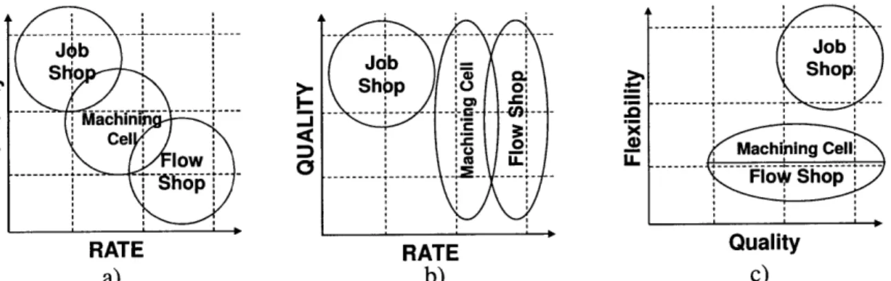
This set of variables can be used to accurately describe the characteristics and performance of almost any manufacturing system. Figure 1.5 shows each type of manufacturing system compared in terms of a) Flexibility vs. Rate, b) Quality vs. Rate, and c) Flexibility vs. Quality, to attempt to provide the reader with further intuition regarding the characteristics of each process relative to one another.
Jeb Job Sho So (D Shop: .0 Mac0i 0 acCel "C 4 C lo Machining Cell j-j low u.: LL -- --- . --- ---- FoWy Shopj
RATE RATE Quality
a) b) c)
Here is where the distinction is made between conventional, macro-manufacturing systems (m-mfg) and micro/nanomanufacturing systems (n-mfg). As such, and in keeping with Westheimer', it would seem the best choice would be to now use the knowledge of current manufacturing system technology as well as different types of nanomanufacturing processes to determine which manufacturing system is best suited for a given nanomanufacturing process. The manufacturing variables used to describe each process will then be used to recommend a specific manufacturing system be utilized or modified in order to maximize the capability of the nanomanufacturing process it is being used to enable.
1.4
Nanomanufacturing Systems
According to Lyons, " nanomanufacturing can be defined as all manufacturing activities that collectively support an approach to design, produce, control, modify, manipulate, and assemble nanometer scale objects and features for the purpose of fabricating a product or system that exploits properties seen at the nanoscale". Currently, instruments for enabling nanomanufacturing processes have satisfied the "control, modify, and manipulate" aspects of nanomanufacturing, now nanoscale products must be able to be "produced" on a large scale in order to realzie their full potential [5].
Conventional wisdom for any instrument or device suggests that in order for any process that is enabled by said instrument or device to become commercially viable, the device must be able to produce parts or products in a cost-effective manner. Over 100 years of knowledge and experience are available to a design engineer when considering integration of a machine tool enabling macro-scale processes (milling, turning, water-jet cutting) into a production/manufacturing line. Additionally, the basic technological architecture is also available on the macro-scale. Hundreds, if not thousands of plants and production lines are utilizing these technologies each day to provide our society with the products it demands.
An "instrument" cannot be used in a manufacturing system to enable a process when there is potential to design and develop a precision machine to enable that same process at a
"A couple of months in the laboratory can often save a couple of hours in the library" -Prof. Frank Westheimer.
much higher rate. A nanomanufacturing instrument must be modified to be able to be integrated into a nanomanufacturing system. This thesis seeks to identify a set of goals and guidelines to be used when transforming an instrument for fabrication of nano-scale features into a production machine for the manufacture of high volumes of products which utilize those nano-scale features.
In order to fully realize the potential of some nanomanufacturing technologies, they need to be integrated into manufacturing systems, however, instruments currently used in "nano-fabrication" processes are inherently different than their macro-scale counterparts. As a result, the full potential of many nanomanufacturing processes cannot be realized because they are not currently able to be integrated into manufacturing lines. As such, using a deterministic design process an overall machine architecture has been proposed, and a machine tool tailored to a specific nanomanufacturing process (Dip Pen Nanolithography, or DPN) has been reduced to practice, in order to verify it's efficacy at enabling DPN as a manufacturing process.
Feynman, in a speech given in 1959 at Caltech, outlined a process similar to E-beam lithography, which could be used to print the entire Encyclopedia Britannica on the head of a pin [13]. This is one of the first documented discussions regarding "nano-technology", a term that wasn't coined until several decades later. Budworth [14] and Chryssolouris [5] highlight the potential impact nanomanufacturing can have on society if successfully utilized to enable the mass-production of nano-technology-based devices. Given the current small-scale methods used to execute these processes, it is absolutely necessary to design equipment to satisfy the needs of nanomanufacturing processes. The technology required to enable nanomanufacturing processes to produce on a far larger scale than at present is essential to harnessing the true potential of nano-technology. The goal of this thesis is to provide scientists and engineers with a LegoTM-like (normal or duplo) building block, to be utilized to help realize the full potential of nanomanufacturing processes.
As stated earlier, it would be wise to attempt to learn from history, and in some way draw parallels between certain nanomanufacturing processes and their macro-scale counterparts. In order to do this, the PUGH chart in Figure 1.6 can be used with the same manufacturing variables on the horizontal axis, but with different manufacturing process on the vertical axis. If a nanomanufacturing process and "macro" -manufacturing process (a macro-scale process that is currently used in a manufacturing system) were to obtain similar scores in the Pugh chart, then
the manufacturing system used to enable the macro process would be the first type considered to enable the nano process. Using this method, a Pugh chart can be used to objectively identify similarities and create parallels between nano- and macro-manufacturing processes, and thus help in choosing the best manufacturing system for a given nanomanufacturing method.
1.4.1
Nanomanufacturing Processes
The different types of nanomanufacturing processes are as far-reaching and varied as their macro counterparts. They all cannot be described in detail within the scope of this thesis; it would be optimal to present the most common, well-known and well-developed processes to give the reader a good idea as to the range of nanomanufacturing processes that are available. As such, the entirety of Chapter 2 is devoted to nanomanufacturing processes. It describes several in detail, gives examples of their uses, and also provides references for other processes.
1.4.2
Nanomanufacturing Variables
Chryssolouris et al. stated that "The general four classes of manufacturing attributes, cost, time [or rate], quality, and flexibility ... have to apply to nanomanufacturing aspects and can contribute to the optimization of every nano-oriented industrial level process so as to receive the expected results" [5]. While these four manufacturing variables form the basis for describing and analyzing manufacturing processes and systems in general, they must be expanded upon in order to accurately describe nanomanufacturing processes. These variables must include parameters which describe the physics of the process, its sensitivity to typical disturbances encountered in a manufacturing setting, and the potential negative impact that nano-structures could have on the surrounding environment [14]. As an example, when a part that has a characteristic dimension of 20 cm is being machined, it is sometimes acceptable to have errors on the order of microns. In a nanomanufacturing process however, the parts can have characteristic dimensions on the order of 20 microns, and thus micron-level errors will result in dramatic (even catastrophic) variations from part to part for the nano-process.
While these new parameters are not critical to matching a manufacturing system to a process, they are addressed and included here to stress the importance of not losing sight of them after the system has been selected; they are critical to the design of the nanomanufacturing machine. These processes are: feature resolution, alignment accuracy, and environmental impact
[15]. Here, the environmental impact is bi-directional, referring to the sensitivity of certain nanomanufacturing processes to their environments (necessitating clean-rooms, temperature and humidity control, etc.), as well as potential problems associated with nano- and micro-scale products being released into the environment that could be harmful to surrounding ecosystems and human populations.
The parameters which are critical to matching a nanomanufacturing method to its "best process" are the rate, cost, quality, and flexibility. Additionally, the energy, feature resolution, alignment accuracy, and environmental impact also factor into the equation, but are not addressed here for simplicity. These variables are presented in the PUGH chart seen in Figure 1.6. The manufacturing processes off of which to base the design of new nanomanufacturing equipment can be determined using the metric-mapping process outline in Chapter 3.
0 4 0 -0 law a) 4 1 JobShop
-1 +1 +1 -1
-1
- - -Machining Cell0
0
0
0
0
- - -Flow Shop +10
-1 +1 +1 - --Figure 1.6: PUGH chart comparing manufacturing systems to process parameters.
1.4.3
Metric Mapping for Conventional Processes
How does a design engineer create nanomanufacturing equipment? Is using a deterministic design process [16] enough to ensure that the final design is adequate and will meet the requirements of the nanomanufacturing process? There must be some inclusion of the history of manufacturing: what has been done before, what has worked well and what didn't work (or failed catastrophically). Simply listing references for design analysis and design parameters, while they are important to the design process, does not adequately address the relationship between what has been proven to be effective in manufacturing and what is needed to enable nanomanufacturing
Manufacturing is manufacturing, whether it be conventional, micro, or nanomanufacturing. Relating different "flavors" of manufacturing together can be done in a variety of ways. For example, consider additive (3-D printing) and subtractive (end-milling) processes as two different types of conventional manufacturing: they are characterized based on the way in which the atoms in the end product are manipulated prior to achieving their final location within the part. Still another process is forging, where material isn't so much as removed or added as it is smashed and molded into a new shape. What are the analogous nano-processes? Dip Pen Nanolithography (DPN) can be considered an analogue to 3-D printing, while nano-EDM can be considered the nano-scale cousin of end-milling.
The question here is, how do you prove that DPN is the nano-scale analogue to 3-D printing. 3-D printing is not yet a viable method of manufacturing things on a large scale, so how
would a design engineer go about designing a machine to enable DPN on a large-scale? A method for drawing parallels between a nanomanufacturing process and similar macro-manufacturing processes would be helpful in guiding a design engineer through the first steps. The design engineer's own ingenuity and creativity can then be used to modify and adjust the method as needed.
1.4.4
Instruments for Nanomanufacturing
Instruments for nanomanufacturing are currently available, and are capable of implementing a given nanomanufacturing process in the laboratory. Consider the following examples of an instrument for nanomanufacturing (the NanoInk NScriptorT M) and a
machine-tool for a nanomanufacturing process which is similar to it's macro-scale counterpart, the Sodick AE05 Nano EDM machine, as seen in Figure 1.7.
Figure 1.7: a) NanoInk NScriptorTM DPN@ system [17]; b) Sodick AE05 Nano EDM machine [18].
The NanoInk NScriptor is an example of an instrument which has been designed with the focus of enabling the nanomanufacturing process in mind, with little consideration given to how integration of a machine into a manufacturing line would be achieved. The NScriptorTM system suffers from high set-up (or cycle) time, on the order of 20 to 30 minutes; it is a scientific instrument, not a machine tool. Tthe Sodick Nano EDM machine, on the other hand, looks similar to vertical machining centers produced by companies like Haas [19] and Mazaak [20], each with a reputation for producing some of the world's best precision CNC machine tools. Nano-EDM is also similar to it's macro-scale counterpart; currently available technologies such as the Belmont MaxicutTM EDM machine seen in Figure 1.8 are evidence that certain nanomanufacturing technologies have begun to move to the factory floor.
Figure 1.8: Belmont Maxicut'' EUM Machine [21j.
It might be intuitively obvious (with a quick look through the latest manufacturing technology catalog) to the more experienced manufacturing engineer which types of macro-manufacturing technology would be useful in integrating the Sodick AE05 nano-EDM machine into a manufacturing line. However, without detailed knowledge of the nano-EDM process, things like environmental controls or workpiece handling and positioning requirements, meeting the technological needs of nano-EDM as a process in a manufacturing environment can prove difficult.
Furthermore, given that the NanoInk NScriptorTM is still a scientific instrument, it is a non-trivial task to determine the optimal machine architecture and layout of material handling structures for enabling DPN. The best practices for integration of DPN machines into a production line are also unknown, and these are questions which are not easily answered from a catalog, or even a comprehensive manual on machine design. In order to answer these question it would require the manufacturing or design engineer to design and implement new technology to meet the unique needs of DPN as a nanomanufacturing process.
Instead of attempting to retro-fit or modify currently available technology, the design process will be followed from the beginning with functional requirements developed from the process characteristics. Starting anew and focusing on designing a new machine (or machine architecture as is done in this Thesis) will not only yield a piece of manufacturing equipment
designed specifically for the process (whether it be DPN, Nano-EDM, etc.), but will also encourage and enable a design engineer to learn a design methodology for designing equipment for nanomanufacturing. The long-term benefits are apparent in that a method can be repeatedly applied to multiple different nanomanufacturing processes, and can be used by others to help them efficiently and effectively design their own nanomanufacturing machines.
1.4.5
Nanomanufacturing Equipment
There is a difference between a scientific instrument for enabling a nanomanufacturing process, and a piece of manufacturing equipment utilized to perform a nanomanufacturing process. The former is usually developed in a laboratory setting, where the goal is to perfect a certain process, or study its characteristics and other aspects of the process. The latter is the result of a demand or need for large quantities of the product created by the process enabled by the instrument. Nanotechnology has huge potential [5, 13, 14], but in order to reach that potential, there must be manufacturing systems available which can support the creation of
enough product so as to meet demand, which is not possible using an instrument.
In order to quantify and elucidate the differences between instruments and manufacturing equipment for enabling nanomanufacturing processes, and to identify what must be done in order to transform an instrument used to enable a nanomanufacturing process into a nanomanufacturing machine, a method will be presented which will allow for both a quantitative and qualitative comparison of the characteristics of different conventional manufacturing processes with a specific nanomanufacturing process; the end goal being to use conventional manufacturing technology as a starting point for the development of nanomanufacturing technology.
Any manufacturing machine, including nanomanufacturing machines, must be designed with physical characteristics of the manufacturing process in mind, like necessary throughput to keep the process economical, the workpiece handling machinery, and waste disposal. Furthermore, the physical limits of the machine (in addition to things like positional accuracy and thermal sensitivity), as expressed in terms of Mean Time To Failure (MTTF), and Mean Time to Repair (MTTR), place restrictions on which types of machine elements are best suited for incorporation into the machine. For example, a machine which moves a large mass at high
velocity in order to keep throughput high, must be designed to be stiff, mitigate vibrations, and also have small thermal drift in order to meet the demands of a manufacturing environment.
Mean Time to Failure is described by Gershwin [22] as the "average duration of an up period", where "up" period is the time the machine spends working and producing materials. Mean Time to Repair is the average duration of the time that the machine spends down while waiting to be repaired. While both of these should be factored into calculations of a machine's rate of production, the level of detail required to give this calculation justice is outside the scope of this thesis.
An instrument has little to none of these restrictions, as down-time for an instrument does not always mean that money is being lost, as is usually the case with a manufacturing machine. A good analogy to highlight the differences between a nanomanufacturing machine and an instrument for enabling a nanomanufacturing process would be to think of the nanomanufacturing machine as a car which must drive from one side of the United States to the other in a given period (to meet the needs of a customer on the opposite coast), while the nanomanufacturing instrument can be likened to a stock car competing in a NASCAR race. While both must be high-performance, precision machines, the former can be serviced only when it is convenient and the resources are available to do so, must operate for long periods without interruption, and can be driven in a sufficient manner (to maximize profit) by a wide range of people. The stock car, on the other hand, can be serviced at the convenience of the operator, any problems can be addressed almost immediately, and the stock car requires a high degree of skill and expertise to operate successfully.
1.5
Scope
The goal of this thesis is to highlight the fact that nanomanufacturing is in its infancy, and that parallels can be drawn between conventional manufacturing and nanomanufacturing to catalyze the development of the technology required to support nanomanufacturing processes. Also, this thesis can be used to help educate the reader about what can be learned from the history of conventional manufacturing. A basic knowledge and understanding of manufacturing systems (Chapter 1), nanomanufacturing processes (Chapter 2), and a metric-mapping methodology for developing nanomanufacturing systems based off of conventional manufacturing systems (Chapters 3 and 4) can be obtained from reading this thesis. Chapter 4 is
also a case study which highlights the efficacy of the methodology presented in Chapter 3, and the design of the resulting machine architecture, work-piece handling and material processing equipment is described in detail in Chapter 5. The use of the machine to perform a nanomanufacturing process will be demonstrated and areas for improvement or other uses of the method and machine architecture will be discussed (Chapter 6).
CHAPTER
2
NANOMANUFACTURING
2.1
Opportunities in Nanomanufacturing
Instruments cannot be used in manufacturing systems when the product of that system is primarily the result of an operation performed by that instrument2. The need for a nanomanufacturing machine begins first with the conception of a nanomanufacturing process. Once any process has been realized and demonstrated to be utilitarian in nature, in order for it to be implemented on a large scale (and thus remain economical in a manufacturing sense) technology must be developed to support the process. The process must be implemented with high-throughput in mind; nanomanufacturing processes suffer from the fact that their output product is physically small (hence the "nano"), and therefore must produce large quantities of product in order to meet the requirements of commercialization.
When considering a nanomanufacturing process that is implemented in the laboratory on an instrument, it is important to realize that in order to be commercially viable, the instrument must be modified to integrate into a manufacturing system. Manufacturing technology that is currently used for large-scale (in the physical, bulk sense of the word) manufacturing must be modified to be able to integrate with a nanomanufacturing system. It is the goal of this thesis to identify a set of design rules and guidelines to be used when transmogrifying an "instrument" for
2 One example of instruments utilized in manufacturing systems today are x-ray scanners used to look for cracks in
high-performance metal components; they are used for analysis, and their use can be controlled for with accurate process control

![Figure 2.6: Example of EBL proximity effects (top), and gratings written using SPL (bottom) [41].](https://thumb-eu.123doks.com/thumbv2/123doknet/14687805.560568/54.918.177.808.109.635/figure-example-ebl-proximity-effects-gratings-written-using.webp)
![Figure 2.7: Scanning Tunneling Microscopy Lithography in deposition mode, depositing a copper cluster onto a gold substrate [25].](https://thumb-eu.123doks.com/thumbv2/123doknet/14687805.560568/55.918.160.770.356.664/figure-scanning-tunneling-microscopy-lithography-deposition-depositing-substrate.webp)
![Table 3.1: Taxonomic classification of different types of manufacturing processes as described by Todd [[66]].](https://thumb-eu.123doks.com/thumbv2/123doknet/14687805.560568/69.918.133.788.128.474/table-taxonomic-classification-different-types-manufacturing-processes-described.webp)

