DESIGN OF MICHELIN CALENDER 800 QUICK PACE CHANGE ASSEMBLY
by
Jayakumar Gurusamy Submitted to the
Department of Mechanical Engineering
in Partial Fulfillment of the Requirements for the Degrees of MASTER OF SCIENCE
and
BACHELOR OF SCIENCE at the
MASSACHUSETTS INSTITUTE OF TECHNOLOGY June, 1996
@ Jayakumar The author hereby to distribute copies
Gurusamy, 1996. All rights reserved. grants to MIT permission to reproduce and
of this thesis document in whole or in part.
/ A/
Signature of Author
/7
Departent of Mechanical Engineering/" February, 1996Certified by
aProfessor Igor Paul
ssociate Professor, echanical Engineering Thesis Supervisor
Accepted by I~A~A.CF*~US~TTS ~;*~JS*~*2
OF TECHNOLOGY
JUN 2
6
1996
Eng,
Professor Ain A. Sonin Chairman, Committee on Graduate Students
DESIGN OF MICHELIN CALENDER 800 QUICK PACE CHANGE ASSEMBLY
by
Jayakumar Gurusamy
Submitted to the Department of Mechanical Engineering on February 23, 1996 in partial fulfillment of the
requirements for the degrees of Master of Science and Bachelor of Science
in Mechanical Engineering
ABSTRACT
The calender 800 produces metallic tissue that is used as steel belts in
Michelin tires. The capacity of the calender 800s in North America does not meet the requirements of production. Any improvement in the output of this machine would increase the production capacity of tires. One area of the machine that has been identified for improvement is the pace change area. Most of the changeover time of the calender 800 from one type of metallic tissue to another is dedicated to this area; changeover of the area, known as a pace change, consumes between 30 to 90 minutes of time.
The objective of this project is to design a system to allow operators to perform a pace change more quickly. Three concepts are formulated and studied to reduce the pace change time. Concept 3, which uses a one-axis robot to reset the positions of cables that are imbedded in the metallic tissue, is most promising. In addition to saving time, the concept improves on operator safety and eye strain which are also of concern in the existing pace change area.
Thesis Supervisor: Professor Igor Paul
ACKNOWLEDGMENTS
I would like to thank my thesis advisor, Professor Igor Paul, for his support of this project and for his guidance throughout the thesis preparation. I would also like to thank Professor Peter Griffith, the M.I.T. faculty representative for the Michelin Tire Corporation, for his helpful suggestions.
I would like to acknowledge the Michelin Tire Corporation for its support of the Engineering Internship Program at M.I.T. I would like to thank the members of the engineering department at the US1 plant for their help
throughout the project. In particular, I am grateful to Dean Habrun and Steve Yant for their strong support of this project and of the internship program. Finally, I would like to thank my parents and my brother for their love and support.
TABLE OF CONTENTS Abstract. . 2 Acknowledgments. . . . 3 Table of Contents. .. . 4 List of Figures. . . . 6 List of Tables. . . . 7 Chapter 1. Introduction. .. .8 1.1 Objectives
1.2 Motivation for Project 1.3 Background
1.3.1 Calender 800 Operation
1.3.2 Operation of Pace Change Area 1.3.2.1 Pace Change Area Structure 1.3.2.2 Pace Change Procedure 1.3.3 Variables in a Pace Change
1.3.4 Problems with Present Pace Change Procedure 1.3.5 Goals of Project
1.3.6 Constraints
Chapter 2. Design Approach. . . . 23
2.1 Introduction
2.2 The Design Process
2.2.1 The Creative Process 2.2.2 The Analytical Process 2.3 Reducing Equipment Setup Time
Chapter 3. Simplification of Existing Equipment. 29
3.1 Need for Simplification 3.2 Approach to Simplification
3.3 Simplification of the Pace Change Area
Chapter 4. Concept 1. . . . 34
4.1 Need for New Technology 4.2 Basic Idea
4.3 Concept Variations
4.4 The Pace-Changing Mechanism 4.5 Background
4.5.1 The Elastic Element 4.5.2 Wear
4.6 Development of Concept 1 4.7 Reason for Failure
Chapter 5. Concept 2. . . . 44
5.1 Introduction 5.2 Design Layout
5.3 Pace Change Procedure 5.4 Concept Development
5.4.1 Special Component Requirements 5.4.2 Component Designs
5.4.2.1 Adjuster Assembly 5.4.2.2 Storage Unit
5.4.2.3 Guide Box Assembly 5.5 Control Layout
5.6 Conclusions
Chapter 6. Concept 3. . . . 62
6.1 Introduction 6.2 Design Layout
6.3 Pace Change Procedure 6.4 Component Designs
6.4.1 Adjuster Assembly
6.4.2 Half-Pace Roller Assembly 6.4.3 Full-Pace Roller Assembly 6.4.4 Cable-Holding Bar
6.4.5 Transfer Clamps
6.4.6 Temporary Storage Tray 6.5 Adjuster Control System
6.5.1 Control Layout 6.5.2 Motor Size
Chapter 7. Conclusions & Recommendations. 87
7.1 Conclusions
7.2 Recommendations for Future Work
Appendix A. Present Pace Change Procedure. 89
Appendix B. Algorithm for a Pace Change. 90
LIST OF FIGURES
Figure 1.1. Figure 1.2. Figure 1.3. Figure 1.4. Figure 1.5. Figure 2.1. Figure 2.2. Figure 3.1. Figure 4.1. Figure 4.2. Figure 4.3. Figure 4.4. Figure 5.1. Figure 5.2. Figure 5.3. Figure 5.4. Figure 5.5. Figure 5.6. Figure 5.7. Figure 5.8. Figure 6.1. Figure 6.2. Figure 6.3. Figure 6.4. Figure 6.5. Figure 6.6. Figure 6.7. Figure 6.8. Figure 6.9.Side View of Calender 800 Assembly. Side View of Pace Change Area .
Typical Profile of Half-Nappe Roller Grooves. Full-Pace Roller Delivery System..
A Typical Comb. . . . Primary Design Domains . .
The Design Loop. . . .
New Layout of Pace Change Area.
Layout of Concept 1 . . .
The Stack. . . . .
Pace Change Using the Stack. . Layout of Lift-and-Shift System . Concept 2 Area Layout. . . Top View of Half-Pace Subassembly. Components of Concept 2 . .
Adjuster Assembly . . .
Cable Unit. . . . .
Storage Unit . . . .
Guide Box Assembly. . .
Control System Layout for Both Adjusters. Main Assemblies of Concept 3. .
Some Parts of Pace Change Area .
Typical Cable Block . . .
Cable Block in Slot . . .
Moving a Cable Block. . .
Overlapping Cable Blocks at 2.2 m m Spacing.
Adjuster Assembly . . .
Positioner Extended "Forward". . Half-Pace Assembly. . . . 10 12 14 16 18 25 25 32 35 39 39 42 46 47 49 53 55 56 58 60 63 66 68 68 70 70 72 73 75
Figure 6.10. Figure 6.11. Figure 6.12. Figure 6.13. Figure 6.14. Figure 6.15. Figure 6.16.
Full-Pace Roller Assembly. .
Pneumatic Circuit for Full-Pace Roller Assembly. Cable-Holding Bar & Fixed Support.
An Assembled Transfer Clamp .
Temporary Storage Tray . .
Control Circuits for Adjusters . Bond Graph Model of Adjuster .
LIST OF TABLES
Table 4.1. Main Advantages & Disadvantages of Concept Variations. 37
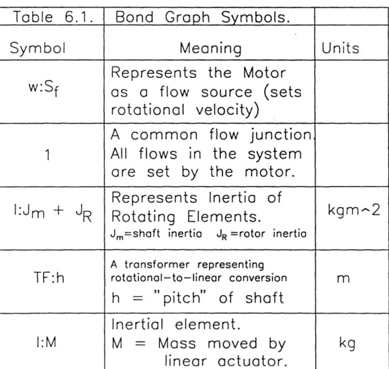
Table 6.1. Bond Graph Symbols. . . . 85
77 78 80 80 82 84 85
Chapter 1. Introduction
1.1 Objectives
The objective of this thesis is to design a system to allow operators of the Michelin calender 800 machine to perform a pace change more quickly. In addition, the design should simplify the procedure, improving safety and reducing eye strain.
1.2 Motivation for Project
The calender 800 produces metallic tissue which eventually is placed into tires as steel belts. Of course, for various tire lines, unique metallic tissue is required. Presently, the total output of the calender 800s in North America is below the required amount. The time required to accomplish a
changeover, known as a pace change, from one type of metallic tissue to another ranges from 30 to 90 minutes. A reduction in this time will directly increase the metallic tissue output of the calender 800 and the production capacity of Michelin manufacturing facilities. This improvement in capacity is the main motivation for this project.
In addition, two other concerns motivate this study. One is operator safety. During a pace change, operators place themselves in awkward positions that have a great potential for injury. The second concern is eye strain. The metallic tissue produced by the calender can contain up to 800 steel cables; during a pace change, the cables are moved individually by operators to new positions. Since only a few millimeters separate each cable, operators must strain their eyes to locate each cable and its new position.
1.3 Background
1.3.1 Calender 800 Operation
The calender 800 produces metallic tissue (two rubber sheets that sandwich steel cables). The cables run parallel to one another and are equally
spaced; the spacing (pace) can range from 1.1 mm to 3.15 mm. To accomplish this task, the calender 800 utilizes four major subassemblies: the block creel, the pace change area, the rubber feeding mechanisms, and the finishing operations. Shown in figure 1.1 is a side view of most of the calender 800 (only part of the block creel is shown). The machine is very large with numerous components and requires three full-time operators to perform various tasks throughout the process of producing metallic tissue.
The block creel is a large storage unit for the bobbins of cable that feed into the rubber sheets. The bobbins are placed onto pegs and the cables are
guided through a series of pulleys. The cables are made of steel with a brass coating. In addition, in the block creel contains a tension-setting mechanism for each cable. When the tension in a cable becomes too high or too low, the mechanism triggers a lever which stops the calender; the cable tension can range between 3 and 24.5 newtons. Finally, the cables leave the block creel on six separate planes as shown in figure 1.1. The six levels are required for proper separation between the cables when using the present design for guides.
From the block creel, the cables flow into the pace change area. In this area, two main objectives are accomplished. The primary task of this area is to set the spacing or the pace between the cables that are to be imbedded between rubber sheets. In addition, any additional cables that are not being used in the product being run are removed and stored. When these stored cables are needed in a product, they are tied back into the system. Since the pace change area is the primary focus of this thesis, section 1.3.2 provides a detailed description of this area and of how the tasks are presently completed.
Once the pace and the number of cables are carefully set in the pace change area, the cables flow into the rubber feeding mechanism. Here, two large metal cylinders, called boles, rotate in opposite directions, each cylinder guiding a sheet a rubber. The cables are first pressed onto one of these rubber sheets. Next, the two large cylinders meet at a point as shown in figure 1.1. As
to 2 0
O
uli 0 T 20 O 0 oq (UU ooa result, the cables become embedded between the two rubber sheets. The tackiness of the rubber permanently holds this laminated metallic tissue together.
The finishing operations are accomplished using several machines, each performing a unique task. Once the metallic tissue leaves the boles, it arrives at the trimming machine; this machine determines the amount of excess rubber at the edges of the product and cuts this excess off. Next, the product enters a compensator which eliminates slack in the product that results from any difference in speed between the drives that pull the rubber product through the machine. If this compensator fills with product or empties, the calender is stopped automatically. Finally, the product reaches a wind-up so that it can be wound into rolls and sent to the 10/30 cutter, which converts the metallic tissue into steel belts.
1.3.2 Operation of Pace Change Area 1.3.2.1 Pace Change Area Structure
In the pace change area, the number of cables and the spacing between those cables are set. The existing design is comprised of numerous parts that make this part of the calender extremely congested.
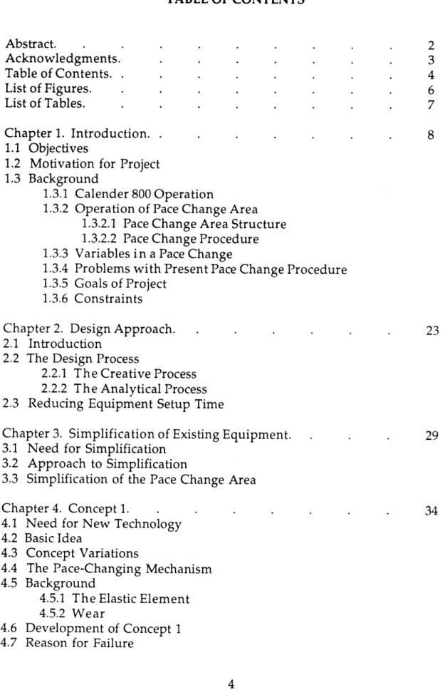
The numerous parts in the pace change area can be grouped into four subassemblies. In figure 1.2 is shown a side view of the area with key
components labeled. Notice that the first units with which the cables come into contact are the guide boxes. Six levels of guide boxes maintain the same six levels of cables that arrive from the block creel. The purpose of the guide boxes is to keep the cables separated so that they do not rub against other cables and so that operators can easily find the desired cable. On each level are seven to eight guide boxes that can slide on a shaft; each guide box contains 15 grooves made on the outer surface of a hollow steel cylinder that rotates on two bearings. Through each of these grooves a cable is placed; the grooves rotate so that the cables do not slide on any surface.
CuIDE
BcvI(S
Riuset2
"rs
s VE
Any significant amount of sliding contact that a cable makes with a surface results in two severe problems. The sliding contact makes the cable curl. This curl in the cable does not allow the metallic tissue to lie completely flat, causing quality problems in steel belts of tires. Secondly, the cable will cut through material that it slides across. Although the rate of wear is not
significant on glass nor on steel, the cable has been known to completely cut through aluminum rollers. For these reasons, most surfaces to which the cables come into contact are made to roll in the direction of cable path.
From the guide boxes, the cables are run into two separate rollers; the top three levels of cable feed into one roller while the bottom three levels feed into another. This area labeled in figure 1.2 is called the half-nappe (or half-pace) assembly; this entire assembly is suspended from the top I-beam using three turnbuckle supports. The two rollers shown in this assembly, known as half-nappe rollers, contain 3 mm deep grooves (typical profile shown in figure 1.3). The number of grooves on each of these rollers is equal to one-half the number of cables that will be in the metallic tissue being produced. The grooves are equally spaced apart with the spacing determined by the pace of the product being run. In addition, the groove pattern is
symmetrical about the center of the cylinder so that the cables will be centered on the rubber. The ends of these rollers are placed in roller-bearing mounts so that they rotate with the motion of the cables. Finally, each half-nappe roller is on a turret that allows operators to position a new roller while the calender is running.
Next, the cables run into the full-pace roller assembly, converging to this roller from the two half-nappe rollers as shown in figure 1.2. The purpose of the full-pace roller is to place the cables onto the rubber product. The number of grooves in this roller is equal to two times the number of grooves in a half-nappe roller. The maximum length covered by grooves is 800 millimeters on both the half-nappe and the full-pace rollers. The groove depth on the full-pace rollers is less than the diameter of the cables; as a
CO 0 0 C 0 0 U" -Pi
result, a portion of all cables protrude from the roller, allowing them to be pressed onto the rubber product. The full-pace roller is on a turret that contains a total of two rollers; this turret allows the operators to insert a full-pace roller into the "waiting" position while the calender is running. To bring the new roller into the working position, the operators force the entire
turret to lift off of the rubber product, rotate 180 degrees, and then return back down onto the rubber product.
The final subassembly in the pace change area is the full-pace roller delivery system. This system's functions are to bring a new roller from
storage to the turret and to move a used roller from the turret to storage. This subassembly is shown in figure 1.4; as shown in the figure, the system is
composed of two parts, the hoist and the carriage. The hoist travels between the storage area and the carriage, while the carriage travels from the hoist to the turret. The carriage contains a pneumatic actuator that is used to pick up the roller in the "waiting" position of the turret. Then, the operators roll the carriage back to the hoist. The hoist picks up the roller and moves it to
storage and brings a new roller from storage. Once the hoist places this new roller onto the carriage, the carriage moves forward and pushes the roller into the turret. It is important to note here that the carriage and the full-pace roller assembly sit on the rubber feeding unit that contains the two large cylinders that press the two sheets of rubber together.
1.3.2.2. Pace Change Procedure
A pace change is performed by three operators when a different metallic tissue is to be produced on the calender 800. The change of pace in the steel belts of tires has a dramatic impact on tire performance. In addition, using less cable for tires not specified for high performance applications (i.e. car racing) saves Michelin a substantial sum of money. For these reasons, a pace change must be performed carefully to ensure that cables are placed in the proper positions.
-I i rv CIL Li' .r' it CL V C r\ r-1 LT cu CI k ~1 o h~ ca n. F4 r; =1 bO F4
"new" half-nappe rollers are placed in their respective turrets. In addition, the required tooling to accomplish the pace change is obtained from storage and brought to the pace change area. In this section is given a description of the main steps in the procedure; for a full step-by-step procedure, refer to appendix A.
Once the calender is stopped, the half-nappe turrets are rotated to bring the new half-nappe rollers into their working positions. Next, the operators place each cable individually into its groove on the half-nappe rollers. In addition, the operators remove or add cables into the system as necessary. To remove cables from the system, the cables are simply cut and tied to stationary rods. When these cables need to be added back into the system, they are
untied from the rods and tied onto cables already in the system; when the calender is run forward, the added cables are pulled into the product allowing them to be placed into the half-nappe roller grooves. This step of placing cables and of changing the number of cables is the most time consuming and tedious step in the pace change.
Once the cables are properly placed in the half-nappe rollers, the new full-pace roller is brought into position and a tool known as a comb is used to move the cables from the half-nappe rollers onto the full pace roller while maintaining the spacing established in the half-nappe rollers. Figure 1.5
shows a typical comb; a different comb is used for the various cable paces. Once the comb is moved from one half-nappe roller to the full-pace roller,
the calender is slowly run forward for a few seconds so that the cables move onto the grooves on the full-pace roller (this process is known as jogging). Then the comb is removed and used to repeat the procedure with the other half-nappe roller.
Finally, the operators place an intermediate roller into position as shown in figure 1.2. The function of the intermediate roller is to force the front set of cables back onto the full-pace roller so that a greater area of contact between the full-pace roller and the cables is created. This greater area
18
. f
S
Lj
j
ensures that the cables do not jump out of the grooves in the full-pace roller. Before starting the calender, the distance of the full-pace roller and the rubber product is checked by running a metal bar underneath the full-pace roller and measuring the thickness of the resulting bar with a micrometer. If the measured thickness is not at the desired value, the full-pace roller turret is moved vertically until the correct thickness is achieved. Once achieved, the calender is started to produce the new metallic tissue. Of course, if cables were tied into the system, the first few yards of product must be discarded.
1.3.3. Variables in a Pace Change
Several factors vary in different qualities of metallic tissue produced by the calender 800. These factors and the range they cover are critical to any new design of a pace change procedure. The factors and each factor's associated range include:
* Pace (1.1 mm-3.15mm)
* Cable Diameters (.6, .8, and 1.0 mm) * Number of Cables (Up to 800 cables)
* Rubber Quality (thickness & composition)
The pace is the spacing of cables in the metallic tissue and is equal to the groove spacing on the full-pace roller; however, the spacing on the half-nappe rollers is twice the pace. Therefore, the spacing of the half-half-nappe roller
grooves can range between 2.2 mm and 6.3 mm. The cable used in metallic tissue is made of steel with a brass coating. The 3 cable diameters listed are the ones used presently at Michelin's US1 manufacturing facility; however, other cable types have been used in the past and could be used in the future. Although not presently being used, fretted cable have been used in the past. Fretted cable has a separate wire that wraps around the cable in a helix.
1.3.4 Problems With Present Pace Change Procedure
decades in both North America and in France. When the calender was first designed and used to produce metallic tissue, the calender's production rate was well above some of the other processes in producing tires. Over the years, as capacities of the other processes have been improved, the calender 800 has gradually gained attention as it no longer enjoys the luxury of being one of the faster processes. Presently, the calender 800 is one of the
bottlenecks in the manufacturing process of tires at Michelin.
Presently, production of metallic tissue is carefully planned and monitored to ensure that necessary qualities are produced when needed. However, the calender 800 is expected to become a major problem in the coming years as it further falls behind in production. As a result, in recent years, Michelin has reviewed the calender 800 process to determine possible ways to increase its production rate of metallic tissue. It has been determined that a large amount of downtime occurs for a pace change; generally, a pace change consumes anywhere from 30 to 90 minutes to complete depending on several factors including the magnitude of the pace change, number of cables to be removed or inserted, and on the experience of operators. Recently, a search has been made to shorten the time required; nevertheless, the search has proven fruitless. As a result, the pace change time remains the main concern associated with the calender 800.
Although the change time is the main concern, several other problems exist in the calender 800 that deserve attention. Operator safety in the pace change area needs careful study. When cables are placed into half-nappe roller grooves, when cables are added/removed from the system, and when cables are combed into the full-pace roller, operators climb into the machinery high above the shop floor to gain access to the equipment. This procedure has a great potential for injury; operators can bump their heads or fall from the machinery. This risky condition is a result of the numerous parts in the pace change area, making the area highly congested, obstructing operator access.
Another safety concern in this area is heavy eye strain. When
operators must place the cables in half-nappe roller grooves, operators must continually locate the correct cable that goes into a specific groove from the numerous cables in the system. Since the cables are extremely close to one another, the task of locating cables is extremely tedious and strains the eyes of operators.
Knots placed in cables pose another problem to the operation of the calender 800. In a procedure called a bobbin change, bobbins in the block creel are replaced with new bobbins of cable. The cable from the new bobbin is simply tied to the cable from the old bobbin that is already in the system using a double knot. When these knots reach the half-nappe rollers, some cables jump out of their grooves; generally, 50-60 cables jump out. These out-of-pace cables must be placed back into their grooves by the operators. Since this is done with the calender stopped, repositioning out-of-pace cables results in loss of production.
The full-pace roller assembly is another area that could be improved. Presently, the roller is placed at a set distance from the bole carrying the rubber product. Within any given rubber quality, however, the thickness of the rubber can vary; when this occurs, the cables are imbedded into the rubber at different depths. It is more desirable, however, to set the cables into the rubber product at the same depth throughout the roll of rubber tissue. If this could be done, the cables would be centered when sandwiched between the two rubber sheets resulting in a higher quality metallic tissue. Placement of cables at the same depth, however, is not possible with the existing full-pace roller assembly.
1.3.5 Goals of Project
Some existing problems with the calender 800 are discussed in section 1.3.4. The specific objectives for this design thesis are as follows.
A. Reduce pace change time. On the calender 800, a pace change requires
30 to 90 minutes to complete. The primary objective of the project is to significantly reduce the amount of time to accomplish a change.
B. Improve operator safety. Operators place themselves in awkward and
dangerous positions during the pace change, largely resulting from a lack of accessibility. Greater accessibility is desired.
C. Reduce operator eye strain. Operators presently must strain their eyes to
locate and move each cable.
D. Incorporate a pressure-driven full-pace roller. To imbed cables into the
rubber sheet at a constant depth, it has been suggested that constant pressure be placed on the roller. When the rubber thickness changes,
the roller would rise and fall as needed.
E. Eliminate out-of-pace cables resulting from knots. Knots placed in
cables result in cables jumping out of the grooves in the half-nappe rollers. A solution is needed to eliminate the time required to reposition these cables.
1.3.6. Constraints
To produce a usable solution, cost of the design needs to be kept to a minimum without sacrificing performance. To minimize cost, two
constraints should be followed. First, the tooling used in a pace change should not be changed significantly. The existing tooling is expensive and numerous; separate tooling (rollers, combs, etc.) is used for the various values of pace; replacement of this tooling would make the cost of any design
prohibitively high. Second, a design should be sought to impact a minimal number of assemblies in the calender without sacrificing the functional independence of these assemblies. Using this approach, the number of components needing redesign is kept minimal.
Chapter 2. Design Approach
2.1 Introduction
Since this project involves existing machinery, the design process utilized to find a workable solution becomes somewhat constrained. The calender 800 is a large system of several subassemblies performing various functions necessary to create metallic tissue. As a result, any modifications made to one area of the calender must not compromise the functionality of the other subassemblies. This constraint placed on the design by the
assemblies on the periphery of the pace change area demands that a careful design procedure be followed.
The first step in the design process is to gain a thorough understanding of the entire system. Without a good understanding of all machinery
involved, the designer can not determine how a proposed solution impacts other assemblies. It is possible, as described in section 2.2, for a proposed solution to make the calender 800 a coupled system; if this occurs, the
calender would no longer be usable. Therefore, when studying a system, each component's function and its influence on the other components must be determined.
Once the entire system is understood, the objectives of the project must be determined from the customer attributes (Suh 1990, 34). Often, this step is accomplished using a quality function of deployment (QFD). In a QFD, the customer attributes are mapped into functional requirements; the functional requirements are customer attributes converted into engineering terms. Functional requirements state the desired outcome in terms of measurable quantities; the perceived needs should be satisfied with a minimal set of functional requirements (Suh 1990, 28).
Determining the constraints placed on the solution is just as important as determining the functional requirements because the constraints provide the boundary of acceptable solutions. Generally, constraints impact multiple
areas of a design. For example, a cost constraint impacts all components in a design. As long as a proposed design does not exceed the imposed constraints, the design is acceptable.
2.2 The Design Process
Once the top-level functional requirements (FRs) are determined from the customer attributes, the designer can begin determining how to fulfill these FRs. Figure 2.1 shows the 3 primary design domains: the functional domain, the physical domain, and the process domain. The functional domain contains the set of functional requirements established by the designer, while the physical domain contains the tangible embodiment that satisfies the FRs (Suh 1990, 26). The process domain includes the manner in which the items in the physical domain will be manufactured. The
determination of design parameters (DPs) to satisfy functional requirements (FRs) and of process variables (PVs) to satisfy DPs is known as mapping.
Mapping is a nonunique process in that multiple solution sets are possible for a given problem definition.
Figure 2.2 illustrates the design process utilized to determine the design parameters in the physical domain (Wilson 1980). The illustration includes a marketplace loop that could be replaced in manufacturing equipment design by the department requesting the design. The step of formalizing the needs is discussed in section 2.1. Once established, engineering creativity must be utilized to synthesize a solution; analysis and tests are then performed to determine if the solution properly satisfies the functional requirements. As shown, the mapping process involves two distinct phases: the creative stage and the analysis stage. The creative process yields solutions and the analytical process determines their worthiness.
2.2.1 The Creative Process
To generate potential design solutions, engineers can employ numerous techniques that boost creativity. Although the mechanisms of
FUNCTIONAL PHYSICAL PROCESS
DOMAIN DOMAIN DOMAIN
Figure 2.1. Primary design domains.
Shortcomings:
Reformulate discreiancies.
F
constraints Product attributes
Product, prototype,
process
/
/
creativity are not nearly as well understood as techniques of analysis, some methods have been found to stimulate the imagination. It is important to note that all new ideas involve some degree of risk; a good designer is one who is willing to accept failures in the search for a winning solution (Suh
1990, 29). The analytical process helps to reduce this risk by allowing the designer to identify solutions that contain fundamental flaws and that are doomed to failure before large monetary amounts are spent on pursuing those solutions.
One effective approach to creativity is building on metaphors.
Metaphors allow comparisons to be made between the meaning and qualities of one thing and those of another. In this technique, something that is not understood is compared to things that are understood; the comparisons lead to new ideas by allowing the mind to see the problem in different ways (Hanks and Parry 1983, 69). With the understanding of the unknown gained from the metaphor, other metaphors can be created to further increase
knowledge of the unknown, leading to additional ideas.
Another useful technique to promote creativity is visual
brainstorming (Hanks and Parry 1983, 80). In visual brainstorming, ideas are sketched on paper as they come to mind; these sketches make the abstract notions more concrete, allowing those ideas to stimulate new ideas. The sketches also reveal any gaps in thinking, forcing the mind to see the problem in a different light. When visual brainstorming, ideas should not be judged. All thoughts that come to mind should be put on paper, allowing the mind to freely make connections between the thoughts. Judgments should be made only after the process is completed.
2.2.2 The Analytical Process
The analytical process involves the use of engineering know-how and judgment to assess the ideas obtained from the creative process. The design axioms help to facilitate this process. In this section, a brief summary of the axioms and their implications to machine design are given.
The axioms can be stated in several forms; the procedural form can be stated as (Suh 1990, 391):
Axiom 1 The Independence Axiom
Maintain the independence of FRs. Axiom 2 The Information Axiom
Minimize the information content.
The independence axiom declares that when a design parameter (DP) is
perturbed, only one functional requirement (FR) should be affected. If one DP influences more than one FR, the performance of the system becomes
extremely difficult and often impossible to control; this type of design is known as coupled. The information axiom deals with the complexity of the design; basically, the statement declares that the design should be made as simple as possible. Designs that maintain functional independence should first be sought and then the information axiom should be utilized to choose the best of these designs. Although the axioms seem at first to be obvious and simple, designers without a good understanding of these axioms often violate them leading to excessive time spent in pursuing a bad idea. Numerous corollaries and theorems, which can be used as more specific design rules, can be derived from the axioms (Suh 1990, 391). Of course, the designer must also have a solid grasp of engineering fundamentals to effectively apply the
axioms of design.
2.3 Reducing Equipment Setup Time
To reduce the changeover time on industrial equipment, several specific areas in the setup process should be studied and modified (Hay 1984). Hay, in his paper, suggests that any setup time can be reduced by 75% no matter how complex the machinery or the changeover. Although he strongly recommends against redesigning equipment as the primary approach to setup time reduction, when a redesign is deemed necessary, some of his suggestions can be extremely useful to a designer.
Identification of internal and external steps in the setup is of primary importance (Hay 1984). Internal steps are those that can only be performed while the machine is stopped. External steps are those that can be done while the machinery is running; methods must be found to accomplish these steps before the machine is stopped or after it is restarted.
A second category of changes is classified as adjustments. One type of adjustment occurs when equipment is made to be infinitely adjustable over a specified range. Usually, infinite adjustment is provided because the exact use of the equipment is not known at time of design. However, in use, many times only a few points in the range are utilized. If such a situation is
identified, it is usually possible to add some form of stops at those points to eliminate the need for measurement. Such a change will dramatically reduce the time involved to reposition equipment from one point in the adjustable range to another point.
Clamping should be preferred to bolts for holding items together when the items must be released during a changeover. Of course, this can be done only when sufficient space is available and when clamps can provide the necessary holding force. Bolts and other threaded components consume a
tremendous amount of time to fasten and unfasten; in addition, they usually require tooling that can be lost. Clamps generally require only one or two motions to be activated or inactivated.
A final area to look for time reduction can be classified as problems (Hay 1984). A problem is anything that interferes with a quick, trouble-free setup. The correct approach is to eliminate the root cause of the problem and nat to find ways to reduce the setup time despite the problem.
Hay suggests the above four key categories as sources for time reduction on existing designs. Nevertheless, the suggestions should be kept in mind to avoid introducing items from these categories into a design.
Chapter 3. Simplification of Existing Equipment
3.1 Need for Simplification
The calender 800 pace change area as described in section 1.3.2 is highly congested. Numerous parts make this area very difficult to enter when performing a pace change. The lack of accessibility presents several problems to the operators. As explained in section 1.3, a key concern is safety; often, operators hang from the equipment during a pace change. This potential for injury can be addressed by simplifying the equipment to improve operator access. Increased working space would also allow operators to perform the steps in a pace change more quickly. For example, greater access would allow operators to more easily align the comb with the cables when transferring the cables from the half-pace rollers to the full-pace roller.
Simplification of the pace change area would also provide the room necessary to add any new equipment. Presently, as shown in figure 1.2, only a small amount of space is available between the half-pace and full-pace rollers to add any new devices or to modify significantly the existing equipment. The lack of space tightly constrains design options; therefore, by increasing the available space, design solutions become more numerous.
Finally, reducing the number of parts without compromising functional independence decreases the number of replacement parts that must be stocked. Reducing the number of stocked parts provides several key benefits. The effort necessary to ensure that parts taken from stock are
replaced is lessened. In addition, the cost of storage space is minimized with fewer, smaller parts.
3.2. Approach to Simplification
To simplify the existing equipment, it is important to follow a careful procedure. The first step is to thoroughly understand the system and the functions performed by each subassembly. In addition, it is necessary to
identify if any subassemblies influence the performance of the other
subassemblies (functional coupling). Only with such an understanding can a designer determine how an assembly can be simplified or which parts can be eliminated entirely.
The second step is to creatively find potential modifications to the existing equipment that improve accessibility or reduce the number of parts without compromising the functionality of each subassembly. To find these potential solutions, the engineer can employ numerous methods including those identified in section 2.2.1. Once the designer has found some possible solutions, each solution's acceptability must be determined; a solution is acceptable if it satisfies all of the functional requirements of the original design without violating the independence axiom discussed in section 2.2.2.
3.3 Simplification of the Pace Change Area
The functions of each subassembly and the effects of each subassembly on other subassemblies is given in 1.3.2. In the search for simplifying options, two other concerns are addressed. The first is the incorporation of a pressure-driven full-pace roller; to force the roller with pressure, pneumatic cylinders could be built into the end supports of the roller. The cylinders could lift the roller from the rubber product to allow a new roller to be inserted; also, the pressure input into the cylinders could be adjusted to apply the desired pressure to the various product qualities. The size of pneumatic cylinder selected determines the maximum force that can be applied to the roller using the 80 psi available in the plant. The ability to set the speed with which the roller is raised or lowered can be provided in the pneumatic control design. The second concern addressed in the simplification process is the full-pace roller carriage. Operators have complained that the carriage that delivers the full-pace roller from the hoist to the full-pace is difficult to use. The
carriage shown in figure 1.4 contains a pneumatic lift that is supposed to position the roller into the turret; often, the lift fails to properly locate the
roller into the turret. As a result, operators use a steel rod to force the roller into position; this process consumes valuable time and much effort.
An effective solution to the carriage problem is to eliminate the need for a carriage altogether. If the pneumatic assembly that sets the roller onto the rubber product could be designed to travel to the hoist, the hoist could place the new roller directly into this assembly; such a design performs the function of moving the roller into position, the function performed by the carriage in the existing design.
To address these concerns as well as the desires to increase space and reduce number of parts, the layout shown in figure 3.1 is best suited. The cables run from the guide boxes into two pace rollers; from the half-nappe rollers, the cables converge onto a full-pace roller. Both the half-pace and full-pace rollers are on linear slides that permit the rollers to be moved into their change positions. At the change positions, the rollers can be replaced with new ones. Notice that for the half-pace rollers, two levels of rollers are provided so that a new roller can be inserted while the calender is running. The full-pace roller is shown with pneumatic cylinders; the roller slides back to the hoist so that the full-pace roller can be replaced, eliminating the need for a separate carriage.
The proposed layout has several important advantages over the existing pace change area. The most important benefit is the reduction of space consumed by the assemblies. Compared to the existing design shown in figure 1.2, the proposed design is much less congested, providing the room necessary to add any new devices. In addition, operators have a greater
amount of room in which to work; the two operator work areas are labeled in figure 3.1. As a result, the operators need not place themselves in awkward positions during a pace change. Finally, the proposed design contains far fewer parts than does the present pace change area. As a result, fewer replacement parts need to be stocked, reducing inventory costs.
r---<I wLLDz z> ..o -S---I <Q 0Q a-0. D I0 a:-0 Id wOw x DO 0.m o 10 <0 a: O Q)L Q) C 0 C O O Q) 0 4-0 C>N Q) C) LL. w r-J I) f J J )
design. During a pace change, an intermediate roller is placed into position as the final step. The intermediate roller forces the cables from one of the half-pace rollers back onto the full-half-pace roller. The intermediate roller ensures
that the cables stay in the grooves of the full-pace roller. However, the intermediate roller is needed only for the half-pace roller that guides the
cables from in front of the full-pace roller as shown in figure 1.2. When both half-pace rollers are placed behind the full-pace roller as shown in figure 3.1,
the need for an intermediate roller is eliminated. Placement of an
intermediate roller consumes 5 to 10 minutes during the pace change. The changed cable path proposed reduces the pace change time by 5 to 10 minutes.
Chapter 4. Concept 1
4.1 Need for New Technology
As discussed in chapter 1, most steps in the present pace change
procedure are completed by the three operators. Ideas suggested in section 2.3 can be applied to the area to reduce the setup time. However, without the application of any new technology, such modifications would only reduce the time by a small amount.
Two steps in the present procedure consume the majority of the pace change time. The placement of cables into the half-pace rollers requires the greatest amount of time; since operators must locate each cable and its proper position by hand, the task is extremely repetitive and slow. The process of removing cables from the system or adding cables to the system is the next most time consuming step; again, this is a result of having to locate the correct cable and the position in which to store it. As long as these two steps remain manual operations, the pace change time can not be greatly reduced. As a result, it is appropriate to incorporate new technology to automate some of these time consuming operations.
4.2 Basic Idea
To automate the steps of placing cables into half-pace rollers and of moving cables to and from storage, concept 1 attempts to pick up all the cables at once from the half-pace rollers, change the pace between the cables and then place the cables onto the new half-pace rollers. Since cables are spaced at a certain pace between the half-pace and full-pace rollers, the cables run parallel in this region; as a result, it is possible for a pace-changing device to locate these cables. Throughout this thesis, such a pace-changing device is called an adjuster.
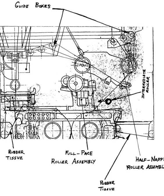
In addition to changing the pace, the adjuster performs the task of removing or adding cables as necessary. Figure 4.1 shows the proposed layout
of concept 1; the actual operation of the device is discussed in section 4.4. In this layout the main mechanism changes the pace; on the sides, is the device (storage unit) which determines which cables to remove or add and then inserts or deletes those cables. For example, if 50 cables were to be removed, each storage unit would cut out 25 cables and clamp them.
Pace-Changing Mechanism Storage Unit Top Clamp Bottom Clamp Storage Unit Top Clamp Bottom Clamp
Figure 4.1. Proposed Layout of Concept 1.
Notice that within each storage unit are two clamps; two clamps are necessary so that cables already in storage can be held while other cables are brought into storage. When new cables are to be placed in storage, the top clamp opens to allow entry while the bottom clamp stays closed to hold onto the cables already in storage. Once all cables not needed in the new roller are brought into storage, the top clamp closes, locking onto all cables in storage. At this point, an operator cuts out these new cables from the rubber tissue using a pair of scissors. The bottom clamp opens to accept these new cables and then closes. The storage unit "knows" which cables to remove by
determining the distance from the center of the adjuster covered by cables to be placed into the new half-pace roller. This distance is simply the product of
the pace and one-half the number of cables to be kept in the system; this distance is the same on both sides of the adjuster since all half-pace rollers are symmetric. By performing the two most time-consuming operations in a pace change, the concept 1 adjuster reduces the pace-change time from 30-90 minutes to 10-15 minutes.
4.3 Concept Variations
To accomplish the functions described in section 4.2, three approaches are possible, each with its advantages and disadvantages. One approach is to create a hand-held tool that operators can position to perform a pace change and then remove once the change is completed. Another approach is to create a new half-pace roller which also acts as an adjuster when a pace
change is necessary; such a roller would change the spacing between the cables and storage units would remove or add cables. The third approach
incorporates the adjuster assemblies into the pace area; the adjuster is this case would be separate from the half-pace rollers. The half-pace rollers would hold the cables when the calender is running, while the adjuster would
receive the cables from the rollers only to perform a pace change and return the cables to the new half-pace rollers.
Some advantages and disadvantages of each approach are listed in table 4.1. The hand-held device would be too large and heavy to be effectively handled by operators. Although a pace-changing half-pace roller would perform a pace change most quickly, creating such a cylinder would be
extremely difficult and expensive. Such a cylinder would have to absorb the constant vibration and wear from the cables. For these reasons, a device built into the calender that picks up the cables from the rollers and then changes
the pace is the best choice to pursue; this device is listed in table 4.1 as the lift-and-shift device.
Main Advantages & Disadvantages of Concept Variations.
ADVANTAGES
DISADVANTAGES
1. Operator maintains complete 1. Large & Heavy control over alignment.
2. Great chance for serious 2. Does not become another damage to operator and
part in pace-change area. device if dropped. (does not congest area)
3. Does not experience heavy
SLJ "load from cable tension.
C)
<Li
1. No heavy strain placed 1. Requires several modifications
"on operator. to the structure of the pace change area.
II 2. A fast procedure.
(')
3. Does not experience wear of sliding cables.
Z
< Li C)
1. No alignment required, 1. Experiences constant wear
L providing easy control from moving cables.
/ to the operator.
2. Must be very large to
O 2. Fastest of 3 options. accept a heavy load and vibration from cables. 3. Maintains contact with
cables at oil times. This ensures that cables will
i
n<
not become out-of-pace.o
I
4.4 The Pace-Changing Mechanism
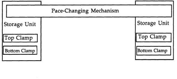
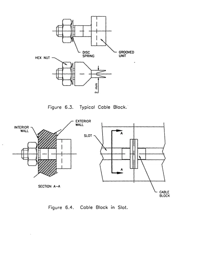
Inside the adjuster, a mechanism, called the stack, changes the pace between the cables. Figure 4.2 shows the components that make up the stack; only two unique components make up the stack: the cable block and the elastic element. The function of each cable block is to hold a cable in place, while the elastic elements maintains equal spacing between the cable blocks. The cable block should be designed to accept all three cable types used by the calender. The amount of deflection that the elastic element can experience without plastically deforming determines the amount of the pace change range that the stack can cover.
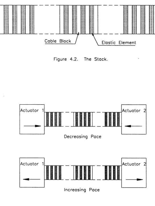
When a pace change is to be performed, the cable blocks in the stack receive the cables from the half-pace roller. Once the cables are in the blocks, two actuators begin to change the pace. If a greater pace is desired, the two actuators move outward, allowing the entire stack to expand. If a reduced pace is desired, the two actuators move inward, compressing the entire stack. Since each elastic element is identical to the others, equal separation is
maintained in both cases. Both cases are shown in figure 4.3.
4.5 Background
Two problems must be addressed for concept 1 to work effectively. The first problem is finding a suitable elastic element that is compact and has a large range of compression; a large compression range is necessary to cover the half-pace separation range of 2.2 mm to 6.3 mm. The second problem is wear. The stack must be held in place by a structure; when a pace change is performed, the elements of the stack slide on the surfaces of the supporting structure. The wear between the sliding surfaces should be kept minimal so that each elastic element displays consistent performance throughout its specified life.
nil'
K
L
=Il
ElK
Cable
Block
/
\
Elastic
Element
Figure 4.2. The Stack.
Decreasing Pace
Increasing Pace
Figure 4.3. Pace Change Using the Stack.
~K~Lllh1I[
4.5.1 The Elastic Element
From the numerous elastic elements available in the market, a compact elastic element with a large compression range must be chosen. Compression springs available from many manufacturers are too long to fit in the available space and do not compress to achieve the separation of 2.2 mm. However, many other possibilities exist, including bellows, belleville
springs, disc springs, rubber sandwiches, and cantilevered springs (Chironis 1961).
Each possibility has its own unique qualities that determine its range of application. For the stack, the best choice for the elastic element is the disc spring. Disc springs are extremely compact and can compress significantly; in addition, by placing the disc springs either in series or parallel, it is possible to achieve various load-deflection characteristics that are predictable.
4.5.2 Wear
The sliding contact between the stack and the supporting structure experiences friction and wear. The most widely accepted theory on wear between two solid surfaces is the adhesion theory (Rabinowicz 1965).
According to this theory, the points of contact between the two surfaces stick to one another; as a result, these bonds must be broken when sliding is initiated, leading to deterioration of the surfaces.
Two approaches can be taken to greatly reduce the opposition to motion that results from the adhesive force and the destruction of material that results from wear. One approach is to make one sliding surface of a hard material and the other of a soft material, so that at the points of contact, the harder material will easily break free of the softer material. The second
approach is to use a lubricant between the two surfaces to isolate the points of contact between the two sliding elements; the separation created by the
4.6 Development of Concept 1
Figure 4.4 shows the layout of the lift and shift system, including the two actuators, the storage unit, the stack, and a back plate. To obtain precise positioning, the two linear actuators are ball-screw drives that are available from many manufacturers. These ball-screw actuators are modules that contain a motor and guides; they have a positioning tolerance to within +/-0.001".
Disc springs are used to separate the cable blocks in the stack. The disc springs and cable blocks are guided by a shaft. In addition, the springs and blocks are supported by a back plate. The back plate absorbs the load placed on the stack by the tension in the cables; without the back plate, the stack and the shaft would deflect considerably, compromising the performance of the system. To minimize the effects of wear, both the back plate and the guiding shaft are covered with a hard-coat lubricant. The lubricant forms a barrier between the two sliding surfaces making it difficult for adhesion to occur. The solid lubricant coating is very thin and is cleaner than an oil or a grease.
4.7 Reason for Failure
Using available components, concept 1 proves to have a flaw. The problem is one of tolerance buildup. When the concept was first conceived, it was hoped that although the spring constant of the elastic elements would not all be identical, they would be within a tight enough tolerance to match the tolerance specified for the half-pace rollers. If such tight spring constants could be achieved, the independence axiom presented in section 2.2.2 would be satisfied.
Even disc springs, with the most precise and predictable load-deflection curves, differ slightly in the amount of deflection from spring to spring for any specified force input. In the worst case scenario, this variation between the springs can build up to exceed the tolerance specified for the last groove location on the half-pace rollers (+/- 0.05 mm). This variation in springs
a, 4-, C', 4-, -o 0 a, L5JL~J
leads to a coupled design. If the springs had turned out to be more precise (within allowable tolerance), the only functional requirement for the adjuster would have been:
FR1: Compress/Expand the Stack.
However, since each spring constant is different (above acceptable tolerance), compression of each spring must be controlled separately; as a result, the number of functional requirements is equal to the number of springs in the stack. In the presented design, only 2 design parameters are available (the 2 linear actuators). Since the number of design parameters available is less
than the number of functional requirements, the design is coupled (Suh 1990).
Once a coupled design is identified, two approaches can be taken. One approach is to decouple the design by adding new design parameters; the other approach is to scrap the design and formulate a new set of functional requirements. Since controlling 400 springs independently would be
extremely expensive and difficult in the available space constraint, a new set of functional requirements should be created and a new concept sought.
Chapter 5. Concept 2
5.1 Introduction
In concept 1, the objective is to pickup all the cables at once and change the pace in one quick step. However, the springs in the mechanism can not reliably maintain a constant separation between all cables. To avoid the problems associated with moving all cables at one, the objective of concept 2 is to pickup and move one cable at a time from its position on one half-pace roller to its position on the new half-pace roller.
Concept 2 attempts to duplicate the movements of operators in the existing pace change procedure. Presently, operators place each cable in its proper groove on the half-pace roller. This task involves 3 steps: (1) locating the cable, (2) locating the groove location, and (3) moving the cable into the groove location. To automate these steps requires a multifunctional
manipulator that can be programmed to perform a pace change properly depending on the pace and number of cables. A multifunctional and reprogrammable manipulator, or a robot, can perform dull, repetitive operations more quickly than human workers (Ullrich 1983). Since the present tasks of placing cables into grooves and of moving cables not needed into storage are highly repetitive and mathematically definable, a robot is well suited for this application.
A robot has several advantages over a human operator that allow the robot to complete repetitive tasks more quickly. Often, during a pace change, operators become tired when moving numerous cables; such a problem will not arise with a robot. In addition, a robot's cycle time, or time needed to move each cable, is dependent on components used and the movements those components perform. As a result, the time involved to move each cable is predictable and consistent throughout the pace change process. Finally, a robot allows operators to perform other necessary tasks while it moves cables; such parallel operations further reduce the pace change time.
To create such a robot and to allow it to perform effectively, all
components in the pace change area must be analyzed and designed to meet requirements placed by a robot. Unlike a human operator who can easily adjust to changes such as varying locations of cables, a robot in this case would have to be programmed to pickup and place cables at precise locations. If the cables are not where they are expected by the robot, pickup of the correct cable would not occur. This chapter describes the development of the robot and the pace change area.
5.2 Design Layout
Shown in figure 5.1 is the side view of the pace change area for concept 2 with main subassemblies labeled; in figure 5.2 is given the top view of the half-pace subassembly, which sets the pace and the number of cables. This concept includes new guide-box assembly that is more compact and more suitable to following the movements made by the robot. Throughout this chapter, this robot which moves cables will be called an adjuster.
In figure 5.1 is shown two levels of half-pace rollers; when the calender is producing product, one set is forward in the active position with cables in its grooves. The other set is back in the change position where half-pace rollers can be replaced with rollers needed for the next pace change. The two sets perform an essential function in this design. In the existing pace change area, when a new half-pace roller is brought into position by rotating the turret (see figure 1.2), cables are released from the old roller and then come into contact with the new roller. When this occurs, the cables move from
their groove locations; as a result, the precise location of each cable becomes unknown. An operator has little problem with finding cables in such a situation; however, even robots designed with elaborate sensory systems would have great difficulty locating these cables. Using two levels of pace rollers solves this problem. With the cables in the grooves of active half-pace rollers, the new set of half-half-pace rollers can be brought forward with the
m o U) LU U LU -J LL I o SLL .a L LJ>-O -J ) 0 <,< I U I--a V) LU U -J -a Oa o tr LL> -Jm U 1 LU I 1 0 00 0 I 1--I 0
CL
Q 4-j 0 CLZ
L C z O O < - O 0co w 0--I-zs 0 V-47 J LJ ___I O -0
E
c) 0 (n L) ciT LIcalender stopped. When both sets are in their active positions, the cables are in the grooves of the old half-pace roller and simply resting on the surface of the new rollers. The old set maintains a' "memory" of the cable locations and the new set provides the groove locations to which the cables are to be
moved. The "memory" maintained by the old set allows the adjuster to easily locate the cables to be moved.
In the half-pace assembly shown in figure 5.1, one half-pace roller subassembly is horizontal with respect to the shop floor while the other is angled at 38 degrees. This slant is the result of the angle created by the cables between the guide boxes and the full-pace roller. For the horizontal
subassembly, the cable angle is not nearly as extreme as that of the slanted subassembly. If both subassemblies were kept horizontal, the two
subassemblies would require unique designs to meet different requirements. However, with the slant, both units become identical, permitting the same adjuster design. Having the same design for both units allows the use of the same operating procedure for both subassemblies. In addition, the number of spare parts that must be stocked is reduced significantly.
5.3 Pace Change Procedure
In this section, a description of the procedure to accomplish a pace change for concept 2 is given. In figure 5.3, components discussed in the procedure are labeled.
When a pace change is to be performed, new half-pace rollers are placed into the half-pace roller change positions and a full-pace roller is brought from storage into the temporary storage tray. The storage tray provides two locations to store full-pace rollers at the pace change area. In
addition, the operators initialize the adjuster by providing it with
information about the pace change, including the starting and ending pace, the starting and ending number of cables, and if the new set of half-pace rollers are on the top or the bottom level. Once the operators have obtained