DESIGN OF
N APPARATUS TO
MEASURETHE GRAVITATIONAL CONSTANT
by
BERNARD H. DUAlIB
SUBMITTED IN PARTIAL FULFILLMENT OF THE
REQUIREMENTS FOR THE DEGREE OF
BACHELOR
OF SCIENCE
t
the
MASSACHUSETTS
INSTITUTE
OF TECHNOLOGY
(1950)
Signature
of
Author
•...
-•...•...•.•...
Signature redacted
Departm nt
of
Phy81cs, May 25,
1950
/ J
Signature redacted
Certified
by ••••••••••••••••••••••••••••••••••••••••••••••••of the undergraduate physics laboratory at the Massachusetts Institute of Technology for an apparatus to measure the uni-versal constant of gravitation. The basic requirements are
reliability and computational simplicity. The nearly prohibi-tive mathematical complexities previously associated with the use of a cylinder as one of the reacting masses have been
eliminated by the derivation of a simple formula for the
poten-tial field of a cylinder. A general method for expressing
solutions of Poisson's equation for finite, cylindrical geome-try in terms of the more readily calculable analogue for
infinite, cylindrical geometry has been developed. The method
has been employed to obtain a complete solution for the
poten-tial field of a pair of opposed, cylindrical quadrants. A
rough design has been worked out which appears to offer an improvement in sensitivity, through the use of a time-variant gravitational field combined with optimum geometry.
The author is deeply indebted to Professor Sanborn C. Brown for his skillful and understanding guidance, and to George E. Reis for his constant encouragement, constructive
suggestions, and material assistance in preparation of the manuscript.
CONTENTS
Page
Preface i
Chapter 1
THE NEED FOR A DESIGN IMPROVEMENT 1
Chapter 2
THE WORK OF PREDECESSORS
1. Newton 4
2. Laplace, Poisson, Gauss 5
3. United States Bureau of Standards 6
4. Cavendish 9
Chapter 3
THE RESULTS OF THIS INVESTIGATION
1. Formulation of the Design Specifications 10
2. Attractive Force Between Two Spheres of Fixed
Overall Dimensions 11
3. Desirability of a Non-Conservative Field 12
4. The Rough Design 13
5. Field of Opposed, Cylindrical Quadrants 21
6. Opposed, Cylindrical Quadrants of Infinite Length 22
7. Opposed, Cylindrical Quadrants of Semi-Infinite Length 30
8. Opposed, Annular Quadrants of Finite Length 40
9. Circular Cylinder of Finite Length 42
Chapter 4
SUGGESTIONS FOR FUTURE WORK 49
THE NEED FOR A DESIGN IMPROVEMENT
During the 1949 Fall Term, a group of four students, among them the author, was assigned the measurement of the universal constant of gravitation, as a laboratory experiment forming a part of the prescribed curriculum for physics
under-graduates at the Massachusetts Institute of Technology. A
study of previous laboratory reports indicated that the
experiment had been a chronic source of difficulty and led to the conclusion that the existing apparatus was of insufficient
sensitivity to give reproducible results. Further
investiga-tion revealed that a precision measurement of the gravitainvestiga-tional constant had been completed by the United States Bureau of
Standards in 1942, and therefore the group decided to construct an apparatus of the same design as that developed by the
Bureau of Standards.
At the end of the six-week period normally allotted to the experiments the construction of the new apparatus was only
about one-third completed, but the need for a satisfactory
apparatus for the experiment was sufficiently well recognized that Professor Sanborn C. Brown, in charge of the course,
suggested that the group continue with the project for the remaining eight weeks of the term. At the end of the term, intensive efforts on the part of the entire group had brought
the construction to completion, with no significant departures from the specifications of the Bureau of Standards.
2 Calculations indicated that four-figure accuracy was within reach of the apparatus, and it was felt that three-figure
reproducibility would certainly be attainable with ease.1
As a part of this thesis, the apparatus was used to
measure the gravitational constant, but with the discouraging result that the accuracy obtained fell far short of
expecta-tions. The mean value of the gravitational constant given by
two runs exceeded its accepted value by a factor of four. No
certain explanation for this gross discrepancy has been uncovered, even after a trip to Washington to discuss the problem with Peter Chrzanowski, who conducted the experiment
at the Bureau of Standards. The 1/16-inch silicon steel
magnetic shield, as compared with the 1/4-inch wrought iron shield used by the Bureau of Standards, may not have reduced the influence of the earth's magnetic field to a negligible
value. Order of magnitude estimates, necessarily based on
approximations, indicate that the shield was of sufficient thickness, however, and Chrzanowski concurs in the opinion that the residual magnetic leakage would not suffice to
explain a discrepancy of a factor of four. Another possibility
is a mathematical error in the computation of the results, since the calculations, based on the formula of the Bureau of Standards for the potential field of a cylinder, proved to be of nearly prohibitive complexity and have been performed
entirely by one person. A third possibility is that an
1 Bell, Duane, Jacobsen, Kolm, Report on 1949/50 Cavendish Experiment, 8.11 Lab., M.I.T.
adjacent laboratory sink of heavy stone, or the obliquely oriented, reinforced concrete walls of the room, neither of which were allowed for in the calculations, may have exerted a significant effect upon the results.
The purpose of this thesis is to continue with the development of an apparatus for the measurement of the gravitational constant.
4 CHAPTER 2
THE WORK OF PREDECESSORS
1. Newton (1642-1727). By applying his newly formulated
Laws of Motion to Kepler's Laws describing the kinematics of the solar system as experimentally observed by Brahe, Sir Isaac Newton deduced the Law of Gravitation, which he stated in the form:
"There is a power of gravity pertaining to all bodies, proportional to the several quantities of matter which
they contain. The force of gravity towards the several equal particles of any body is inversely as the square of
the distances of places from the particles."1
Newton made a determination of the constant of preoortionality from measurements of the density of samples of earth taken at progressive depths in -mines. These measurements gave him an estimate of the earth's mean density as "five or six times
that of water."2 The details of his subsequent calculations
are readily reproducible. For the gravitational acceleration
G at a point a distance r from an element of a mass m,
Newton's law becomes
G Y (1)
where y is the gravitational constant and ir is the unit
vector along r directed toward the element of mass. Inserting
the value of G at the earth's surface (which had been measured by Galileo), the earth's radius (which had been measured by Brahe), and Newton's estimate of the earth's mean density
1 I Newton, Principia, Pepys, London (1686), Book III,
Prop. VII, Th. VII.
yields for the gravitational constant,
(s.s* o.S)% ,o'
fr
'x Li(6.s., o,*U
y = (6.7 o.)-t o" / -3/
2. Laplace, Poisson, Gauss (1749-1855). The fundamental
mathematical techniques for integrating equation (1),
developed by Laplace, Poisson, Gauss, and others, have since found such diversified use that it suffices merely to recall the form of specific results which will be used frequently in
the next chapter. Integrating both sides of equation (1) over
a closed surface, and around a closed path, yields, respectively, by inspection,
f
<.0 =- (Gauss's theorem), (2)and = 0 (Conservation of energy), (5)
from which it follows immediately that a potential V may be
defined, such that =-VV, which is given by the solution of
the system
testm
7
l=
f7, (Poisson's equation), (4)ff= 0(Boundary conditions), (5)
where ,> is the density as a function of position, and where
the boundary conditionsch= 0 , G =0 , signify that iT and
G are everywhere continuous. Integrating equation (1) along
6
(6)
Applying the divergence theorem to the volume integrals in equations (1) and (6) gives the alternative surface integral forms, M = Y/O (7)
V
SE'-y S -(8)Finally, for the potential energy U of a system, the negative of the work done in scattering the mass distribution to
infinity, one obtains
UV-S Y - G
The first integrand, over a surface at infinity, can be seen
to be of the order of - ,--e or zero. Hence
U= -4S AQV. (Energy density integral) (9)
3. United States Bureau of Standards. The most recent
precision measurement of the gravitational constant was made by Paul Heyl and Peter Chrzanowski of the U.S. Bureau of
Standards in a series of carefully controlled experiments extending over a fifteen-year period and completed in 1942. The essentials of their apparatus consisted of a torsion
between two massive cylinders. The upper sketch at the right
is a vertical section of the
torsion susnension, the pendulum, and the two
cylinders. In the lower
horizontal section the
pendulum is shown displaced
by an angle e from an
equilibrium position 90 1
.
For a suspension having a negligible damping factor, conservation of energy
requires that the sum of the Fig. 1. - Apparatus of Bureau
of Standards. kinetic energy of the
pendu-lum, the potential energy of the torsion element, and the potential energy of the gravitational field be constant. The equation of motion for the pendulum thus takes the form
whereJ is the moment of inertia of the pendulum, 'r- is the
torsional constant of the suspension, dme is an element of mass of the two cylinders, dmP is an element of mass of the pendulum, and r is the distance between the two elements of
mass. Expanding the gravitational potential energy term in a
Taylor series about either the potential minimum
e
0 1 or thepotential maximum
e
0 2 and then differentiating the equation ofmotion with respect to time yields, in the limit as the
8 amplitude of oscillations approaches zero,
0e~ e -f 0. "f j e&**
The difference between the square of the angular frequency for
oscillations about the position
e
01 and the square of theangular frequency for oscillations about the position
e
0 2 isgiven by the corresponding difference in the coefficient of
e
in the last equation, or
... Y&(10) I
where T is the period of oscillations.
As can be seen from the final equation, the quantities which must be measured are (1) the mass distribution, which
evaluates the integral and the moment of inertia, and (2) the limiting periods, as the amplitude approaches zero, of oscil-lations about the gravitational potential minimum and about the gravitational potential maximum. The equation yields the gravitational constant in terms of these measured quantities. The value obtained in this fashion by the Bureau of Standards was
4. 4g~ 73 00 3)#t" Am/ ..'
a number, incidentally, which may be remembered easily by
1 Journal of Research of the National Bureau of Standards,
noting that, to nearly four-figure accuracy,
7
= (2/3)xlO-10 MKS units.It is a striking example of Newton's genius that this most recent measurement of the gravitational constant is in precise agreement with the mean value of his original
estimate.
4. Cavendish (1731-1810). As a matter of historical
interest, mention should be made of the work of Henry Cavendish, who perfected the first laboratory method of
measuring the gravitational constant. The essentials of his apparatus consisted of a torsion pendulum, such as depicted in fig. 3, acted upon by massive lead spheres, a basic design which has been adopted by almost all subsequent experimenters. From measurements of the free period of the pendulum and the deflection produced by shifting the large masses from one side of the pendulum balls to the other, he obtained a value for the gravitational constant which differs from the most
recent determination by only one percent.1
1 H. Cavendish, Exeriments To Determine The Density Of
CHAPTER 3 10 THE RESULTS OF THIS INVESTIGATION
1. Formulation of the Design Specifications. A careful
study of the difficulties encountered with existing apparatus led to the formulation of three basic requirements for a
satisfactory design:
a. Safety. Full conformance with the accepted
laboratory standards of safety to operating personnel is a
primary necessity. In particular, the overhead suspension of
massive apparatus is ruled out at the start.
b. Sensitivity. The apparatus must possess
sufficient sensitivity to insure reproducibility of results without reliance upon a greater degree of skill than reason-ably can be expected of an average undergraduate student.
c. Time. The experimental measurements and the subsequent calculations must be of sufficient simplicity to permit their completion by the average student within the time allocated to the experiment by the established curriculum, which eurrently assigns the experiment to a three or four man group for a three to six week period of twelve hours a week.
Secondary requirements, which can be subordinated to some extent if necessary, include sufficient ruggedness to with-stand abuse, smooth control and positive looking for all
critical adjustments, ease of fabrication of component parts, ease of maintenance, use of standard parts and materials
stocked by the Institute, portability, and a cost of construe-tion consistent with the worth of the apparatus to the
Institute.
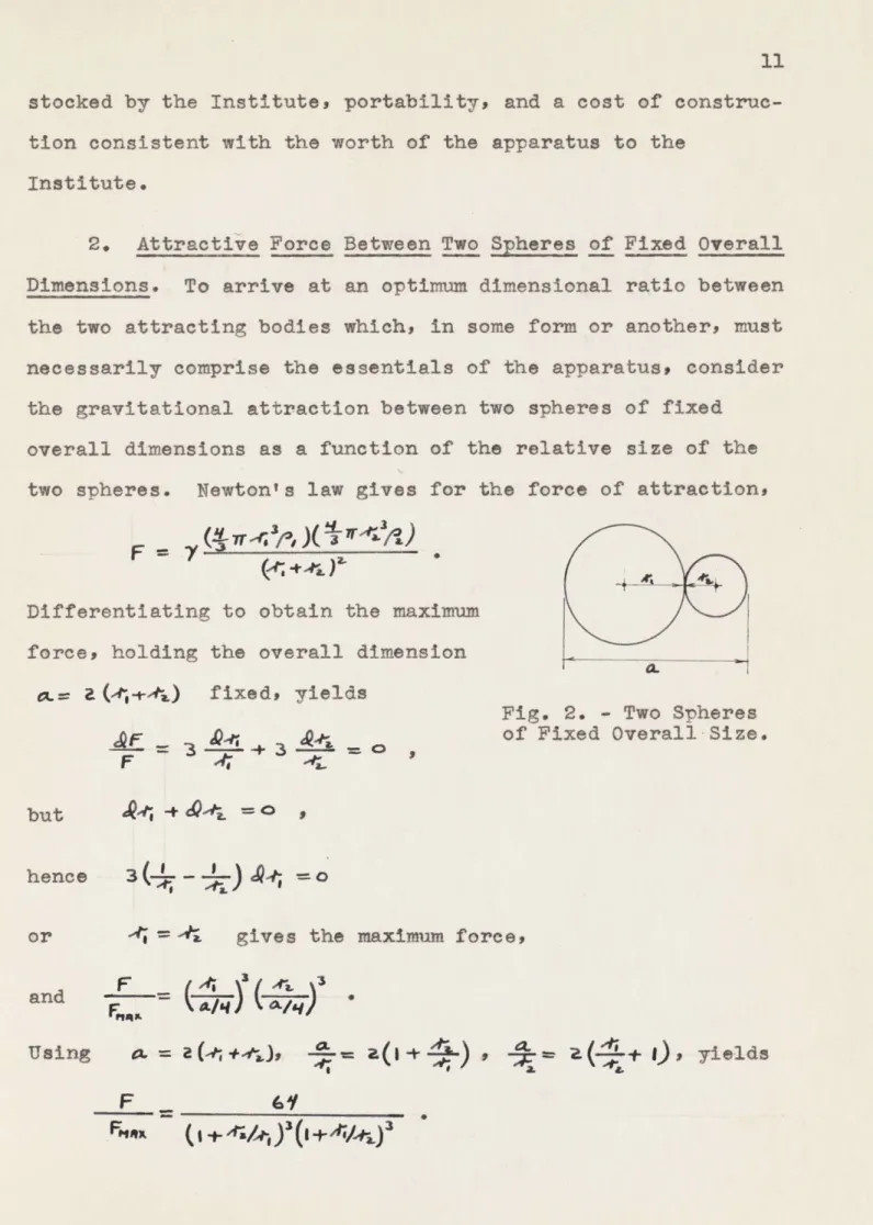
2. Attractiie Force Between Two Spheres of Fixed Overall
Dimensions. To arrive at an optimum dimensional ratio between the two attracting bodies which, in some form or another, must necessarily comprise the essentials of the apparatus, consider
the gravitational attraction between two spheres of fixed overall dimensions as a function of the relative size of the
two spheres. Newton's law gives for the force of attraction,
F
= 7rIDifferentiating to obtain the maximum force, holding the overall dimension
CaL(-,+4..) fixed, yields
Fig. 2. - Two Spheres
__ = of Fixed Overall-Size.
F -Ii
but
hence 3(- J94; 0
or -
=4.
gives the maximum force,and
Using V.
=
aU(4+ )-aF
+L, e(a +i),
yieldsF
__ _ _12 A numerical tabulation of F/Fmax as rl/r 2 F/Fma
a function of r1/r2 is given at the 1.0 1.00
0.8 0.96
right. The attractive force drops 0.6 0.82
0.4 0.54
to half the maximum for rl/r2 0.38 0.50
0.2 0.17
0.38 and approaches zero with 0.01 0.0000
extreme rapidity thereafter.
An analogous analysis of the force per unit length acting between two parallel infinite cylinders of fixed overall
diameter gives , 1(0
a closely similar function which has a maximum value of unity
at ri = r2 and a value of 1/2 at rl/r2 = 0.31 * These results
indicate the need for a departure from the conventional construction consisting of a small pendulum acted upon by relatively large masses. To obtain the maximum actuating force with an apparatus of given overall dimensions clearly requires that the attracting bodies be of comparable size, for the two cases considered, and further, the specific geometry employed appears to have no critical influence upon this
requirement.
3. Desirability of a Non-Conservative Field. The
inherent conservative nature of a stationary gravitational field, which severely restricts the amount of work available to produce a measurable effect, has been a fundamental
limita-tion upon the sensitivity attainable with convenlimita-tional
designs. This limitation may be precisely stated in the form,
(I + 4ap/r;) 1(I + -Ve4 2,
If, however, the gravitational field is
time-variant, then clearly, in general, fG(it)- ri . o ,
that is, a time-variant field is non-conservative and hence inherently capable of doing an unlimited amount of work in
producing a measurable effect. A precisely controlled,
time-variant gravitational field can be obtained, conveniently, by rotating an asymmetric mass at a uniform angular velocity.
4. The Rough Design. A prolonged consideration of a
wide variety of possibilities eventually led to the formulation
of the rough design sketched in fig. 3, on the next page. Of
all the designs considered, this is the only one that appears to be capable of meeting the design specifications for
sensitivity. The high sensitivity is achieved by the combined effects of using reacting masses of comparable size, a non-conservative gravitational field, and a compound oscillating system.
The non-conservative field is provided by two opposed, annular quadrants, of about 25 cm. in outer diameter, rotating at about 450 rpm, or some such convenient sub-multiple of
60 cps not imposing excessive stresses on the apparatus, and
driven by an appropriately wired synchronous motor. The choice
of this particular shape for the rotor rests upon three
primary considerations. First, shapes bounded by cylindrical surfaces and planes are easily machined with high precision on
standard machine-shop equipment, such as lathes and milling
14 Rotor nner Pendulum Ou er Pendulum /~ /// // / Torsion Tube, Supported at Upper and Lower Ends Image Coincidence Brass Lead Molded Plastic
Both Pendulums Tuned to Resonate at Twice the Rotational
Frequency of the Rotor.
Scale: Rotor Dia. About 25 cm.
depicted in the sketch intuitively appears to provide a greater gravitational torque than any other conceivable
geometry. Third, as will be proven rigorously in a subsequent section, and as, in fact, can be seen without too much
difficulty directly from the quadrature symmetry involved, a pair of opposed quadrants provides perhaps as close an
approach to a simple, sinusoidal variation of torque with respect to angle of rotation as can be realized, since all even harmonics are absent. It also will be shown that the odd harmonic content can be controlled by a proper choice of
relative dimensions. A secondary advantage of this
construc-tion is that the fairly large centripetal stresses can be carried safely by the same structure which provides the
gravitational field, a feature which eliminates, for example, the auxiliary stress-carrying structure which would be needed
to support a pair of rotating spheres. Brass has been
specified as the rotor material both because it is the
heaviest, commonly available material capable of maintaining its shape under moderately large stresses and because the
common varieties of brass consist principally of copper, zinc,
and lead. The first two constituents are diamagnetic
materials and the third is a paramagnetic material, so that selection of a composition quite likely can be made which will have a magnetic susceptibility substantially matching the
slight paramagnetic susceptibility of air, thereby eliminating magnetic interaction between the rotor and the pendulum
16
shielding permits bringing the reacting masses closer together, which is a material gain because of the inverse square
variation of gravitational forces with distance.
Computing the gravitational field of a pair of opposed quadrants constitutes a major design problem, which will be solved completely in sections 5, 6, 7, and 8 of this chapter.
The outer pendulum consists of two, diametrically opposed lead spheres encased in a light, plastic mold of cylindrical shape. The time limitation upon the calculation of results, contained in the design specifications, demands that one of the reacting masses be of spherical shape, for mathematical simplicity. The cylindrically symmetric supporting structure preserves this mathematical simplicity, since its effect
clearly is calculable as a small reduction in the effective
density of the spheres. The outer pendulum is supported at
the top and bottom by torsion tubes of such design that the system will resonate as a torsion pendulum at the frequency of the time-variant gravitational field, which clearly is twice
the rotational frequency of the rotor. Torsion tubes are
included at both top and bottom to enhance lateral rigidity and thereby minimize the necessary clearance between the rotor and the pendulum. The fact that the gravitational field has been arranged so as to have twice the rotational frequency minimizes mechanical coupling due to vibration.
The inner pendulum consists of a small rectangle of
optically flat glass, aluminized on one face, and supported as a torsion pendulum by two quartz (or nickel) fibers each about
10 microns in diameter and about 10 cm. in length. Quartz (or nickel) has been specified because of a high ratio of shear modulus to coefficient of shear viscosity. The inner pendulum
is mounted in a Pyrex tube evacuated to about 10-6m. Hg and
permanently sealed off. The Pyrex tube is rigidly attached to
the center of the outer pendulum. The inner pendulum is tuned to resonate in torsion at the frequency of the time-variant gravitational field.
A standard galvanometer lamp and scale, at a distance of about one meter, completes the essentials of the rough design. The lamp is adjusted so that the image of its hairline is
projected to the mirror of the inner pendulum and reflected back to the scale. Preliminary performance estimates, based upon equations of motion of the compound pendulum system to be
derived presently, indicate that the overall sensitivity of the apparatus can be made sufficiently high that steady-state
oscillations of the inner pendulum will exceed a full 3600 in
amplitude. Amplitudes in the vicinity of 900 or any integral
multiple thereof can be measured easily with good accuracy simply by image coincidence or departure from coincidence. At an amplitude of 900, for example, the mirror oscillates through an angle of 1800, and the image reflected from the back of its aluminized face comes into coincidence with the
image reflected from its front face. Two projection lamps,
placed at measured angles, can be used to provide an image coincidence at any predetermined amplitude, or any arbitrary amplitude can be measured by adjusting the angle between two
18 lamps until two images appear on the scale.
The steady-state equations of motion of the compound pendulum system prove to be quite simple, provided that the
amplitude of the outer pendulum is very small as compared with
900. One fundamental reason for the choice of a compound
pendulum for the oscillating system is that, at resonance, the amplitude of the outer pendulum drops substantially to zero,
so that the equations of motion assume this simple form. At
the same time, the amplitude of the inner pendulum becomes large and directly proportional to the gravitational driving
torque, which the apparatus is designed to measure. For ease
of reference during design calculations, it has proven conven-ient to have the complete equations of motion expressed in a
carefully tabulated order. The derivation which follows,
compressed to conform with this requirement, starts with Newton's second law and proceeds by electrical analogy.
Notation:
Subscript (,): Outer pendulum.
Subscript (x): Inner pendulum.
J : Moment of Inertia.
ri: Viscous damping torque coefficient.
n.6:
Coefficient of shear viscosity.M: Elastic torque coefficient. m.: Shear modulus of elasticity.
e
: Angle of displacement from equilibrium.or,: Amplitude of gravitational torque fundamental.
c3: Resonant frequency.
A O : Half-power band width.
Q : Figure of merit for oscillator. ( '4./cc)
R&: Outer radius of torsion element.
R,: Inner radius of torsion element.
J,
0,+ .0,-Y.(,-d).
d..-
M(&- )
n,
lAlC:-4'J+
4+ba(&.4,+MJL(4-4,)=
CRIC1
Ot
I4~
Equations of Motion(a) Range of validity: 9, << 7r/.
Approximations Refinements
(b) Qa>>I
(c) , ,
(1) 7; G
n
Y,4
,6.i+O(2)
,./a,=
Qa.
&/6,
=
i
..
gQL
(4) c,' Me/a, M,/4 ,
Torsion Tube
(5) M= w M. (F-R")/aL
(6) V
=
7r Y (R'-R,9)/a.LMost of these equations are obtainable by inspection from the
electrical analogy. The last two, which give the elastic and
viscous torque coefficients of a cylindrical tube or wire, were derived by volume integration directly from definitional
V 6i x -to el Ca, i VM3, RIL T
20
concepts.1
A second fundamental advantage of the compound pendulum
is contained in the approximation (1), which states that the amplitude of the gravitational torque driving the outer
pendulum is equal to the elastic torque coefficient of the inner pendulum multiplied by the amplitude of the inner
pendulum. (The electrical analogue of this approximation is
that, at resonance, the applied voltage El appears across the
capacitance C2*) Thus, the relatively large gravitational
torque produced by employing a massive outer pendulum of size comparable to that of the rotor is transmitted substantially without loss to the small inner pendulum, so that a large, easily measured deflection is obtained.
The procedure for formulating a design to meet a desired set of performance specifications is to work through the
approximations first, 'in the order in which they are
tabulated, particularizing the parameters, as they arise, to meet the specifications. The results are then improved by
working through the tabulated refinements. The driving torque, which appears in equation (1), must be known in order to
initiate quantitative calculations.
1 F. Sears, Principles of Physics I, Addison-Wesley,
5. Field of Opposed, Cylindrical Quadrants. Computing the gravitational field of a pair of opposed, circularly cylindrical quadrants has generally been regarded as far beyond the realm of practicality and has never before been
attempted, although such geometry clearly is an optimum. The
inherent complexity of the geometry and the practical require-ment that the solution be characterized by computational
simplicity both demand that the method of attack be planned with care. The solution is guided by two simple principles of fairly general applicability:
(1) Asymptotic Behavior. The asymptotic behavior of
the solution is first investigated by formulating the
calculable limiting solutions and the calculable solutions along any axis or surface where symmetry considerations effect
a simplification. Auxiliary boundary conditions are thus
established which free the problem from its original geometry, and sufficient insight into the nature of the solution is
gained to permit selection of a coordinate system capable of expressing the solution in simple form.
(2) Salient Function. From a study of the
asymp-totic behavior of the solution, a salient function is then formulated which establishes, in natural functional form, as
many of the salient features of the solution as possible. A
salient function which describes the discontinuities, for example, can effect a marked simplification of the problem.
Finally, the salient function is extracted from the
22 orthogonal expansion methods, with reasonable assurance that the complete solution will be expressed in as simple a form as possible and that the residual expansion will converge with good rapidity.
6. Opposed, Cylindrical Quadrants of Infinite Length. The asymptotic behavior of the solution as the length of the
sectors becomes infinite proves to be calculable. To improve the symmetry of the problem, the field of an unbroken cylinder of the same diameter and length as the sectors and of half their density is subtracted from the solution, so that the residue becomes, mathematically, the field of four quadrants
of alternating positive and negative half-density. Since the
subtracted field is cylindrically symmetrie, it cannot contribute to the torsion field and hence need not be
considered further. Clearly, the
radial planes bounding the sectors
become equipotentials. On these
equirotentials, the symmetry is
sufficient that the potential gradi-ent is obtainable by direct
integra-tion. Starting with the surface
integral form of Newton's law, and
taking full advantage of the symmetry,<
yields, referring to the figure for '
the notation,
Fig. 4. Positive-Negative Density Quadrants
Gp .= -7 R
Integration over radial plane containing P:
G
=a
-~o,w
-
g,
a_.,, * a + ft.t*-6,,0
-A
(t9-,)
y - o [(-4+e4
(4-47) - A.-;,) 4 ( 24.,..,,). =--Integration over circumferential surface:
e - .P.
/*re
)
a R 00 (ref).(
z+ V)9
/N+-n-k...4 3LL +a LtAL+Z*&.e ,LA
R 4V_ -- S( r+fB) +e%
S-A. (l.I.~a.A4.Ja-. e....% -+A]
, + A a. . .J - . e . 4 -a
k,
-- C4-(
09+A<.,r)
, .( C,+L4 It e... e.)... yr/:) -(1--*L :-*'+(%** L(er a)I
R R+ Z
&woo
,P
-Y- y,:. (:F/ )9(e....)
W*=4. .-.y7/04. a 4k 9L ;:-, 4.-q + IL IL AL + 9, 1 a w Oft a~t+0 ) *(:r-) - -Or )L C 4,0 4P,* * Ite = ',-t + a.- -rm .,.. 0 -/a..
24
Since Gp must be normal to the equipotential radial plane
containing P, the surface integral over the other radial
plane and over the end planes vanishes, and the complete integral becomes:
6,+ G,2 a
G4 =
G4,+G----
.-This result constitutes an auxiliary boundary condition which frees the problem completely from its original geometry.
Further, since any analytic function satisfies Laplace's equation, the complete solution can be obtained immediately by noting that
CL
-a
W
everywhere except at the radial faces of the sectors, where
Lis infinite. Thus the torsion field, rG*, satisifes
Laplace's equation, its value is known at its singularities, and hence it is uniquely determined simply by interpreting r,
in the boundary function for rwh as the complex variable rei0.
The real part of the result is the torsion field, as can be
the negative of the original boundary function is obtained, in
agreement with symmetry considerations. Setting 0 a *lryields
the original boundary function, and setting 191 =0 yields
zero. It follows that the solution is complete, and valid
everywhere. .
As a matter of convenience, this closed form solution
will be expanded in a Fourier series.
.--- =s I-f E ~. (~r~&) Y112 0& 4 00 mvt2. AO -t a ~~~~~ 'T(I.I+'z1(-,I 41. 44-H. a
2:
1[
1 -1.
-L
-, &%J
L JW W(A^)%+ AA Zrips('re CL)4046e to& as- Za" ee
Z 41
26 The terms involving sin 29 form a symmetric function, which will be expanded in a cosine series of corresponding symmetry.
(a(OfW)-a
TTA4 4 &aOZ
A.
ca~&0A+-=
-_____)__ e a(e-Atl)6 A4& ad--) &G c~-e~~-)G
IT
f
- (I+-)+A-:-?-IAO
o
-~ Lg~ ~ )a~-m
AAA
a
[Z 2S k{- rr ALA2 a = -- pd ge-. + A&WJ -- a
Substituting this expansion in the last equation on the previous page gives
v-G6 ( )
zI/Jfl4
a i d-r
+ _____The complete solution for the torsion field is now in
conven-ient form for subsequent use. The complete solution for the
potential field can be obtained by inspection, simply by
integrating the torsion field with respect to
e,
using anequipotential plane as one of the limits of integration, and adding in the potential field of the half-density cylinder
previously subtracted from the solution. The integration with
cos 2ne by (sin 2ne)/2n. The field of the unbroken, infinite cylinder which is to be added is obtainable by inspection from Gauss's theorem. The potential field thus becomes:
Potential Field of Opposed, Circularly
Cylindrical Quadrants of Infinite Length. a.
e
V =gravitational constant.
/ = density. Y
=potential.
> +Zv yoa (7) 4 "_AOO +
~eAA
One feature of the solution, in particular, is worth
noting. A glance at the function for the region (r4 a) shows
immediately that its Laplacian does not vanish term-by-term. In fact, from the uniqueness of a Fourier expansion, it can be seen that the solution is incapable of being expressed in the
conventional form, A Anrneane , in which the Laplacian does
vanish term-by-term, and that, had the problem been attacked by conventional techniques, a solution could not possibly have been obtained.
The solution will now be verified by showing that it satisfies Poisson's equation and the associated boundary continuity requirements,
23 Poisson's equation:
va
5.f-= o.
4
z-~
?1(0A")4$e =-A' qL) + *aa.)
aa (a+
V,
144-> a1,0) = C)
,V?-y~e, = +a ZY 4
[a,"e-N
y 29+
P-
r/
aoa
Reference to any text on Fourier analysis identifies the
summation in the brackets as a square wave of amplitude ir and
periodi 7. , /
iY~ra~e)= a ir Y/I+zw/
.., r<+<3 %. + Y/
+1, 3%e <ar
Thus, Poisson's equation is satisfied everywhere, both inside and outside the mass distribution.
Continuity of Vr and G at circumferential boundary:
Ir(W, e)
-v(o.,Ie)
jgj a VU = ZI/ MZ(M4.g) ~~ T- + 2A4I = 2 . -- +2 A06 3 2? a .+
POO =~~~AZIj+aA4 +
j A% 3Cwwo&ie)
av(a;e).
Thus, i and G are continuous at the circumferential boundary. The fact that VV has been shown to be finite in both the
region (r > a) and (r < a) rigorously completes the proof that
V and 9 are everywhere continuous, since a discontinuity in
either V or G would necessarily give rise to an infinite VaIT.
Finally, it can be seen by inspection that the field at
infinity is that of an unbroken cylinder of density /a. , the
mean density of the quadrants and the gaps between them, and that both series and their first and second term-by-term derivatives are uniformly convergent.
30
7. Opposed, Cylindrical Quadrants of Semi-Infinite
Length. With the potential field for quadrants of infinite
length now known, a three-dimensional boundary condition for the potential field of quadrants of semi-infinite length can be established simply from the requirement that the fields of
two semi-infinite quadrants, joined end-to-end, must combine
to give the field for infinite quadrants. In terms of the
coordinate system indicated in the figure, this condition
becomes I
14(re, e) +- r-go, W=VCa1, )
where I. represents the known potential
function for infinite geometry. In
particular, setting )= V yields
P 0
irk
fV(~ e)
ce k I aThese two boundary conditions more than
suffice to free the semi-infinite Fig. 5. Semi-Infinite
Quadrants. problem from its geometry. The upper
half-space bounded by the end plane constitutes a simple region, free of matter, with its boundary potential function completely specified. Further, the potential at any point below the end plane is expressed in terms of the potential above the end plane, so that only the simpler of the two
regions need be considered.
To improve the syzmmtry, the field of a semi-infinite, unbroken cylinder of half-density is subtracted from the
mathemati-eally, the field of alternating positive and negative
half-density quadrants. The boundary function in the end plane,
expressed in detail, clearly becomes
Y~r~a,%()e= .t) 4i
L LmTOW M71
A0.A MYL
half the potential field for infinite quadrants. A
square-wave function has been both added and subtracted at the end, in order to separate the second equation into two parts, such that one part, consisting of the last summation, satisfies Poisson's equation, and the other part, consisting of all but the last summati6n, satisfies Laplace's equation, in the
cylindrical coordinates (r, e) previously used.
Recalling that, in spherical coordinates (r, O, 0), solutions of Laplace's equation occur in the form
at once establishes, by inspection, a tentative formulation of the complete solution for the upper half-space region, in the form of a salient function which satisfies both the
boundary function and Laplace's equation, plus an orthogonal set of solutions of Laplacets equation which vanish on the boundary and which are available for the establishment of continuity across the hemisphere separating the two regions
32 r
>
a and r < a.%
A,%)) = e) -a -am %z) Ia (C- c)4
1
m~I~
s.ic ONO AM *h VILVAITh. seldom-used Legendre functions PCe(x) introduced
her. merit a brief discussion. These functions are particular
solutions of Legendre's equation,
{--)
l+F
l(M
Apf(xt)o )-~^4= ,specified by the associated conditions,
ark, PMa)o
A
,and normalized to conform with the normalization of the usual
Legendre functions Pm2(x), so that
The advantage of introducing these functions is that their use permits matching the boundary function term-by-term with a
solution of Laplace's equation without increasing the
multi-plicity of
ihe
summation. A few useful properties of thefunctions are tabulated below for subsequent reference.1 Of
particular importance for computational work is the fact that they are expressible as a closed summation of algebraic
functions.
P;v )
(-)h)'iI
...C )(.-+).(-M+ -).,4XM A.).--(Ma+A-u)(--x
1
? ",Me)-+ . Q(-c..ee) = 2 *) _&"x) -+-tG) 9 l454 Y;'I- = U(M)"t--f-(1+-( -x+ * (;4o) .-at^,
(0)= (1
["'M t!
To complete the solution for the upper half-space region now requires only the establishment of continuity of the
potential and the potential gradient across the hemisphere
Magnus and Oberhettinger, Formeln und Satze fur die
Speziellen Funktionen der Mathematisehen Physi ,
34
r a a. The procedure here consists simply of evaluating the
coefficients A and B. by a direct application of this
continuity requirement,
For n
=
1, these continuity equations become- P (...j/'tl(o)+(.&-+-a Af -(u)R-e I rM(r.C4)
a.
Orthogonal integration thus yields
f[A
e,'-
3/r;/(C)-+
(1+A--x-1)).-,-]
g(x)4Q-Tb. last integral involved here is well known. The others were evaluated by appropriate adaptations of the
Sturm-Liouville technique.1 The integrals are:
f~
3
(x)f
P(xj x
-f o)z 0
f F-z tof-)
I(x)Dx = (o)1 F. Hildebrand, Advanced Calculus, Edwards Bro., Ann Arbor (1948), C . 5.
Substituting these values in the
solving for An and B can be s
continuity equations
*on to yield:
+ + A^.,{S ( A*--I)(a) a )) AA -a) 4"a M-a)(,w+3)
+ - -; *V ~ )( -+ + iaa)(4.wM++-3 + a
I
+u)(4q+)(Am-a)J
= f + -t Z + v-+,a 4*3+ 7 +A.% + + 9 A% 4'+I(AA+ )(A% Z S+ + +2.(I) -- e +P"(6) -- *1 4 q - (O-XI( +3m . A (A*%+1) (AK+3)L--f-w 1 (W-S( 1)( )(M (A*% +3) 'I + (- ---3~ - i + ~,Q4
'f ~g,{14
?,W4 1 4 4-+ (6-a) + L: "(4 +I( 3)(fol-Z)J
.. + P4A44) L )+ A*% +.us-L (Z +!g( +g-Am &-" + and (Aft-a)! -B ""I q13A IU, (AOK-;t) 1 a1(36
Similarly, for n - 3, the continuity equations become:
G!71D (t...cq) mlsAzbcp + + Py (~.CA)
+4) . i C a(o) -(Vti -) q).(..4(c
Orthogonal integration yields:
+ (R-- -8)%(x) Qc 0
(a -x') (g-X ) a
P-W
+ .(- (,A) M(M- )
- (0%- 0a
Th. Integrals involved here were evaluated by appropriate adaptations of the Sturm-Liouville technique, as before, and
are: A I ?A'() pT L(o)
(AA4-2)(A44+3) 0 A f a *(L PA^ ( ALZ-M). _(a) Pa. C' -X. {A+1 A% 044
Substituting these values in the continuity equations and solving for A., and ByAn can be seen to yield:
(_-___+_ _ - - -' I (am-24itI) (-.i-)(A-+3) 1
AOK+
' o
A
(OO
I
A.
I
Af
S~A M(AO-.)(Ab4+aA+9) +J
PWI., ()
[
I(M +AA--A)-
eZ'(
0
)
L(-bt-a(4.+3)+(,b+aJ*-IA9= -4.6'--+ 3+24 4 +I-+.-.2Af (,2-9)(fIa-&-9(+Awt)
- .. f'(o) /A
(,1+ -( 3
+v44-+ Z*
( -t3 ) (0))
13A-1+a.
;7
) Af. t-.o--(u4-ZA1f(A*%PA (X) x
Z (a) !1
8
(z') ~ M(Af10 )\A% 54.,+I'(~ (- am (a)
w-[(-
-(-zH~s
i)(in-s -f*~f C46 ZIA MA+ s)4w.*- Z)~ +1++ - (*,-a- O )(*--a ( *9 )---af! (o(o (M+ 201%) ! (4- -L) a 'M(*-92This evaluation of An and B, finishes the solution for the
upper space region. The solution for the lower half-space region follows at once from the three-dimensional
bound-ary condition established earlier. Consolidating these
38
Potential Field of Opposed, Circularly Cylindrical Quadrants of Semi-Infinite
Length and of Alternating Positive and p
Negative Half-Density. V a potential. 7
=
gravitational constant. */A=
density. ~ t;cia E M-i AOAU0 j + 3 A+(a 0 ~ ()- +a)(wI)(*% ( +3) = ____ _4/a.___ (AF L a -e - -o ) a. * co C. Ir/, -AF If [...- - -AE6 - fo% -sig~CQ Aw~.,% 2'-" .e a A 4 3 %9&3 WM~ 4% OJOVW,
r-ce, 6)= Y.(,i-.4;Cp, 8) - V(,e ce, 0)y,~a ~
2
2
C@t(0A44'C9 dL] = _ _AA
. P b'**-)
At first sight, the solution appears rather formidable,
but closer examination indicates that it is in convenient form for numerical computation. The single summation, comprising the salient function, is the dominant portion of the solution,
and converges with good rapidity, as 1/n3 or better, with n
increasing by increments of 2. The double summation,
comprising the residual funiction, vanishes near the end plane, near the axis, and everywhere else except in the near vicinity
of the spherical surface r
=
a, and converges with extremerapidity, as 1/m5 or better, with m increasing by increments
of 2.
By way of comparison, an alternative solution can be formulated in terms of Laplace-Bessel transforms, using cylindrical coordinates (rez), which initially takes the
form go 0 X.
f0.0
.A4At
and which, after performance of the indicated integration, becomes
where (L) C(C-+u(c .-- (1)+(a-t), + Po
This alternative solution is in more compact form, symbol-ically, but the triple summation clearly makes it a poor second best insofar as numerical cemputation is concerned.
40
8. Opposed, Annular Quadrants of Finite Length. With
the torsion field for semi-infinite quadrants now known, the torsion field for any finite geometry characterized by cylin-drical quadrant boundaries can be formulated with ease, simply
by appropriate superposition. Further, by a judicious choice
of symmetry and relative dimensions, the superposition can be
made without increasing the complexity of the solution. The
annular geometry sketched below clearly can be reproduced
mathematically by superposition of four semi-infinite, opposed quadrants of appropriate axial positions, radii, and algebraic signs. The mathematics of the superposition is sufficiently
simple that it can be performed by inspection. If the relative
dimensions are selected so that the region of interest lies within the spherical surfaces centered on the inner rims, the
torsion field at a point P in the central plane normal to the
axis becomes:
Torsion Field of Opposed, Annular Quadrants. V
=
potential.=
grav. const.=
density. ____ A-,q %( . (* 'Q M'IO LO) AThis final solution has two features of particular
interest. First, the negative-superscript Legendre functions cancelled out completely during the superposition, so that the end result used for computation is expressed entirely in terms
of the fully tabulated functions, Pn(x) and flPR(x)dx.I,2
M0
Second, while the solution has been particularized, for simplicity, so that it is rigorously complete only in the
central plane normal to the axis, it is a rather happy circum-stance that it still formally satisfies Laplace's equation. It follows at once that apparatus misalignments involving small departures from the central plane will have no first or second order effect.
1 U.S. Bureau of Standards, Tables of Associated Legendre
Functions, Columbia University Press, New~York (1945).
' G. Prevost, Tables et Formules de Fonctions Spherique
42
9. Circular Cylinder of Finite Length. To provide
flexibility in the choice of geometry, a rapidly converging series for the potential field of a circular cylinder of finite length also will be derived. The relative simplicity of this problem lends itself to a concise illustration of the effectiveness and generality of the technique, developed in the previous problem, for expressing the solution for a finite cylindrical geometry in terms of the more readily calculable analogue for infinite cylindrical geometry. For a cylinder of
densitya., of radius 4., and of infinite length, the potential
field is obtainable by inspection from Gauss's theorem, and is
(*wa)= wvy/ lI+ e, , V-4.) = Vr_ seg,
where r is the distance from the axis and y is the
gravita-tional constant. 1equiring that the fields of two
semi-infinite cylinders, joined end-to-end, combine to give the
field for an infinite cylinder, establishes a three-dimensional boundary condition for the semi-infinite case, which, in terms,
now, of the spherical coordinates indicated
in the figure, clearly becomes
In particular, setting . yields
-Fig.6 . Semi-Infinite
+-,
(4) Cylinder.The upper half-space bounded by the end plane constitutes a matter-free region with its boundary potential function
completely specified. Further, the potential at any point below the end plane is expressed in terms of the potential
above the end plane, so that only the simpler of the two
regions need be considered.
Recalling that solutions of Laplace's equation occur in the forms,
at once establishes a formulation of the complete solution for the upper half-space region, in the form of a salient function which satisfies both the boundary function and Laplace's
equation, plus an orthogonal set of solutions of Laplace's equation which vanish on the boundary and which are available for the establishment of continuity across the hemisphere
separating the two regions r> a and r < a.
U. L (0
Evaluating A. and Bn from the continuity requirement,
V(4, q) - Y(.~,cO) = 0 = VV W) e)-VVU, ) ,
44
f
[t-A
]
Xi.
+W
(1.
>
-)|
'3111()&A
.
(0
Integrals arising at this stage of the solution, in general, are readily evaluated by appropriate adaptations of the Sturm-Liouville technique, since the integrands involve only the product of two solutions of the same differential equation or
its degeneracies. The integrals here are:
(x P(.X) &x *A
u.~~ (MAxO%
(x'.W PAx = a
0W
*C)PInserting these values in the continuity equations gives:
=_--2-o) - + P'(o)
P240) 1 [ *+.Z
4A(& P-A%3] = __ o____)___A ___
* )a(o+3)
+3 P2(o) P, P+ .
0(,)
p
J (O) +e) i -A4 m).+^i
a P(o)
takes the relatively simple form:
Potential Field of Circular Cylinder of Semi-Infinite Length. -V
=
potential. y=
gravitational constant.=
density. ____n___cton ,(+ rj Pan(b) obaineby bein
0itac frmteedo tecne ge1- W%-tomprdwt
+% +
_______- ~ ~ ~ ~ P. (0~c) -)
its radius,1&Lc)
Zn
beitrrte&(nc
Pi4 (4&y
stefil)hc A4= IA..1A
V4-r-C) i (xi q).-rc)
It is interesting to note that a physical interpretation of the
salient function, ria (boLnq) d , can be obtained by observing
that this term is the dominant portion of the solution at a distance from the end of the cylinder large as compared with its radius, and hence it may be interpreted as the field which
would result if the entire mass of the cylinder were concen-trated on its axis.
Proceeding to any finite geometry characterized by
circularly cylindrical boundaries involves only simple super-position of semi-infinite solutions* For a cylinder of finite lengths for examples the potential field outside the cylinder
46 the dual coordinate system arising from the superposition, can be seen to become:
Using the relations, ,
A= (ec
Aft
I+"1'f
Abrings the symetry of the solution clearly into evidence, in the form:
Potential Field of Circular Cylinder. potential.
-Y = gravitational constant. /0
=
density.P is any point outside cylinder
and outside hemispheres centered
on its ends.
+- 0 +
(
) P .( o o C .)6 41Constants arising from the superposition, which can be shown
to sum up to asy/@[ +aL- a 4 -A.
-..
g9
, where h is half theheight of the cylinder, have been dropped, for simplicity, a
deletion which shifts the zero potential reference from the geometric center of the cylinder out to infinity. The
associated solutions for the regions inside the hemispheres and inside the cylinder can be formulated with equal ease.
To investigate the amount of labor involved in obtaining numerical results, the gravitational acceleration at a point on the lateral surface of a cylinder midway between its ends will be computed, for a cylinder whose height is equal to its
diameter. Taking r;= q= a , , yields:
G 0[4& CPO- +
,.'A
ce ? (-..0. Ay/e ..Thshafa pa siof num___a calcula IS/ ufIce *to: gsil
are, r (A -ti)ey
Gw 3h -Z I./ Ia Co ,7% Vo nifni lne.56 T+uti b
w;:
tJ+ L!mt' aa +9,) a .s Th3 S 7 & 7.35 ;-S-7./I-i3~*
asIB1
al'
a
M
a
zza
+ [ o. 07375 -O0. 40Oqag 0.OO 3 7 q + o*aq I +.0 0 03 7-se 1.09VI53
Thus, haif a page of numerical calculations suffices to give
four-figure accuracy. A feel for the order of magnitude of
the result can be had most quickly by comparing it with the fields at the surface of a sphere of the same radius and at
the surface of an infinite cylinder of the same radius, which
are, respectively,
wla
j o
pee
67 =~ WY10- ,for an infinite-cylinder.
The result lies between these limits, as it should. The effect of the inverse square law is clearly evidenced by the fact that the field is only 25% less than it would be if the cylinder were extended to infinity.
48 It can be shown that the series has a singularity in the complex z-plane which gives rise to slow convergence in the vicinity of the points where the axis of the cylinder pierces
the hemispherical surfaces centered on its ends. Elsewhere,
the rate of convergence is about as indicated by the above numerical example, or better. The salient function alone, or
Y/
4pi
Q.
(to.~e4&
7r Y, %''
provides sufficient accuracy for most design calculations, an approximation, it will be recalled, which is equivalent to regarding the mass of the cylinder as concentrated on its axi s.
CHAPTER 4
SUGGESTIONS FOR FUTURE WORK
An independent derivation of the torsion field of opposed, cylindrical quadrants is in the process of being formulated, by the use of the Fourier-Bessel transform mentioned briefly
on page 39. The first term of the summation on page 38 has
been obtained directly from this transform, and further manipulation of the transform appears to be leading to a complete solution expressed entirely in terms of
negative-superscript Legendre functions. Completion of this
indepen-dent derivation is felt to be advisable for two reasons: first, to eliminate the possibility of an error, and second, to see if the alternative derivation suggests a simpler
formulation of the results.
Completion of the design logically requires, next, a determination of the relative dimensions of the rotor which will provide maximum gravitational torque, minimum harmonic
content, and rapid series convergence. The design then can be
particularized to specific dimensions and placed on a quanti-tative basis.
The progress made thus far represents 19 weeks work,
averaging about 25 hours a week. Completion of the project,
it is estimated, will require an additional 950 man-hours, divided about equally between design, construction, and

![Risiko- & [und] Schutzfaktoren der psychischen Gesundheit humanitärer Einsatzhelfer : eine systematische Literaturübersicht](data:image/gif;base64,R0lGODlhAQABAIAAAP///wAAACH5BAEAAAAALAAAAAABAAEAAAICRAEAOw==)