HAL Id: in2p3-00169268
http://hal.in2p3.fr/in2p3-00169268
Submitted on 3 Sep 2007HAL is a multi-disciplinary open access
archive for the deposit and dissemination of sci-entific research documents, whether they are pub-lished or not. The documents may come from teaching and research institutions in France or abroad, or from public or private research centers.
L’archive ouverte pluridisciplinaire HAL, est destinée au dépôt et à la diffusion de documents scientifiques de niveau recherche, publiés ou non, émanant des établissements d’enseignement et de recherche français ou étrangers, des laboratoires publics ou privés.
A single bunch selector for the next low β continuous
wave ion beam
G. Le Dem, M. Di Giacomo
To cite this version:
G. Le Dem, M. Di Giacomo. A single bunch selector for the next low β continuous wave ion beam. 22nd Particle Accelerator Conference (PAC’07), Jun 2007, Albuquerque, United States. Joint Accelerator Conferences Website; IEEE, pp.158-160, 2007, �10.1109/PAC.2007.4440144�. �in2p3-00169268�
A SINGLE BUNCH SELECTOR
FOR THE NEXT LOW β CONTINUOUS WAVE HEAVY ION BEAM *
G. Le Dem
#, M. Di Giacomo, GANIL, Caen, France
Abstract
The MEBT line of EURISOL heavy ion post-accelerator and the SPIRAL2 deuton/ion post-accelerator should transport a continuous wave (cw) beam from a 88.05 MHz RFQ (β respectively 0.035 and 0.04) to a drift-tube linac. A high frequency chopper is being studied to select only 1 bunch over N, respectively 10 < N and 100 < N as asked by the physicists. It requires pulse voltages up to 2.5k kV, rising in less than 6 ns at a repetition rate up to 8.8 MHz. These figures are at the border of what can be provided by the travelling wave fast choppers and the capacitive-type chopping technologies [1,2,3,4]. We have reviewed the current fast and slow chopping structures and their associated pulse generator [5]. Some preliminary RF simulations to adapt the present chopping devices to our requirements are presented. The main limitations of these technologies when applied to select one bunch in cw ion accelerators are also shown. Our first studies and results to solve the arising problems are discussed.
INTRODUCTION
The MEBT line of the EURISOL post-accelerator and the SPIRAL2 accelerator should transport continuous wave (cw) beams from a RFQ operating at the 88.05 MHz frequency (Δt = 11.36 ns) to a drift tube linac (DTL). Both superconducting linacs are designed to have effective acceleration respectively for radioactive heavy-ions with a ratio A/q from 4 to 8, and either for deuton or heavy ions with a A/q of 3 and 6. The maximum beam current is respectively 1 μA and 5 mA. The space charge effects are negligible in the EURISOL case. Many EURISOL experiments will require to chop the beam for periods from 10 ns to 1 ms, which will be made by means of a high frequency chopper located in the MEBT line. Due to the physicist requirements the EURISOL and SPIRAL2 choppers should operate like a single bunch selector: one bunch over N should pass through the chopper output with the repetition rate resumed in table 1.
After having adapted existing 50-Ω travelling-wave (TW) electrodes to our cases, power constraints will be observed due to the cw mode of the beam and the physicist requirements. Two alternative ways might answer the requirements. We also decided to investigate another way to decrease power consumption: a 100-Ω meander microstrip line. The length of the strip line can lead to attenuation and dispersion of the pulse signal along its propagation.
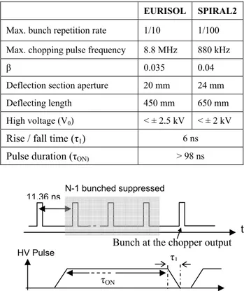
Table 1 : MEBT Chopper Specifications.
EURISOL SPIRAL2 Max. bunch repetition rate 1/10 1/100 Max. chopping pulse frequency 8.8 MHz 880 kHz
β 0.035 0.04
Deflection section aperture 20 mm 24 mm
Deflecting length 450 mm 650 mm
High voltage (V0) < ± 2.5 kV < ± 2 kV
Rise / fall time (τ1) 6 ns
Pulse duration (τON) > 98 ns
Figure 1: Beam structure and Chopping time structure.
CW MODE CONSTRAINTS
Fast rising times can be achieved either by travelling wave structures [2,3,4] or by capacitive-type (C-type) chopper [6]. This scheme is used when rise time lower than 10 ns are searched. Chopper structure working at voltage level similar to those required for EURISOL are being studied for proton injectors foreseen to operate in the 300 to 400 MHz frequency range and within rise/fall time of the deflecting pulse shorter than 2 ns. In preliminary studies the 50-Ω SPL electrode was adapted to EURISOL and SPIRAL2 cases. For EURISOL and SPIRAL2, N-1 bunches over N should be suppressed where N exceeds respectively 10 and 100. These values imply a duty cycle of the high voltage pulses always higher than 80 %. If a 50-Ω SPL type electrode is used, the pulse generator has then to provide a average of RF power > 112 kW, which is lost at 50-Ω RF matching load and at the equivalent resistance of the conductor strip. The power losses also exceed 6 kW. Previous studies made by F. Caspers and T. Kroyer show that around 100 W of heat power can be dissipated for an operation temperature 100 K above the cooling temperature [1].
N-1 bunched suppressed
Bunch at the chopper output 11.36 ns
t
τON
HV Pulse τ
1
MOPAN008 Proceedings of PAC07, Albuquerque, New Mexico, USA
07 Accelerator Technology Main Systems 158
T28 Subsystems, Technology and Components, Other 1-4244-0917-9/07/$25.00 c 2007 IEEE
ALTERNATIVE SOLUTIONS
To decrease RF power and power losses, two alternative solutions seem to be good candidates: either a C-type structure like the RAL-ESS slow chopper [6] or an association of a TW electrode and a static B-filed steerer.
Capacitive-type Chopper
Figure 2: Scheme of a C-type chopper.
C-type choppers are typically based on capacitive electrode driven by a fast high voltage switch. To increase the repetition frequency and the transition times the electrode can be divided into several smaller capacitive elements. A similar C-type chopper has already been studied like the RAL-ESS “slow chopper” project [6], which consists of a vacuum box with discrete electrodes, each attached to a vacuum feed-through (ceramic insulators) and driven by own “slow pulse generator” (SPG). In these devices the handled power depends on the total effective capacitance (chopper, connections, switch …). Assuming a total capacitance of 100 pF, a 2.5 kV high voltage and the notations of Figure 1 and in Table 1, the power consumption is estimated up to 11.2 kW in our case. The RAL SPG can provide a 6 kV high voltage, 15-ns transition time pulse with duration from 100 ns to 100 μs, within pulse repetition frequency limited at 1.3 MHz. Although RAL SPG seems to be optimistic for our cases, some power studies have to be done to estimate the feasibility and to reach our requirements.
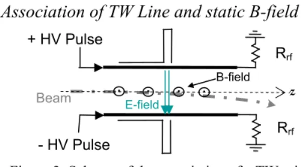
Association of TW Line and static B-field
Figure 3: Scheme of the association of a TW mircrotrip line and a static B-field steerer.
Figure 4: high voltage pulse with inverted duty cycle.
We propose to invert the duty cycle by means of a static B-field steerer (see Fig. 3): bunches are always deflected. The electromagnetic (EM) pulse, provided by two opposite electrodes fed by high voltages of different sign, should cancel the previous deflection effect: thus the EM pulse should let pass one single bunch through the chopper. The pulse duration falls to 7 ns instead of 96 ns (see Fig. 4).
Table 2: New specifications of the HV pulse and estimated power performances.
Preliminary studies have been devoted to adapt the SPL structure for EURISOL and SPIRAL2 cases. Due to the different particle velocities, calculi and 3D EM simulations give an electrode broader in the first case (see Tab. 2). We expect RF powers and power loss respectively up to 11.45 kW and 622 W at a 10 % DC. In the SPIRAL2 case, the SPL electrode type seems compatible with the insertion inside a steerer and with the 100 W limit of heat power which can be dissipated by a ceramic plate. However we exceed this limit in the EURISOL case.
100-Ω MICROSTRIP LINE WITH
INVERTED DUTY CYCLE
Design & Studies
Figure 5: Design of the 100-Ω meander line. To reduce power consumption and power losses, we decided to investigate a new travelling wave chopper, shown in Figure 5, based on a 100-Ω meander line. The conductor strip is deposited on a ceramic plate (εr = 9.6).
After having studied a few values of the gap, a 3-mm gap seems to be a good compromise satisfying the insertion inside a steerer and the beam dynamic requirements. The electrode width is 45 mm and the coverage factor 74 %. By means of 3D EM simulations with Microwave Studio®
EURISOL SPIRAL2
Electrode width 73 mm 64 mm
Duty Cycle < 10 % < 1 %
High voltage (V0) < ± 2.5 kV < ± 2 kV
Rise / fall time (τ1) 6 ns
Pulse duration (τON) 7 ns
RF power < 11.45 kW < 1.14 kW Power losses (RJ = 2.35 Ω) < 622 W < 62 W HV Pulse τON Beam before chopper τ1 N-1 bunched suppressed 12 ns E-field Beam C-types electrodes la = 45 mm gap = 3 mm 20 mm 0.45 mm (Zc = 100 Ω) y x z 0 + HV Pulse Beam - HV Pulse E-field Rrf B-field
. .
.
.
z RrfProceedings of PAC07, Albuquerque, New Mexico, USA MOPAN008
07 Accelerator Technology Main Systems 1-4244-0917-9/07/$25.00 c 2007 IEEE
T28 Subsystems, Technology and Components, Other 159
of CST, the variations in the coverage factor as a function of transverse position are shown in figure 6 for three different values of the gap. One observes a 27 mm width of the field uniformity where the vertical deflecting E-field is always higher than 97 % of its maximum value.
Figure 6: Transverse coverage factor on the beam path.
Comparisons
Assuming a 2.5 kV high voltage and a 10 % DC, the RF power falls to 5.63 kW in the 100-Ω meander line instead of 11.45 kW in the 50-Ω SPL line. The conductor resistances are estimated respectively around of 7.35 Ω and 2.87 Ω, which imply respectively power losses lower than 386 W and 622 W. If we limit the power loss to the value (100 W) which can be dissipated by a ceramic plate, we gain 30 % on the high voltage (1.26 kV instead 0.94 kV) and on the RF power (1.46 kW instead 1.74 kW). Furthermore the 100-Ω electrode width of 45 mm is more interesting for the insertion inside a steerer than the 73 mm SPL line adapted to EURISOL. The 27 mm width of the E-field uniformity, described on the figure 6, is better than the 20 mm width, obtained by a SPL double meander line adapted to EURISOL.
Pulse propagation
Since the ideal pulse plotted in Figure 4 is a periodic function, one can decompose it into a Fourier series. For any duty cycle the theoretical high harmonic is 440 MHz if a voltage gap < 40 V (< 2 %) is accepted. A microstrip line has a group velocity and an attenuation which depend on the frequency and which lead to pulse shape distortion for long structures. 3D EM simulations of a short 100-Ω meander line at the frequency range up to 440 MHz show a good transmission and a good matching. Then the phase of S21 depends on the velocity to the minus one.
Thereafter the delay time of each harmonic may be deduced from the velocity and be implemented in the Fourier series. The attenuation due to the conductor loss has to be taken into account too for the harmonic magnitude calculation. In figure 7 are plotted the input and output pulses versus time in a 7.297 m microstrip line, equivalent to a 450 mm long electrode. The maximum variation is close to 300 V (< 12 %). Due to this variation and the fringe field effects, the static B-field could not be perfectly cancelled by the EM pulse. Consequently partially beam would be deflected instead of passing through the chopper.
Figure 7: Comparisons between input (dot) and output (solid) pulse of a 7.297 m long microstrip line.
CONCLUSION
Association of a static B-field steerer with a TW chopper is essential to invert DC. A SPL 50-Ω electrode seems to be adapted for SPIRAL2. To reach 10 % DC, a 100-Ω line electrode is the first step but there remains still much work to reach 2.5 kV. From a review of existing generators [5], requirements for the chopper are at the border of the existing structures: one can expect a maximum 2 kV high voltage within 7 ns rise-time and a 1 % DC (from [3,4]). At this day we wait for answers of commercial factories about feasibilities for pulse generators. Furthermore studies must be done to decrease the frequency bandwidth of the generator by modifying the pulse shape. Electrodes prototypes of the EURISOL and SPIRAL2 choppers are foreseen to be developed in a near future.
ACKNOWLEDGEMENTS
We acknowledge F. Caspers, T. Kroyer, A. Lombardi and M. Paoluzzi at CERN, as well as M. Clarke-Gayther at RAL for their help and their information.
REFERENCES
[1] T. Kroyer, F. Caspers and E. Mahner, “The CERN SPL Chopper Structure, A Status Report”, CARE-Report-06-033-HIPPI, CERN, Januar 10th, 2007.
[2] F. Caspers, Y. Cuvet, J. Genest, M. Haase, M. Paoluzzi and A. Teixeira, “The CERN-SPL Chopper Concept and Final Layout”, EPAC’04, Lucerne, July 2004, p. 1141. [3] M. Clarke-Gayther, “Fast-Slow Beam Chopping for
Next Generation High Power Proton Drivers”, PAC’05, Knoxville, May 2005, p. 3635.
[4] R. Hardekopf, S. Kurennoy, J. Power, R. Roybal, D. Scharge, R. Sherwood and S. Collins, “Fabrication of the MEBT Chopper System for the Spallation Neutron Source”, PAC’03, Portland, May 2003, p. 1661. [5] G. Le Dem, “High Frequency Chopper of the
Heavy-Ion Accelerator – Annual Status Report”, April, 2007, http://www.eurisol.org/site01/doc_details.php? EURpub=1&dID=757&tID=10.
[6] M. Clarke-Gayther, “Beam Chopper R&D for Next Generation High Proton Drivers”, HIPPI’06 general meeting, Geneva, May 2006.
∆max = 300 V (12 %)
Voltage [V]
t (ns)
MOPAN008 Proceedings of PAC07, Albuquerque, New Mexico, USA
07 Accelerator Technology Main Systems 160
T28 Subsystems, Technology and Components, Other 1-4244-0917-9/07/$25.00 c 2007 IEEE